1
PRO ® U120
User Manual
A91M.12-271956.06-0894
PRO ® U120
Type: PRO-U120
Version 5.1
Configuration Instructions
DOK-276566.06-0894
Part of Software Package E-No. 424-275117
Overview
Notes
Table of Contents
Part I
How to proceed
Part II
Main Menu PRO ® FWT
Part III
Configuration Instructions
Part IV
KOS 201 - Parameter assignement
Part V
File Structures
Part VI
Index
Part VII
Appendix
Part VIII
Part IX
05
05
Notes
Table of Contents
05
v
vi
05
Notes
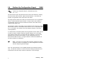
Application Note
Caution The relevant regulations must be observed for control
applications involving safety requirements.
For reasons of safety and to ensure compliance with
documented system data, repairs to components should be
performed only by the manufacturer.
Training
AEG offers suitable training that provides further information concerning the
system (see addresses).
Data, Illustrations, Alterations
Data and illustration are not binding. We reserve the right to alter our products in
line with our policy of continuous product development. If you have any
suggestions for improvements or amendments or have found errors in this
publication, please notify us by using the form on the last page of this
publication.
Addresses
The addresses of our Regional Sales Offices, Training Centers, Service and
Engineering Sales Offices in Europe are given at the end of this publication.
05
vii
Copyright
All rights reserved. No part of this document may be reproduced or transmitted
in any form or by any means, electronic or mechanical, including copying,
processing or any information storage, without permission in writing by the AEG
Aktiengesellschaft. You are not authorized to translate this document into any
other language.
Trademarks
All terms used in this user manual to denote AEG products are trademarks of
the AEG Aktiengesellschaft.
ã 1994 AEG Aktiengesellschaft.
viii
05
Terminology
Note
This symbol emphasizes very important facts.
Caution This symbol refers to frequently appearing error
sources.
Warning This symbol points to sources of danger that may
cause financial and health damages or may have other
aggravating consequences.
Expert This symbol is used when a more detailed information is
given, which is intended exclusively for experts (special training
required). Skipping this information does not interfere with
understanding the publication and does not restrict standard
application of the product.
Path
This symbol identifies the use of paths in software menus.
Figures are given in the spelling corresponding to international practice and
approved by SI (Système International d‘ Unités).
I.e. a space between the thousands and the usage of a decimal point
(e.g.: 12 345.67).
05
ix
Abbreviation
Explanation
ALU
A-byte
A1-byte
AWD
IL
BGT
D1-, D2-, D3-, D4-byte
DM
I/O module
EZM
F-byte
GRW
KOS
MW
NLQ
PV-Number
UST
ALU 200/201
Address byte in SEAB-1F
Subaddress byte in SEAB-1F
Automatic selection
Instruction list
Subrack
1st - 4th data byte in SEAB-1F
Double-point information
Input/output module
Real-time information
Function byte in SEAB-1F
Limit value
KOS 201/210
Measurand
Near Letter Quality
Process variable number
Outstation
x
05
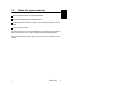
Objectives
This description is intended for configurers of Geadat U120 outstations.
The configurer is then able to
install the programming device,
install the software,
configure with the software,
document the configuration,
pass the parameters obtained,
transfer the generated IL to the controller and start it.
Arrangement of This Guide
05
Part I
Check list how to proceed in order to start operations with
an outstation.
Part II
Description of the main menu PRO-FWT.
Part III
This part describes how to configure the Geadat U120
outstation with PRO ® U120.
Part IV
This part describes how to parameter the KOS 201/210
directly or with PRO ® U120.
Part V
File Structures
Part VI
contains the index.
Part VII
contains the user comments and the list of addresses.
xi
Relevant documentation
Geadat U120 User Manual
Dolog AKF ® A120 User Manual
Validity
This description is valid for the:
Software
PRO ® U120, Version 5.0
Dolog AKF ® A120, Version 5.0
Basic software versions
ALU 200
276 689.00
ALU 201
276 690.00
Firmware package: KOS xxx FPM 001
containing
FWM 001
FWM 002
FWM 007
FWM 008
xii
277
275
275
261
261
782.01
125.06
126.01
541.00
142.00
(SEAB)
(APS)
(SEAB 8k RP)
(AWD 8k RP)
05
Handling 3 1/2” Diskettes
No cleaning of diskettes.
Store diskettes in protective
containers and boxes.
Temperature 10 to 60 C
Humidity
8 to 80%
No water on diskettes.
Insert diskettes correctly.
No erasing on diskettes.
Don’t move the metal slide.
No heavy objects on diskettes.
Diskettes tolerate no heat
(sunshine).
Label diskettes at the
right spot.
No diskettes near magnetic fields.
No forcing diskettes into
disk drive.
Always keep in mind
20
xiii
Handling 5 1/4” Diskettes
No diskettes near magnetic fields.
No cleaning of diskettes.
Insert diskettes correctly.
No erasing on diskettes.
Touch only protected parts
of diskettes.
Store diskettes in protective
containers and boxes.
No bending or folding of
diskettes.
Label diskettes at the
right spot.
Temperature 10 to 50 C
Humidity
8 to 80%
No water on diskettes.
No heavy objects on diskettes.
Diskettes tolerate no heat
(sunshine).
No painted pencils for
writing on diskettes.
No paper clips on diskettes.
No forcing diskettes into
disk drive.
Always keep in mind
xiv
20
Table of Contents
Part I
Chapter 1
1.1
1.2
1.3
Part II
Chapter 1
1.1
1.2
1.3
1.3.1
1.3.2
1.4
1.5
Part III
Chapter 1
1.1
1.2
1.2.1
1.2.2
1.3
1.4
1.4.1
1.4.2
1.5
05
How to proceed . . . . . . . . . . . . . . . . . . . . . . . . . 1
Check List . . . . . . . . . . . . . . . . . . . . . . . . . . . . . . . . . . . . . . .
Check list configuration . . . . . . . . . . . . . . . . . . . . . . . . . . . .
Check list parametering and programming . . . . . . . . . . . .
Check list system start-up . . . . . . . . . . . . . . . . . . . . . . . . . .
3
4
5
7
Main Menu PRO ® FWT . . . . . . . . . . . . . . . . . 9
Operating . . . . . . . . . . . . . . . . . . . . . . . . . . . . . . . . . . . . . . .
General Information . . . . . . . . . . . . . . . . . . . . . . . . . . . . . .
Expert system PRO... . . . . . . . . . . . . . . . . . . . . . . . . . . . . .
Dolog AKF... . . . . . . . . . . . . . . . . . . . . . . . . . . . . . . . . . . . . .
...Read in ASCII . . . . . . . . . . . . . . . . . . . . . . . . . . . . . . . . . .
...Call . . . . . . . . . . . . . . . . . . . . . . . . . . . . . . . . . . . . . . . . . . .
Tele Tools . . . . . . . . . . . . . . . . . . . . . . . . . . . . . . . . . . . . . . .
Desktop . . . . . . . . . . . . . . . . . . . . . . . . . . . . . . . . . . . . . . . . .
11
12
14
15
15
16
17
18
Configuration Instructions . . . . . . . . . . . . . . 21
Introduction . . . . . . . . . . . . . . . . . . . . . . . . . . . . . . . . . . . . .
Program package PRO U120 . . . . . . . . . . . . . . . . . . . . .
System requirements . . . . . . . . . . . . . . . . . . . . . . . . . . . . .
Hardware . . . . . . . . . . . . . . . . . . . . . . . . . . . . . . . . . . . . . . . .
Software . . . . . . . . . . . . . . . . . . . . . . . . . . . . . . . . . . . . . . . .
Installation . . . . . . . . . . . . . . . . . . . . . . . . . . . . . . . . . . . . . . .
New Features . . . . . . . . . . . . . . . . . . . . . . . . . . . . . . . . . . . .
Compared to PRO-U120 V 4.0 . . . . . . . . . . . . . . . . . . . . .
Compared to PRO-U120 V 5.0 . . . . . . . . . . . . . . . . . . . . .
Update version . . . . . . . . . . . . . . . . . . . . . . . . . . . . . . . . . . .
Table of Contents
23
24
25
26
26
27
28
28
29
30
xv
xvi
Chapter 2
2.1
2.2
2.3
2.4
2.5
Overview And General Information . . . . . . . . . . . . . . .
Summary of Features . . . . . . . . . . . . . . . . . . . . . . . . . . . . .
Rough structure . . . . . . . . . . . . . . . . . . . . . . . . . . . . . . . . . .
Keyboard operation . . . . . . . . . . . . . . . . . . . . . . . . . . . . . . .
Mouse operation . . . . . . . . . . . . . . . . . . . . . . . . . . . . . . . . .
General information . . . . . . . . . . . . . . . . . . . . . . . . . . . . . . .
31
32
34
35
37
38
Chapter 3
3.1
3.2
3.3
Overview How To Work . . . . . . . . . . . . . . . . . . . . . . . . . .
Flow Chart . . . . . . . . . . . . . . . . . . . . . . . . . . . . . . . . . . . . . .
Tree Structure of the Menues . . . . . . . . . . . . . . . . . . . . . .
Directory Structure . . . . . . . . . . . . . . . . . . . . . . . . . . . . . . .
39
40
41
44
Chapter 4
4.1
4.2
4.2.1
4.2.2
4.2.3
4.2.4
4.2.5
4.2.6
4.2.7
4.2.8
4.2.9
4.2.10
4.2.11
4.2.12
4.2.13
4.2.14
4.2.15
4.3
4.4
Configuration . . . . . . . . . . . . . . . . . . . . . . . . . . . . . . . . . . .
Definitions of the Communication Ports . . . . . . . . . . . . .
Definition of the Data Types . . . . . . . . . . . . . . . . . . . . . . .
Monitored Information . . . . . . . . . . . . . . . . . . . . . . . . . . . . .
Double-point Information . . . . . . . . . . . . . . . . . . . . . . . . . .
Return Information . . . . . . . . . . . . . . . . . . . . . . . . . . . . . . . .
Real-Time Information . . . . . . . . . . . . . . . . . . . . . . . . . . . .
System Information . . . . . . . . . . . . . . . . . . . . . . . . . . . . . . .
Counted Measurands . . . . . . . . . . . . . . . . . . . . . . . . . . . . .
Measurand 8 Bits without Sign . . . . . . . . . . . . . . . . . . . . .
Measurand 11 Bits with Sign . . . . . . . . . . . . . . . . . . . . . . .
1-Pole Commands . . . . . . . . . . . . . . . . . . . . . . . . . . . . . . . .
2-Pole Commands . . . . . . . . . . . . . . . . . . . . . . . . . . . . . . . .
Pulse Commands . . . . . . . . . . . . . . . . . . . . . . . . . . . . . . . .
Persistent Commands . . . . . . . . . . . . . . . . . . . . . . . . . . . . .
Actively Cancelled Command . . . . . . . . . . . . . . . . . . . . . .
Digital Setpoint Values . . . . . . . . . . . . . . . . . . . . . . . . . . . .
Analog Setpoint Values . . . . . . . . . . . . . . . . . . . . . . . . . . .
Configuration Limits . . . . . . . . . . . . . . . . . . . . . . . . . . . . . .
Special Features . . . . . . . . . . . . . . . . . . . . . . . . . . . . . . . . .
47
48
49
49
49
50
51
51
52
52
53
53
54
55
55
56
57
58
59
60
Table of Contents
05
05
Chapter 5
5.1
5.1.1
5.1.2
5.1.3
5.2
5.2.1
5.2.2
5.2.3
5.2.4
5.2.5
5.2.6
5.2.7
5.2.8
5.3
5.4
5.5
5.6
Handling . . . . . . . . . . . . . . . . . . . . . . . . . . . . . . . . . . . . . . . . 61
General Information . . . . . . . . . . . . . . . . . . . . . . . . . . . . . . 62
The Line Editor . . . . . . . . . . . . . . . . . . . . . . . . . . . . . . . . . . 63
Start of PRO U120 E0 B1 . . . . . . . . . . . . . . . . . . . . . . . . 65
Autosave . . . . . . . . . . . . . . . . . . . . . . . . . . . . . . . . . . . . . . . . 66
Data Input E1 B1 . . . . . . . . . . . . . . . . . . . . . . . . . . . . . . . . . 67
Project data E2 B1 . . . . . . . . . . . . . . . . . . . . . . . . . . . . . . . 67
General Outstation Data E2 B1 . . . . . . . . . . . . . . . . . . . . 69
Number of data points E2 B1 . . . . . . . . . . . . . . . . . . . . . . 75
Subrack select E2 B1 . . . . . . . . . . . . . . . . . . . . . . . . . . . . . 79
Module and Subrack Assignment E2 B1 . . . . . . . . . . . . . 80
Special Processing of Data Points E3 B6 . . . . . . . . . . . . 90
Comment Data Point List E3 B7 . . . . . . . . . . . . . . . . . . . . 96
Edit Library E3 B8 . . . . . . . . . . . . . . . . . . . . . . . . . . . . . . . . 99
Data Archive E1 B1 . . . . . . . . . . . . . . . . . . . . . . . . . . . . . 101
Generation of IL and Transfer E1 B1 . . . . . . . . . . . . . . . 103
Printer Output E1 B1 . . . . . . . . . . . . . . . . . . . . . . . . . . . . . 108
Display Bill of Materials on the Screen E1 B1 . . . . . . . 117
Chapter 6
6.1
6.1.1
6.1.2
6.1.3
6.2
6.3
6.3.1
6.3.2
6.3.3
6.3.4
6.3.5
6.3.6
6.3.7
6.3.8
6.3.9
6.3.10
6.3.11
6.3.12
6.3.13
6.3.14
6.3.15
6.3.16
6.3.17
6.3.18
IL-Blocks and Macros . . . . . . . . . . . . . . . . . . . . . . . . . .
Summary . . . . . . . . . . . . . . . . . . . . . . . . . . . . . . . . . . . . . . .
List of the IL Blocks . . . . . . . . . . . . . . . . . . . . . . . . . . . . .
List of the Markers Used . . . . . . . . . . . . . . . . . . . . . . . . .
List of the Macro Files . . . . . . . . . . . . . . . . . . . . . . . . . . .
The Organization Block . . . . . . . . . . . . . . . . . . . . . . . . . .
The program blocks . . . . . . . . . . . . . . . . . . . . . . . . . . . . .
Program Block PB1 . . . . . . . . . . . . . . . . . . . . . . . . . . . . . .
Program Block PB2 . . . . . . . . . . . . . . . . . . . . . . . . . . . . . .
Program Block PB3 . . . . . . . . . . . . . . . . . . . . . . . . . . . . . .
Program Block PB4 . . . . . . . . . . . . . . . . . . . . . . . . . . . . . .
Program Block PB5 . . . . . . . . . . . . . . . . . . . . . . . . . . . . . .
Program Block PB6 . . . . . . . . . . . . . . . . . . . . . . . . . . . . . .
Program Block PB7 . . . . . . . . . . . . . . . . . . . . . . . . . . . . . .
Program Block PB8 . . . . . . . . . . . . . . . . . . . . . . . . . . . . . .
Program Block PB9 . . . . . . . . . . . . . . . . . . . . . . . . . . . . . .
Program Block PB10 . . . . . . . . . . . . . . . . . . . . . . . . . . . . .
Program Block PB11 . . . . . . . . . . . . . . . . . . . . . . . . . . . . .
Program Block PB12 . . . . . . . . . . . . . . . . . . . . . . . . . . . . .
Program Block PB13 . . . . . . . . . . . . . . . . . . . . . . . . . . . . .
Program Block PB14 . . . . . . . . . . . . . . . . . . . . . . . . . . . . .
Program Block PB15 . . . . . . . . . . . . . . . . . . . . . . . . . . . . .
Program Block PB16 . . . . . . . . . . . . . . . . . . . . . . . . . . . . .
Program Block PB17 . . . . . . . . . . . . . . . . . . . . . . . . . . . . .
Program Block PB18 . . . . . . . . . . . . . . . . . . . . . . . . . . . . .
Table of Contents
119
120
121
122
124
125
126
126
129
129
132
133
136
137
139
140
142
143
144
146
148
152
153
159
160
xvii
6.3.19
6.3.20
6.3.21
6.4
6.4.1
6.4.2
6.4.3
6.4.4
6.4.5
6.4.6
6.4.7
6.4.8
6.4.9
6.4.10
6.4.11
6.4.12
Program Block PB19 . . . . . . . . . . . . . . . . . . . . . . . . . . . . .
Program Block PB21 . . . . . . . . . . . . . . . . . . . . . . . . . . . . .
Program Block PB22 . . . . . . . . . . . . . . . . . . . . . . . . . . . . .
The Funciton Blocks . . . . . . . . . . . . . . . . . . . . . . . . . . . . .
Funktion Block FB1 . . . . . . . . . . . . . . . . . . . . . . . . . . . . . .
Function Block FB2 . . . . . . . . . . . . . . . . . . . . . . . . . . . . . .
Function Block FB3 . . . . . . . . . . . . . . . . . . . . . . . . . . . . . .
Function Block FB4 . . . . . . . . . . . . . . . . . . . . . . . . . . . . . .
Function Block FB5 . . . . . . . . . . . . . . . . . . . . . . . . . . . . . .
Function Block FB6 . . . . . . . . . . . . . . . . . . . . . . . . . . . . . .
Function Block FB7 . . . . . . . . . . . . . . . . . . . . . . . . . . . . . .
Function Block FB 8 . . . . . . . . . . . . . . . . . . . . . . . . . . . . .
Function Block FB10 . . . . . . . . . . . . . . . . . . . . . . . . . . . . .
Function Block FB11 . . . . . . . . . . . . . . . . . . . . . . . . . . . . .
Function Block FB12 . . . . . . . . . . . . . . . . . . . . . . . . . . . . .
Function Block FB13 . . . . . . . . . . . . . . . . . . . . . . . . . . . . .
160
161
163
165
165
169
169
170
171
172
173
174
175
175
177
178
Part IV
KOS 201 - Parameter assignment . . . . . . 179
Chapter 1
General Information . . . . . . . . . . . . . . . . . . . . . . . . . . . . 181
Chapter 2
2.1
2.2
2.2.1
2.2.2
2.2.3
2.2.4
2.2.5
2.3
2.4
2.5
2.6
2.6.1
2.6.2
2.7
2.8
Handling . . . . . . . . . . . . . . . . . . . . . . . . . . . . . . . . . . . . . . .
Main Menu E5 B1 . . . . . . . . . . . . . . . . . . . . . . . . . . . . . . .
Process parameter list E6 B1 . . . . . . . . . . . . . . . . . . . . .
General Parameters E7 B1 . . . . . . . . . . . . . . . . . . . . . . .
SEAB parameter E7 B2 . . . . . . . . . . . . . . . . . . . . . . . . . .
KOS Parameters for SEAB-1F E7 B3 . . . . . . . . . . . . . .
Assignment Lists for SEAB-1F E7 B4 . . . . . . . . . . . . . .
APS Parameter E7 B5 . . . . . . . . . . . . . . . . . . . . . . . . . . .
Archiving E6 B2 . . . . . . . . . . . . . . . . . . . . . . . . . . . . . . . . .
Transfer E6 B3 . . . . . . . . . . . . . . . . . . . . . . . . . . . . . . . . . .
Printer Output E6 B4 . . . . . . . . . . . . . . . . . . . . . . . . . . . . .
EPROM Menu E6 B5 . . . . . . . . . . . . . . . . . . . . . . . . . . . .
EPROM 27C256 SMD . . . . . . . . . . . . . . . . . . . . . . . . . . .
KOS Firmware and Parameter EPROM . . . . . . . . . . . .
Reset of PADT Memory E5 B1 . . . . . . . . . . . . . . . . . . .
Bottom-Up Configuration Export E6B6 . . . . . . . . . . . . .
xviii Table of Contents
183
184
185
185
187
188
190
196
200
203
205
208
208
211
214
215
05
Part V
File Structures . . . . . . . . . . . . . . . . . . . . . . . 219
Chapter 1
1.1
File Structures . . . . . . . . . . . . . . . . . . . . . . . . . . . . . . . . . 221
Bottom-Up File . . . . . . . . . . . . . . . . . . . . . . . . . . . . . . . . . . 222
Part VI
Index . . . . . . . . . . . . . . . . . . . . . . . . . . . . . . . . 227
Index . . . . . . . . . . . . . . . . . . . . . . . . . . . . . . . . . . . . . . . . . . 229
Part VII
05
Appendix . . . . . . . . . . . . . . . . . . . . . . . . . . . . 233
Table of Contents
xix
Figures
Figure 1
Figure 2
Figure 3
Figure 4
Figure 5
Figure 6
Figure 7
Figure 8
Figure 9
Figure 10
Figure 11
Figure 12
Components for configuration and programming . . . . . . 25
2-pole command output on DAP 204, 212 and 216 . . . 54
Assignment of Cancelled Commands and Return
Information . . . . . . . . . . . . . . . . . . . . . . . . . . . . . . . . . . . . . . 57
Time diagram for actively cancelled commands . . . . . . 71
Time diagram for malposition suppression . . . . . . . . . . . 72
Delay time for persistent commands . . . . . . . . . . . . . . . . 73
Data point assignment . . . . . . . . . . . . . . . . . . . . . . . . . . . . 86
Equipment suggestion for command
output modules . . . . . . . . . . . . . . . . . . . . . . . . . . . . . . . . . . 89
Limit monitoring of measurands . . . . . . . . . . . . . . . . . . . . 91
Excerpt of the data point list . . . . . . . . . . . . . . . . . . . . . . 112
Insert Adaptor ADP 004 . . . . . . . . . . . . . . . . . . . . . . . . . . 209
Insert EPROM 27C256 SMD in the Adaptor . . . . . . . . 210
Tables
Table 1
Table 2
Table 3
xx
Configuration Limits . . . . . . . . . . . . . . . . . . . . . . . . . . . . . . 59
Keyboard Definition (US-Keyboard) . . . . . . . . . . . . . . . . . 63
Time Parametering U120 in Different
Configurations . . . . . . . . . . . . . . . . . . . . . . . . . . . . . . . . . . 187
Table of Contents
05
Part I
How to proceed
05
1
2
05
Chapter 1
Check List
Step by step procedures for
configuration
parametering and programming
system start-up
of a Geadat U120 outstation are defined here using check lists.
05
Check List
3
1.1
Check list configuration
Before you begin configuration of your U120 outstation with the software package PRO ® U120, you should look at the following check list and read the detained information in the corresponding chapters.
Check whether the required softwre environment is available for the configuration aid PRO ® U120 (Part III, Chap. 1.2)
Check whether the hardware environment fulfills the requirements (Part III,
Chap. 1.2)
Install the configuration aid PRO ® U120
Familiarize yourself with the functions of the operating keys and with mouse
operation (Part III, Chap. 2.3 and 2.4)
Start the configuration aid via the main menu PRO ® FWT (Part II, Chap.
LEERER MERKER and Part III, Chap. 5.1.2)
Go to the data input level (Part III, Chap. 5.2)
Enter the system names and the outstation numbers in the menu “project
data” (Part III, Chap. 5.2.1)
Check whether the basic settings in the menu “general outstation data”
agrees with your requirements. If necessary make modifications (Part III,
Chap. 5.2.2)
Enter the required number of data points and let PRO ® U120 make an
equipment and assignment suggestion (Part III, Chap. 5.2.3)
or
Select a subrack and define the equipment and data point assignment yourself (Part III, Chap. 5.2.4 and 5.2.5)
4
Check List
05
If necessary, enter the limit values for monitoring the measurands (Part III,
Chap. 5.2.6)
If necessary, enter the data for the control blocks (Part III, Chap. 5.2.6)
Call the IL generation (Part III, Chap. 5.4)
Archive the system on diskette (Part III, Chap. 5.3)
Print the documentation (Part III, Chap. 5.5)
1.2
Check list parametering and programming
When you have terminated configuration, you can begin parametering the KOS
and programming the ALU.
Call the KOS parametering using the ZOOM function in PRO ® U120
(Part III, Chap. 5.2.5)
Check whether the SEAB parameters are set correctly for your requirements
(Part IV, Chap. 2.2.2)
Check whether the KOS parameters are set correctly for your requirements
(Part IV, Chap. 2.2.3)
Check the entries in the individual assignment lists (Part IV, Chap. 2.2.4)
Archive the parameters on diskette (Part IV, Chap. 2.3)
Print the documentation (Part IV, Chap. 2.5)
Generate a KOS-firmware-EPROM (Part IV, Chap. 2.6)
05
Check List
5
Transfer the parameters online to the KOS (Part IV, Chap. 2.4). However, this
is only possible if the KOS is already equipped with a firmware-EPROM.
or
Generate a parameter-EPROM (Part IV, Chap. 2.6)
Leave the KOS parametering and return to the PRO ® U120 main menu
Install the programmable controller station (Part III, Chap. 5.5)
Leave the configuration aid PRO ® U120 and return to the PRO ® FWT
main menu
Call the function “read ASCII-IL” (Part II, Chap. 1.3.1)
Call Dolog AKF ® A120 (Part II, Chap. 1.3.2)
Program the programmable controller online
or
Generate a PC*-EPROM
Note At the first startup of an ALU 201 the basic software have to
be loaded to the ALU.
6
Check List
05
1.3
Check list system start-up
Insert the KOS firmware and parameter-EPROM
Insert the ALU-EPROM or the EPROM module
Check whether the switches or jumpers of the individual modules are set correctly.
Insert and wire modules
The KOS and the ALU can also be parametered or programmed online with the
PADT. The KOS must in any case be equipped with the firmware-EPROM.
Further information about system start-up can be found in the Geadat 120 user
manual.
05
Check List
7
8
Check List
05
Part II
Main Menu PRO ® FWT
05
9
10
05
Chapter 1
Operating
05
Operating
11
1.1
General Information
The PRO-FWT main menu enables you to choose individual software packages
required for starting up a Geadat telecontrol station without having to return to
the DOS level.
Note: Of course only the software packages which were installed
can be called.
Note: This main menu is always installed with the individual software packages PRO... It is started from the operating system level with
the call “PRO-FWT”.
12
Operating
05
Operation:
You can select one of two kinds of operator interface.
Pulldown menues
Icons
The interface can be set with the >Desktop<.
Both interfaces can be used with the cursor keys and with the mouse.
The individual menues or functions are called by clicking with the left mouse key
or with RETURN. In pulldown menus, the call can also be made using the reference characters, which are displayed in a different color.
The menu window is closed with ESC or by clicking.
Passive functions are displayed in the pulldown menu without a reference charcter and in a different color. These cannot be selected or are skipped with the
cursor.
Example: The program is in graphic mode; only a switch to text mode is now
possible. After switching, the graphic mode function is active and the text mode
function is passive.
05
Operating
13
1.2
Expert system PRO...
The 120-series includes the expert systems:
PRO-U120
for outstations with Modnet 1F
PRO-UZ120
for submaster stations with Modnet 1F
PRO-Z120
for master stations with Modnet 1F
PRO-U121
for outstations with Modnet 1W (in preparation)
The 250-series contains the expert systems:
14
PRO-U250
for outstations with Modnet 1F (in preparation)
PRO-UZ250
for submaster stations with Modnet 1F (in preparation)
Operating
05
1.3
Dolog AKF...
The two software products AKF12 and AKF25 are provided for programming the
telecontrol stations.
The 120-series can be programmed with AKF12. The 250-series can be programmed with AKF25.
Note: The Dolog AKF... software has large space requirements. If
you loaded memory-resident programs or operator interfaces, the
remaining main memory may not be sufficient for Dolog AKF. In this
case the functions “Read in ASCII-IL” and “Call” cannot be executed.
Leave PRO-FWT and remove the call of these programs from the
“AUTOEXEC.BAT” or the “CONFIG.SYS” and make a warm restart
(<Ctrl>+<Alt>+<Del>). Th en start PRO-FWT and select “Read in
ASCII-IL” or “Call” again.
1.3.1
...Read in ASCII
With this call, the particular AKF reads in a control file generated by PRO-Tool
(AKF12.CMD or AKF25.CMD).
The AKF station is set up using this control file and the ASCII-IL generated by
PRO-Tool is read in.
The station which was last processed with a PRO-Tool by the function “Set up
PC* Station” or “Generate ASCII Import Files for AKF” is always processed.
05
Operating
15
1.3.2
...Call
Dolog AKF can be started directly by PRO-FWT with this call. All the Dolog AKF
functions can be executed.
If you only use the standard IL of PRO... and have no special IL blocks, you can
limit yourself to the following function calls:
set up link to PLC
boot basic software (does not apply to ALU 200)
link IL
load IL into RAM of ALU and start
or
program IL on EPROM
print out IL
The exact instructions can be found in the Dolog AKF A120/A250 user manual.
Caution:
16
Operating
The PRO-Tools assume Dolog AKF A120 version 5.0.
05
1.4
Tele Tools
These tools can be used together with special PC plug-in cards to simulate
master stations and outstations.
Teleview:
For Modnet 1F/1N together with PC-V24, PC-GDUE, PC-WT
TEL001
For Modnet 1F/1N and AWD together with PC-AWD1
TEL002
For Modnet 1W together with PC-AWD1
05
Operating
17
1.5
Desktop
Language
You can switch directly between German and English.
Screen
PRO-FWT can run as required in graphic mode or in text mode with an EGA or
VGA card. For all other screen adaptors, there is an automatic switch to text mode and this setting cannot be changed.
In graphic mode you can also define whether PRO-FWT should work with icons
or only with pulldown menues.
You can choose one of three color representations both in graphic and in text
mode. For clarity you should choose two-tone representation for some PCs. The
pulldown menues have a light background for “black-and-white”, and a dark
background for “inverse black-and-white”.
Version numbers
The current data (part number, version, date) are entered in a version file when
the individual PRO-tools are installed. The file is displayed on the screen with
this function.
The display is in a scroll box, i.e. it can be shifted up/down with the cursor or by
clicking the cursor fields with the mouse cursor.
18
Operating
05
AKF Program Path
In order to be able to work with different AKF versions, the program path of the
required AKF12 and AKF25 version can be entered here. The default entries
used by PRO--FWT are the default settings of the AKF installation program. The
subdirectory in which the AKF12.EXE or AKF25.EXE are located, including the
drive identifier, must be defined as program path.
Example: C:\AEG--A91\AKF12
C:\AEG--A91\AKF12V5
D:\AKF125
You must make sure that a backslash ’\’ is entered after the drive identifier in
order to specify the program path from the basic directory. The current entries
are stored when you leave PRO--FWT and are available again during the next
call.
PRO--FWT always works with the current program paths in the calls ”Read in IL”
and ”AKF..Call”.
05
Operating
19
20
Operating
05
Part III
Configuration Instructions
05
21
22
05
Chapter 1
Introduction
05
Introduction
23
1.1
Program package PRO
®
U120
The program package PRO-U120 consists of
disks with the configuration software
a disk with the conversion program
a disk with the KOS firmware
the user manual
24
Introduction
05
1.2
System requirements
Hardware
Software
U120
ALU 200
Eprom
SPS
Basic software
KOS
Basic software
ALU
KOS 201
EPS 2000
YDL 52
ADP 004
YDL 36.1
YDL 44
ADP 001
Operating system
MS-DOS
PADT
IBM-compatible
YDL 32
PRO
U120
Dolog AKF
A120
KOS - firmware
Printer
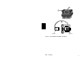
Figure 1 Components for configuration and programming
05
Introduction
25
1.2.1
Hardware
PUTE
Printer
IBM-compatible PCs with hard disk and 640 Kbyte main
memory. A guarantee is only given for AEG devices.
(with parallel interface)
DRU 292/293
DRU 120
DRU 096
DRU 1200
PRT 294/295
EPROM programming station
EPS 2000
Programming adaptor
ADP 001
ADP 004
1.2.2
Software
DOS Version 3.2, 3.3, 5.0
Dolog AKF ® A120 Version 5.0
KOS firmware
26
Introduction
05
1.3
Installation
Installation PRO ® U120
Switch on device (operating system level) Display ”C>”.
05
Step 1
Diskette 1 in diskette drive A or B
Step 2
Installation routine with call ”A:INSTAL” or ”B:INSTAL”,
depending on the drive selected, and start <Cr>.
Step 3
Now follow the instructions of the installation program.
Introduction
27
1.4
New Features
1.4.1
Compared to PRO-U120 V 4.0
Note It is essential that you observe the remarks about the update
version in Part III, chapter 1.5.
Control file
A control file was introduced in Dolog AKF - A120 version 5.0 for the call by
PRO-FWT. This version of the software package PRO ... creates a
corresponding file and thus controls the flow in the call ”Read in ASCII-IL”. The
software package is no longer compatible with older AKF12 versions.
Clock time management in KOS firmware
The message ”Minute pulse missing” can be suppressed with parameters (Part
IV, chap. 2.2.3).
The running reserve for the time management can be set to 1, 26 and 50 hours
with parameters (part IV, chap. 2.2.3).
ALU battery status
The status of the ALU batteries is transferred in the two most significant bits of
the management signal A1 = 0.
8K ring buffer in U120
The firmware diskette contains two new firmware variants in which a ring buffer
of 8K (messages) is implemented. The hardware module KOS 202
(E-No. 278 918) is required here (part IV, chap 2.2.3).
FWM007
FWM008
28
(261 541)
(261 542)
Introduction
SEAB-1F (Modnet 1F)
AWD
05
1.4.2
Compared to PRO-U120 V 5.0
4 master stations for AWD operation
The outstation can now be called with a maximum of 4 master stations (part IV,
chap. 2.2.5).
GA-bits
A GA-bit can be configured for each message (part IV, chapter 2.2.4).
Running reserve
The running reserve can now be set to 5 hours.
05
Introduction
29
1.5
Update version
If you have received an update version of the expert software PRO-U120, you
should pay attention to the following instructions prior to the installation:
As of version 2.0, the software is installed in the subdirectory
”\PRO-FWT\PRO-U120”.
Old versions (1..3) of the expert software will not be overwritten or deleted.
The main menu PRO-FWT will be installed anew and will only call the new
expert systems:
PRO-U120 as of version 4
PRO-Z120 as of version 2
PRO-UZ120 as of version 2
If you also want to call the old versions of the expert systems from a main menu,
you have to save the program PRO-FWT.EXE already installed under a different
name before the installation. The program is located in the root directory.
Example: COPY C:\PRO-FWT.EXE C:\PRO.EXE
The old versions can now be selected by calling PRO.
Data will be saved in a new path and under a new name (see chapter 3.3). If
you want to be able to edit stations created by PRO-Z120, versions 1..3, using
version 4, you have to install the conversion
program included in the package and start it.
Installation instructions:
Insert the disk with the conversion program into drive A or B and start the
installation with A:INSTAL or B:INSTAL.
The program will be installed in the root directory and can be started from there
by entering ”KONVERT”. The conversion only has to be performed once.
30
Introduction
05
Chapter 2
Overview And General
Information
05
Overview And General Information
31
2.1
Summary of Features
PRO ® U120 supports the user in the configuration and start-up of the Geadat
U120 outstation.
A subrack including the module assignment is automatically determined by
specifying the data points
A selected hardware (subrack and I/O modules) and their data point assignments can be selected
Special features can be assigned to the data points
Control blocks can be defined
An instruction list (IL) is generated based on the parameters entered
Transfer of instruction list to Dolog AKF ® A120
Transfer of generated parameters to KOS 201/210 with EPROM or by transfer
to KOS-RAM.
Files can be generated for a bottom-up configuration (e.g. for PRO-Z120,
PRO-UZ120)
32
Overview And General Information
05
Documentation of system by printing
Bill of materials
Hardware configuration
Data point reference list
Table of limits for measurands
KOS 201 parameters
Control blocks
General outstation data
Archiving on hard disk or diskette of the files entered and generated
05
Overview And General Information
33
2.2
Rough structure
Data input (Chap. 5.2)
Project Data
General Datas of Outstation
Number of Data Points
Selection of Subracks
Module and Subrack Assignment
Special Processing of the Data Points
List of Data Points
Edit Library
Archiving (Chap. 5.3)
Read Data
Save Data
Delete File
Change Drive
IL-generation and transfer (Chap. 5.4)
Start IL Generation (German)
Start IL Generation (English)
Create PLC Station And Copy ASCII-IL
Printer output (Chap. 5.5)
Bill of Materials
Hardware Configuration
Table of Measurand Limits, Analog Extreme Values
List of Data Points
General Datas of Outstation, Loading
Control Blocks
All Lists
Selection of Printers
Printer Output to File
Screen Output of Bill of Materials (Chap. 5.6)
KOS 201 Parametering (Part IV)
34
Overview And General Information
05
2.3
Keyboard operation
If a command is specified in pointed brackets < > in the following description,
this means that the corresponding key should be pressed.
<Cr> = Press RETURN key.
<Alt> + <Ctrl> + <Del> = Warm restart, all three keys are pressed
simultaneously.
<F1> ® <F3> = the function keys F1 and F3 are pressed one after the other.
Caution
US keyboard
<Esc>
<Ctrl>
<Home>
<End>
<Prtsc>
<PgUp>
<PgDn>
<Ins>
<Del>
<Return>
German keyboard
<Eing lösch>
<Strg>
<Pos1>
<Ende>
<Druck>
<Figure >
<Figure ¯ >
<Einf>
<Entf> oder <Lösch>
<Übernahme> (auch
<Enter> oder < ¿ >
Function keys
The individual submenues are selected with the function keys.
There is always a return to the previous menu level with <F9>.
Help is always called with <F10>.
05
Overview And General Information
35
Arrow keys (cursor keys)
The parameters are selected or modified in some menues with these keys.
Caution If your PUTE does not have a separate cursor block,
make sure that the key <Num Lock> is switched off as otherwise
the number block is active.
<Return> key
The input in the line editor is terminated or the selected parameter is accepted
with this key.
<Esc> key
There is a return to the previous menu level with this key.
Toggle
Different settings can be selected by pressing the <Return> key repeatedly.
36
Overview And General Information
05
2.4
Mouse operation
The right mouse key corresponds to ESC or F9.
Menu call:
Set the mouse cursor to the red (inverse) function key fields and click with the
left key.
Selection within the menu:
Set the mouse cursor to the desired input line or selection field and click with the
left mouse key.
Set the module or slot location in the menu ”I/O-module selection” in this way
and then delete or set by clicking the red (inverse) function fields.
A selected module can also be entered by twice clicking a subrack location.
File selection window:
Select the system or file with the mouse cursor and click with the left mouse key.
If the mouse cursor is set to the upper or lower free line in the window and
clicked, the scroll function is carried out if necessary.
Setting the mouse cursor to the text RETURN and clicking activates the corresponding RETURN function.
05
Overview And General Information
37
2.5
General information
The following symbol specifies how to select the described function.
Counting always starts with the main menu.
The brackets contain the function keys which must be pressed in the main
menu.
Example:
“Data input”,”Subrack selection”
(F1 ® F4)
The specifications Ex By in the titles are also included in the lower right corner of the screen pages. They display the menu level and menu image.
In this way the relevant chapter for a particular screen page can easily be
found using a cross reference list.
Remark window:
If an incorrect input is made when configuring with PRO ® U120 or if a limit
is exceeded, this is displayed on the screen with the corresponding output. In
order to delete this remark window from the screen, press any key. You can
then correct the input and continue with configuration.
38
Overview And General Information
05
Chapter 3
Overview How To Work
05
Overview How To Work
39
3.1
Flow Chart
Start
1
2
Process new outstation
Module selection
Data point allocation
Comment data point list
Data input
Measurand processing
Archive outstation
Project data
Edit controller
Document outstation
System name and
outstaion numbers
must be entered
Generation of IL
Dolog AKF
A120
Generate EPROM
General outstation data
KOS parametrization
Generate EPROM
Enter number of data point
Insert EPROMs on KOS
and ALU. Set jumper on all
modules. Insert
moldules in subrack
Transfer to
Dolog AKF
A120
End
Subrack Selection
2
1
40
Overview How To Work
05
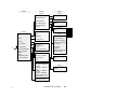
3.2
Tree Structure of the Menues
Level 0
Level 1
Level 2
Figure 1
Project Data
General Datas of
Outstation
Number of Data Points
Selection of Subracks
F1
F2
F3
F4
Modules and Subrack
Assignment
F5
Special Processing
of Data Points
F6
B1
B2
B3
B4
B5
B6
Figure 1
Data Input
Figure 1
Select
Restart
or
Supplement
Data Archive
Generation of IL
and Transfer
Printer Output
Display the Bill of
Materials on the
Screen
Switch
Monochrome/Color
Return to PRO-FWT
Main Menu
F1
F2
F3
F4
F6
List of Data Points
Edit Library
F7
F8
B7
B8
Figure 2
Read Data
Save Data
Delete File
Change Drive
Figure 3
Start IL Generation (GE)
Start IL Generation (EN)
Create PC*Station and
Copy ASCII-IL
Figure 4
Printer Output
Selection of Printers
Printer Output
to File
F9
B9
Figure 6
Output
05
Overview How To Work
41
Level 3
Level 4
Level 5
Figure 1
B1
Input
B2
Figure 2
B3
B4
B5
B6
Input
Figure 3
Input
Presetting
Figure 2
Data Point Input
Input
Figure 4
B7
B8
Figure 1
Select
Figure 3
Figure 5
Module Selection
Data Point Allocation
Input of Data Points
F1
KOS parametering
B1
Figure 6
Measurand Processing
Input
Two-Position Controller
Three-Pos. Controller
Pulse-Width Modulator
Input
Figure 7
B9
Input
Input
Figure 8
Input
Input
Figure 9
Select
42
Overview How To Work
05
Level 5
Level 7
Level 6
Figure 1
Common parameter
SEAB parameter
KOS parameter
List of Assignment
Automatic Polling
Service
F1
F2
F4
Transfer
Printer output
B1
EPROM Menu
Switch
monochrome/color
End of processing
Input
F5
Figure 3
Input
Figure 4
F1
Save
F2
Delete file
F3
F4
F5
Reset PADT Memory
Bottom-up configuration
Figure 2
Read
Figure 1
Archive
Input
F3
Figure 2
Configure parameter
lists
Figure 1
F5
Monitoring direction
Control direction
Change drive
Setpoint value input
Figure 3
Parameter list
from KOS
Parameter list
to KOS
Scan IL Cycle Time
Counted measurand
processing
Ring buffer
handling
Realtime Information
Edge Detection
Figure 4
Printer Output
Selection of Printers
Figure 5
F8
Input
Printer output
to file
Figure 5
Read
Parameter - EPROM
Program
Parameter - EPROM
Read
Firmware - EPROM
Program
Firmware - EPROM
Read Firmware - File
EPROM blank check
Figure 6
Select
Generate export file
Delete PV num.list
05
Overview How To Work
43
3.3
Directory Structure
The TOOL directory PRO-U120 is set up in the main directory PRO-FWT during
installation. The individual programs (EXE files) and the system information for
PRO-U120 are stored there. The subdirectories MACRO and TEXTE are also
set up. These contain the macros for the IL generation or the files with the menu
and help texts, the library and the firmware file.
The files set up by PRO-U120 are stored as follows:
C:\
TEST.PRO
FW
U001-000.HW
U001-000.DPL
U001-000.DPT
U001-000.EST
U001-000.RT1
U001-000.RT2
U001-000.RT3
U001-REG.AWL (IL for control block)
U001-000.AWL
U001-000.EX
U001-000.MES
U001-001.KOM
U005-002.KOM
U001-001.KOS
U005-002.KOS
*.AWD (names are defined
by the user)
EXAMPLE.PRO
FW
U122-000.HW
.
.
.
44
Overview How To Work
05
Explanations about Uxxx-yyy.HW etc.
xxx
yyy
Master station no.
(000-126)
Line number
(001-999)
The number 000 is used for files which contain the data for the whole
master station and which are not assigned to a certain line.
The names of the system directory and the outstation numbers are entered in
the configuration data menu (see chapter 5.2.1). The line numbers are entered
in the ZOOM function.
05
Overview How To Work
45
46
Overview How To Work
05
Chapter 4
Configuration
05
Configuration
47
4.1
Definitions of the Communication Ports
The outstastion is linked to the master station with the KOS 201. It is the link
between the ALU 200/201 and the serial bus SEAB-1F.
The KOS 201 is treated like an I/O module. 128 bytes are provided in each
direction for communications with the ALU 200.
Output byte:
QB x.1 ... QB x.128 transports data from the ALU 200/201 to the KOS 201
(monitoring direction).
Input byte:
IB x.1 ... IB x.128 transports data from the KOS 201 to the ALU 200/201 (control
direction).
x is the KOS slot reference
Note Since the SEAB-1F has a 16-bit structure, 2 bytes are always
combined for one data type. In the following text the term “word” will
therefore always be used.
The 1st word in the monitoring direction is reserved for system information. This
means that only 63 words are available for the data transmission.
The clock time can be transmitted with the corresponding parameter assignment
of the KOS 201 using the last 4 words in the control direction. In this case only
60 words are available for the data transmission.
48
Configuration
05
4.2
Definition of the Data Types
4.2.1
Monitored Information
Configurable at
Allocation
Processing
DEO 216, DEP 208, DEP 216, DEP 296, DEP 297,
DAP 212, DAP 220, DAP 292
In groups of 8 inputs each
No special processing. Two input groups are allocated to
one word and passed to the KOS 201.
Note Transient information must be assigned parameters as
real-time information. If no DCF receiver is connected to the KOS
and no time telegram is sent by the master station, the real-time
information is transmitted with the fine time FFFFH and without
course time telegrams.
4.2.2
Double-point Information
Configurable at
Allocation
Processing
05
DEO 216, DEP 208, DEP 216, DEP 296, DEP 297,
DAP 212, DAP 220, DAP 292
In groups of 8 inputs each
The inputs 1 and 2, 3 and 4, 5 and 6, 7 and 8 of an input
group are checked for a malposition. If there is a
malposition (same state at both inputs), the transfer to the
KOS 201 is suppressed for a certain length of time. This
time can be parametered per outstation. (see also Chap.
5.2.2)
Configuration
49
Note Inputs which are not used should be assigned alternately 0 V
and 24 V, as otherwise malpositions are constantly recognized.
4.2.3
Return Information
Configurable at
Allocation
DEO 216, DEP 208, DEP 216, DEP 296, DEP 297,
DAP 212, DAP 220, DAP 292
In groups of 8 inputs each
The first parametered return information, counted starting
with slot 1, is allocated to the 1st cancelled command, etc.
For reasons of clarity, input and output modules with
return information and cancelled commands should be
inserted next to each other, but this is not absolutely
necessary (see Chap. 4.2.13, Figure 3).
Note The assignment is made by entering <R> and data type
selection “single-point information” or “double-point information”. (DEP
208, DEP 216, DEP 296, DEP 297)
For a DAP 212, DAP220 or DAP 292 the inputs are automatically
interpreted as return information if the outputs are parametered as
cancelled commands. Of course these inputs may not be assigned
parameters as counter measurands in this case. The inputs of a
DAP 212, DAP220 or DAP 292 cannot be used as return information
for other output groups.
Processing
50
Configuration
Return information is treated as single-point informations
or double-point information, depending on the parameter
assignment. A 1 at the input cancels the assigned
command.
05
4.2.4
Real-Time Information
Configurable at
Allocation
Processing
4.2.5
DEO 216, DEP 208, DEP 216, DEP 296, DEP 297,
DAP 212, DAP 220, DAP 292
In groups of 8 inputs each
The real-time information is transmitted to the KOS 201
like normal information. It is stamped there with the time
and stored in the ring buffer.
System Information
Configurable at
Cannot be configured, virtual information.
Allocation
Is always assigned to the 1st word in the monitor direction
and has the subaddress (A1-byte) 0.
Processing
The system information contains the following information:
Module disturbed (1-18 binary coded) bit 20 to 24.
More than one module failed bit 25 = 1.
No return information for last actively cancelled command
bit 26 = 1.
Note You can also transmit the faulty or disturbed modules n of 18
coded to two further system information telegrams. This system
information has the subaddress 1 (slots 1 to 16) and subaddress 2
(slots 17 and 18). This information is configured in the menu “General
Outstation Data”.
05
Configuration
51
4.2.6
Counted Measurands
Configurable at
DEO 216, DEP 208, DEP 216, DEP 296, DEP 297,
DAP 212, DAP 220, DAP 292
Allocation
In groups of 8 inputs each. The number of inputs actually
required is also specified.
Processing
The counter measurands are formed in the IL. Counter
pulses of 20 Hz are possible, but depend on the IL scan
time. First there is a check of the edge. The allocated
marker word is incremented for each rising edge of the
pulse input. It is reset to 0 when the value 65535 (FFFFH)
is reached.
Caution For counted measurand processing, the ALU201 must
be used with a backup battery so that the counter states are not
deleted if there is a power failure.
4.2.7
Measurand 8 Bits without Sign
Configurable at
Allocation
Processing
ADU 204, ADU 205, ADU 206
Depending on module. The number of actually required
inputs is also specified.
The measurands are formatted left-justified in a function
block. Only positive measurands are transmitted. Negative
measurands are set to 0.
Note If the ADU 206 is used, a measuring range of 1V or 10V can
be set for each of the 4 measurand inputs. The ADU 206 already
provides left-justified measurands. Therefore there need only be a
limitation to +32000.
52
Configuration
05
4.2.8
Measurand 11 Bits with Sign
Configurable at
Allocation
Processing
ADU 204, ADU 205, ADU 206
Depending on module. The number of actually required
inputs is also specified.
The measurand is formatted left-justified in a function
block and limited to +32000. This corresponds to a scale
end value of + 2000.
Note If the ADU 206 is used, a measuring range of 1V or 10V can
be set for each of the 4 measurand inputs. The ADU 206 already
provides left-justified measurands. Therefore there need only be a
limitation to +32000.
4.2.9
1-Pole Commands
Configurable at
Allocation
Processing
05
DAO 216, DAP 204, DAP 208, DAP 216
DAP 212, DAP 220, DAP 292
Depending on outstation
A command from the master station controls an output.
Configuration
53
4.2.10
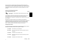
2-Pole Commands
Configurable at
Allocation
Processing
DAO216, DAP204, DAP208, DAP 212, DAP216, DAP220,
DAP292
Depending on substation
DAO 216, DAP 216 A command from the master station
controls 2 outputs of a DAO 216 or DAP 216. Output 1
and 9, 2 and 10, 3 and 11 etc. form a 2-pole command.
Caution The 2-pole output is only possible by connecting an
interface relay between the end relay and the output module.
Processing
DAP 204, DAP 212 A command from the master station
controls 2 outputs. Output 1 and 2, 3 and 4 each are one
2 pole command.
Processing
DAP 208 A command from the master station controls 2
outputs. Outputs 1 and 2, 3 and 4, 5 and 6, 7 and 8 each
are one 2-pole command.
DAP 204/212/292
DAP 208
DAP 216
Command 1
Command 1
Command 2
Command 3
Command 2
Command 1
Command 2
Command 3
Command 4
Figure 2 2-pole command output on DAP 204, 212 and 216
54
Configuration
05
Note A 1 of n check is made before each command output. No
further command can be output as long as one command is running.
Commands which arrive during the command runtime are lost.
Three possibilities exist for processing the above-mentioned command types:
Pulse commands (commands whose output time can be parametrized)
Persistent commands
Actively cancelled commands
The type of processing can be assigned to an output group of 8 outputs
(DAO 216, DAP 216) or by module (DAP 204, DAP 208, DAP 212, DAP 292).
4.2.11
Pulse Commands
The output time can be assigned parameters depending on the output group. A
timer with the parametrized output time is set and started as soon as a
command is output. The command output is reset when the timer has expired.
4.2.12
Persistent Commands
One time for spanning the telegram runtimes is parametrized for each outstation.
A timer with the parametrized time is set and started as soon as a command is
output. The command output is reset when the timer has expired.
In contrast to the pulse commands, the timer is repeatedly reset and restarted by
sending the same command.
05
Configuration
55
4.2.13
Actively Cancelled Command
A cancel supervise time and a cancel link time is parametrized for each
outstation.
A command is output until the assigned return information arrives or the cancel
supervise time has expired. The command is not immediately reset after arrival
of the return information, but only after expiration of the cancel link time.
If a command was not cancelled by its return information, but was reset after
expiration of the supervise time, bit 26 in the organization information word is
set.
Note Actively cancelled commands cannot be configured for the
DAP 204.
The return information is assigned as described in Chap. 4.2.3.
There is 1:1 assignment for 1-pole commands.
8 information inputs of a DEP 208 or DEP 216 are used as return information for
2-pole commands on DAO 216 or DAP 216.
The first two pieces of monitored information from the same module are used as
return information for 2-pole commands on DAP 212 or DAP 292.
56
Configuration
05
DAP 212/292
DAO 216
DAP 216
DEP 216
DEP 296
DEP 297
CACO
CACO
SPIR or DPIR
SPI
or
DPI
CACO
SPIR or DPIR
Figure 3 Assignment of Cancelled Commands and Return Information
4.2.14
Digital Setpoint Values
Configurable at
Allocation
Processing
05
DAP 216, DAO 216
Depending on module
No special processing. The 16-bit value is output on 16
outputs.
Configuration
57
4.2.15
Analog Setpoint Values
Configurable at
Allocation
Processing
DAU 202, DAU 208
The number of setpoint values is configured.
No special processing.
Note Make sure that the valid range of +32000 is not violated by
the master station.
58
Configuration
05
4.3
Configuration Limits
Table 1 Configuration Limits
Data type
Number
Structure
Monitored information
Real-time information
Counter measurands
Measurand 8 Bit
Measurand 11 Bit
Organization information
1-pole/2-pole commands
Digital setpoint values
Analog setpoint values
256
256
63
64
63
48
256/128
16
32
Bit
Bit
Word
Byte
Word
Bit
Bit
Word
Word
The specified numbers are single limits. The total limits result from the sytem
limits such as the capacity of the communications port (EB/AB each 128 bytes)
and the equipment conditions.
05
Configuration
59
4.4
Special Features
The KOS 201 can only be used in the central subrack.
Clock antenna DCF77E can only be used for KOS 201.
Gaps can occur in the module addressing if a bus extension cable is used.
Only DTA 201 can be used as a secondary backplane if a bus extension
cable is used.
Use for measurand processing ALU 201 or backup battery control gear.
PRO-U120 does not support the measuring range spread set with a control
byte and the setting of unipolar measurands possible with the ADU 206.
The name KOS 201 refers to the mode resp. ident code of the KOS.
KOS 201 = ID-Code 90 ® 128 I/O-bytes
However, you can also use the KOS 202 as hardware.
With the FWM 007/008, you have to use the KOS 202 as hardware. (a variant
with 8 kB ring buffer store)
60
Configuration
05
Chapter 5
Handling
Configurating, parametering and programming with PRO ® U120
is described in this chapter.
This chapter is a reference manual for the person configuring. Its
structure corresponds to that of the menues.
05
Handling
61
5.1
General Information
The individual menu points are described in the order listed below.
62
Data input
Chapter 5.2
Data archive
Chapter 5.3
IL generation and transfer
Chapter 5.4
Printer output
Chapter 5.5
Screen output of the bill of materials
Chapter 5.6
Handling
05
5.1.1
The Line Editor
The line editor is used for inputting project data, commenting the data point list
and extending the library file.
Table 2 Keyboard Definition (US-Keyboard)
Key
Definition
¬ (Backspace)
<Del>
<Ins>
Delete character to the left
Delete character above cursor
Insert/overwrite switch (is displayed to the right
in the last screen line)
Cursor to first character of input line
Cursor to last character of input line
Cursor one position to left
Cursor one position to right
Cursor to start of previous input line
Cursor to start of next input line
Terminate input
<Home>
<End>
<¬>
<®>
<>
<¯>
<Cr>
Only for data point list, library and bill of materials
<PgUp>
Previous page
<PgDn>
Next page
Only for data point list
<Alt>+<M>
<Alt>+<A>
<Alt>+<E>
<Alt>+<C>
05
Mark a line to copy
Mark line block, start
Mark line block, end
Copy marked line or line block to current cursor position.
Handling
63
Since many computers are equipped with a US keyboard, the special German
letters were assigned to function keys.
<Shift>+<F1>
<Shift>+<F2>
<Shift>+<F3>
<Shift>+<F4>
<Shift>+<F5>
<Shift>+<F6>
<Shift>+<F7>
<Shift>+<F8>
<Shift>+<F9>
<Shift>+<F10>
=
=
=
=
=
=
=
=
=
=
Ä
Ö
Ü
ä
ö
ü
ß
|
<
>
Additional columns can be set up in the comments part of the data point list with
<Shift>+<F8>.
Note The complete set of characters can be edited with
<Alt>+<ASCII-keyboard code>. The number sequence may only be
entered using the numeric block.
The corresponding tables can be found in the PUTE user manual or
in the printer manual.
Example:
The letter Ä should be input with the keyboard code. Press the Alt key and then
the digits 1, 4 and 2 one after the other. Release the Alt key and the Ä appears
on the screen.
64
Handling
05
5.1.2
Start of PRO ® U120
E0 B1
PRO ® U120 is started from the main menu PRO ® FWT. A header which defines the current version of the operating software appears once after the call.
The main menu PRO-U120 appears after any key is pressed and you can begin
configuration.
PRO ® U120 loads the last processed system and station into user memory after the call.
Caution The system “NONAME” and the station “U000-000” are
set by the installation routine during the first start.
If the loaded station is to be processsed, one must decide whether the data
model should be regenerated or only supplemented. The data model should
always be regenerated as long as it is not passed to a master station.
Caution If the data model of an outstation has already been accepted in a master station, please only continue processing with
“supplement” as otherwise the data model of the master station
also must be changed.
Warning Supplementing means that the data points are included. Data points which already exist may not be modified or
deleted as this results in chaos in the data model. Deletion or
modification is only possible in “restart” mode.
05
Handling
65
5.1.3
Autosave
Before leaving certain submenues, the data edited or generated there are stored
on hard disk. In particular these are the menues:
Data input
Number of data points
Module select
Measurand processing
Control blocks
Data point list
Edit Library
Generate IL
Display of the bill of materials on the screen
66
Handling
05
5.2
Data Input
E1 B1
Note Modification of the module or data point assignments is only
possible in restart mode. The same is valid for deleting modules or
data points.
Empty slots can be assigned modules in the supplement mode.
Similarly, inputs or outputs can be defined on already existing
modules for which no data was previously assigned. These new
entries can be modified and deleted within a supplementary run. If
the station is processed again in “supplement” mode, these data also
have write protection.
5.2.1
Project data
E2 B1
”Data input”,”Project data”
(F1® F1)
The last date of station processing is displayed. The user cannot change this
line.
System
E3 B1
An input of at most 8 characters is required. The system name is at the same
time the name of the subindex in which the data of the outstation are archived
(see Chap. 3.3). For this reason only characters which are permitted as index
names under DOS may be input.
Outstation, Comments, Operator
A maximum of 16 characters may be input. All characters which can be
displayed may be used (see Chap. 5.1.1).
The specifications define more exactly an outstation. They are printed in the
documentaiton in the form of a header.
05
Handling
67
Outstation number
It is also called the outstation address or A-Byte for the SEAB-1F. An outstation
number between 0 and 126 must be entered. It is also used to identify the
individual files during archiving (see Chap. 3.3).
Note You can copy the station set by overwriting the system name
or the outstation number. First, however, it must be stored with the
“data archive” menu.
Example:
System “EXAMPLE” and outstation-No. “0” are loaded and should be copied to
“EXMAPLE\U005-000”.
Step 1
Overwrite UST-No. “0” with a “5”.
Step 2
Leave menu with <F9> or <Esc>.
Step 3
Interrogate if outstation should be copied. Answer with
<J> <Cr>.
Step 4
Outstation is copied.
If you answer step 3 with <N> <Cr>, the system “EXAMPLE” outstation-No. “0”
is not copied but “EXAMPLE\U005-000” is opened as the new station.
Note If the station “EXAMPLE\OST5” already exists, the
corresponding message appears on the screen. You can now decide
whether the archived data should be overwritten or loaded into user
memory.
In the same way you can copy “EXAMPLE\U000-000” to “TEST\U003-000” by
overwriting the system names and the outstation number.
You can then modify and supplement the corresponding menues.
68
Handling
05
5.2.2
General Outstation Data
E2 B1
”Data input”,”General outstation data”
(F1® F2)
The values set in this menu are valid for the entire outstation.
IL in Monitoring Direction
The information is transmitted in monitoring direction to both KOS modules in
each IL scan. The 128 output bytes of the 1st KOS are copied in a program
block to the 128 output bytes of the 2nd KOS. Bytes which are not used a re
also copied.
IL in Control Direction
To prevent setpoint values from two master stations from colliding with each
other, a control command defines whether the data of the 1st or 2nd KOS are to
be processed in the IL. This command message is transmitted in input bytes 1
and 2 to the IL and must set the 1st bit in the IB x.1. The IL checks these bytes
in each scan. The commands and setpoint values of the last master station to
send this control command are output.
After a cold restart, the 1st KOS (left) is taken as default KOS until a
corresponding control instruction is set by one of the master stations.
PRO-U120 offers the next free group as command group. The first command of
this group is the control command. The group number, however, can be changed
in the KOS parametrization in the “Data for Control Direction” menu.
The command is computed from: (group number * 16) + 1
Example:
IB 2.1 BE
IB 2.3 BE
IB 2.5 BE
02
00
01
(control comand byte)
(single commands)
(single commands)
Command 33 is the control command in this example.
05
Handling
69
Caution Make sure that a master station may only send a control command when it is ensured that all the setpoints in the
particular KOS have the current state.
Command type
One can choose 1-pole or 2-pole command output by toggling.
E3 B2
For 1-pole command output, a command from the master station controls one
output of an output module.
For 2-pole command output, a command from the master station controls one
output each of the upper and lower output groups for the DAP 216. Outputs 1
and 9, 2 and 10, 3 and 11 etc. thus each form a 2-pole command. For the DAP
204 and DAP 212, the outputs 1 and 2 as well as 3 and 4 each form a 2-pole
command.
Cancel link time
Setting range:
Standard setting:
E3 B2
100 msec to 99.9 sec
200 msec
The arrival of the return information starts the timer for the cancel link time. The
command output to be cancelled is reset after expiration of this timer.
70
Handling
05
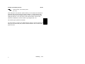
Cancel supervise time
Setting range:
100 msec to 99,9 sec
Standard setting:
30 sec
E3 B2
As soon as a command with active cancellation is output, the timer for the cancel supervise time is also started. If the return information does not arrive, the
command output is reset after expiration of this timer. If this case occurs, bit 26
in the organization information word is set.
E
TV
TÜ
A
E
TV
TÜ
A
=
=
=
=
Input of return information
Cancel link time
Cancel supervice time
Command output
Figure 4 Time diagram for actively cancelled commands
Malposition suppression time
Setting range:
100 msec to 99,9 sec
Standard setting:
20 sec
E3 B2
The transmission of the malposition is suppressed for this time span for
double-point information. If both monitoring information inputs have the same
state, the timer for the malposition supervision time is started.
If a further malposition occurs during the timer execution time, the timer is reset
and started again immediately. After expiration of the timer, the malposition is
transmitted to KOS 201.
If the malposition is corrected, i.e. the monitoring information input changes its
state, the timer is reset. The information change is immediately transmitted to
KOS 201.
05
Handling
71
If several malpositions occur at the same time, the timer can only be reset by
correcting the last malposition.
Caution Double-point information inputs which are not used
should be assigned alternately the levels 0 and 1 as otherwise
they are interpreted in the IL as malpositions and constantly
start the timer for the supervise time.
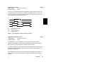
E1.1
E1.2
T
M1
M2
E1 und E2 =
T
=
M1 und M2 =
Double-point information inputs
Malposition suppression time
Information status which is tranferred to master station
Figure 5 Time diagram for malposition suppression
72
Handling
05
Delay time for persistent commands
Setting range:
100 msec to 99,9 sec
Standard setting:
2 sec
E3 B2
This delay time spans the telegram operating times between the outstation and
the master station.
If a consistent command is sent by the master station, the timer for the delay
time is started. If the same command arrives again during the timer operating
time, the timer is reset and started again immediately. The command output is
only reset when the timer has expired.
B
T
A
B
T
A
=
=
=
Command from master station
Delay time
Command output
Figure 6 Delay time for persistent commands
Reserved Words in Monitoring and Control Direction:
E3 B2
You can reserve “transport capacity” for virtual data or for process data which
you keep in a separate part of the IL. The number of words to be reserved can
be specified but not their position on the ALU-KOS-interface. The reservation is
made in monitoring direction after the first word required for the status transport
or after the third word if “module failure information n of 18” was configured.
Reservation starts with the first word in control direction. The area thus defined
is not used by PRO-U120 during generation of the IL.
The EB/AB area of KOS which is reserved is auatomatically displayed when
your input is terminated with <Cr>.
05
Handling
73
Note The reserved area of EB/AB can be defined “manually” with
the KOS parameters.
Module failure information
Failed terminals are reported in the organization information with the subaddress
0. If several terminals fail, only the one with the highest slot address is reported.
Since is some cases this is not sufficient, you can set here that the failed I/O
terminals should be reported coded n of 18. 2 organization information telegrams
with subaddress 1 (slots 1 - 16) and subaddress 2 (slots 17 and 18) are
generated for this purpose. The setting is made by toggling.
1st Module location
®
2nd
Module location ®
18th
.
.
.
Module location ®
Subaddress 1, D2.0
ABx.3, Bit 20
Subaddress 1, D2.1
ABx.3, Bit 21
Subaddress 2, D2.1
ABx.5, Bit 21
x = Slot reference KOS
DCF-Receiver
You can specify whether or not the KOS 201 should be equipped with a
DCF-receiver. The setting is made by toggling.
74
Handling
05
5.2.3
Number of data points
E2 B1
This menu contains the call for two more submenues.
E3 B2
Presetting
Data point input
PRO ® U120 determines the required number of subracks and I/O modules using the input and preset data.
PRO ® U120 makes an equipment suggestion which you can change in the
menues “subrack select” and “module select”.
Note It is recommended that you take this sequence of suggestions
into consideration in the initial system concept and then not change
it.
05
Handling
75
Presetting
E4B1
”Data input”,”Number of data points”,”Presetting”
(F1® F3® F1)
Note You can display Helptext about all interrogations in this menu
by selecting the corresponding line or setting and calling the Helptext
with <F10>.
Central processing unit
You can toggle the ALU types ALU 200 and ALU 201. If ALU 201 is set, the
power supply DNP 205 is automatically taken into consideration in the slot
assignment.
Output voltage
You can toggle between 24 V and 60 V peripheral voltage. If the peripheral
voltage is 60 V, the commands are automatically output to the relay module DAP
212.
Note The display for “Output via relay” cannot be changed if there
is 60V peripheral voltage.
Additional Power Supply
If a 24 V input power supply is not available, you can include additional power
supplies. PRO ® U120 provides the following three modules:
DNP 220
DNP 260
BAC 224
The setting is made by toggling.
76
Handling
05
Output with relays
You can choose whether or not commands should be output via relays for a
peripheral voltage of 24 V. If the peripheral voltage is 60 V, output is always via
relays. The setting cannot be toggled in this case.
Measurands
You can set whether the measurands should be input isolated or non-isolated.
Data point input
E4B2
”Data input”,”Number of data points”,”Data point input”
(F1® F3® F2)
Input:
E3 B3
The input must be decimal and terminated with <Cr>. The following upper limits
are monitored:
Maximum number of I/O modules
Capacity of ALU-KOS interface exceeded
Maximum number of data points for this data type
If one of these limits is exceeded, the corresponding message is output on the
screen and the input is not accepted.
The number of reserved slots is displayed at the lower end of the screen.
Similarly, the free slots are displayed based on the maximum configuration of 18
slots.
Note The selection of I/O modules is limited for this function to:
ADU 205
ADU 206
DAU 202
DEP 216
DAP 216
DAP 212
05
Handling
77
Since information and commands only can be reserved in groups of 8 or 4, it is
automatically rounded up when you leave the menu. Don’t be surprised therefore
if your definitions have been changed when you select this menu again.
When assigning the data points to the I/O modules PRO ® U120 proceeds as
follows:
1.
Pulse commands
2.
Single-point information
3.
Double-point information
4.
Real-time information
5.
Measurands
6.
Digital setpoint values
7.
Analog setpoint values
8.
Measurand 8 Bit
9.
Measurand 11 Bit
Caution If you made changes or extensions with the menues
“subrack select” or “module select”, you should not select this
function again. PRO ® U120 overwrites your entries with its
“suggestion”.
78
Handling
05
5.2.4
Subrack select
E2 B1
”Data input”,”Subrack select”
(F1® F4)
Selection:
E3 B4
The selected subracks are displayed inversely. You can change the setting with
<
¯
> or < >.
If an existing selection is “reduced”, any I/O modules are deleted.
You are informed if this is the case so that you can retract the change.
You can set whether or not a bus extension cable should be used with <® > or
<¬ >.
Note If a bus extension cable and 2 or 3 subracksare used, the slot
distribution is not continuous. Gaps occur in the addressing. The
subracks are displayed appropriately in the menu “module select”.
When leaving the menu with <F9> or <Esc>, the selected subracks are included
in the configuratino of the station.
05
Handling
79
5.2.5
Module and Subrack Assignment
E2 B1
”Data input”,”Module and subrack assignment”
(F1® F5)
Selection:
E3 B5
The subracks are displayed graphically according to the setting in the menu
“subrack select” or with the preset values in the menu “number of data points”.
Since not all the subracks have room on the screen next to each other, they are
displayed in two rows, one below the other.
However, this does not mean that a bus extension cable must be used. If you
configure a bus extension cable, it will be displayed as a connection between the
upper and middle subrack.
The 3rd top hat rail should enable the user to configure additional power
supplies or interface relays etc. No I/O modules may be entered there because
the ALU can only address a maximum of 4 subracks with 18 I/O slots.
There is a window with the I/O modules, the communications processor module
and the power supply on the left side of the screen.
The Helptext for the selected module to the left in the window can be called with
<H>.
The individual modules are selected with < > and < ¯ >, the subrack slot is
selected with < ¬ > and < ® >. An arrow indicates the current position.
The set module is entered in the selected subrack slot with <Cr>.
A plausibility check whether this entry is valid is carried out. If this is not the
case, a message is output and the entry is not made.
Furthermore, the power load of the 5 V and 24 V power supply is monitored. If
for example the maximum of 700 mA, with which the 5 V power supply of the
ALU 200 can be loaded, is exceeded, the appropriate message is output. In this
case you can only use the ALU 201 together with the power supply DNP 205
(max. 2 A).
80
Handling
05
The module can be deleted from the marked slot with <Del>.
Note If you are working in “supplement” mode, modules which were
assigned data points during previous processing are not deleted or
overwritten.
The module which is set in the subrack can be marked for copying with
<Alt>+<M>. This is displayed with a * at the lower edge of the module.
A marked module including the data point assignment can be copied to the set
subrack slot with <Alt>+<C>.
05
Handling
81
Survey
”Data input”,”Module and subrack assignment”,”Survey”
(F1® F5® F8)
The number of configured data points as well as the assignment of the KOS-I/O
area (unused words in monitoring and control directions) are displayed in a
window. Similarly, unused digital and analog inputs and outputs are displayed.
If digital inputs of counter measurand data type were assigned to a group of 8
and a value less than 8 was specified as number, these unused digital inputs are
marked specially as “unused counter measurand inputs”.
The computed load of the 5V and 24V power supply is displayed in a second
window which appears when a key is pressed. Similarly, the maximum load of
the 5V power supply defined by the ALU 200 or DNP 205 is displayed. If one of
the provided mains DNP 220, DNP 260, BAC 224 was configured, the maximum
load of the 24V power supply is also displayed.
Note This summary can also be called from the ZOOM menu with
<F8> or from the main menu with <ALT>+<U>.
82
Handling
05
ZOOM on/off
E4 B3
”Data input”,”Module and subrack assignment”,”ZOOM on/off”
(F1® F5® F1)
Once the I/O modules have been allocated, they can be assigned data points.
Zooming is possible here, i.e. an I/O module can be displayed enlarged. The I/O
module marked to the right in the subrack is displayed to the left in the figure.
In order to display another module, the slot in the subrack must only be changed
with <¬ > or <® >. You need not leave the “ZOOM” function.
The relevant I/O module is displayed graphically in the window which was
opened by the ZOOM function. The valid data point types are listed to the right
of it. (see Chap. 4.2)
These are:
Single-point information
Double-point information
Real-time information
Counter measurands
Measurands 8 Bit
Measurands 11 Bit
Actively cancelled commands
Persistent commands
Pulse commands with command runtime
Digital setpoint value output
Analog setpoint value output
The individual modules are displayed subdivided into data groups.
Monitored information and counter measurands are assigned in groups of 8
inputs.
Commands are assigned by module or in groups of 8 outputs.
Analog and digital setpoint value output as well as measurands are assigned by
module.
05
Handling
83
DEP 208 subdivided into 1 x 8
DEO 216 subdivided into 2 x 8
DEP 208 subdivided into 1 x 8
DEP 216 subdivided into 2 x 8
DEP 296 subdivided into 2 x 8
DEP 297 subdivided into 2 x 8
DAO 216 subdivided into 2 x 8
DAP 212 subdivided into 1 x 4 and 1 x 8
DAP 292 subdivided into 1 x 4 and 1 x 8
DAP 216 subdivided into 2 x 8
DAP 220 subdivided into 1 x 8 and 1 x 8
ADU 204 subdivided into 1 x 4
ADU 205 subdivided into 1 x 4
ADU 206 subdivided into 1 x 4
DAU 202 subdivided into 1 x 2
DAU 208 subdivided into 1 x 8
The individual connect groups are selected with <Home> and <End>.
The data types are set with < > and < ¯ >.
The selected data type is passed to the connect group with <Cr>.
An assigned data type can be deleted with <Del>.
Note When working in “supplement” mode, data points which were
configured during previous processing cannot be deleted or
overwritten.
For pulse commands, a command runtime (command duration) can be assigned
per output group. Times between 100 msec and 99,9 sec are possible. The
standard setting is 300 msec. The runtimes for persistent commands and
actively cancelled commands are assigned in the menu “general outstation data”
(see Chap. 5.2.2).
Connect groups with 8 or 4 inputs are always defined for counter measurands
and measurands, but the number of inputs actually used must also be specified.
Analog setpoint value outputs are handled in the same manner.
84
Handling
05
The number or command runtime must always be input if the corresponding
query is displayed inversely in the ZOOM window.
If an ADU 206 was selected for the measurand processing, a measuring range
of 1V or 10V can be selected for each of the 4 measurand inputs. The selection
window can be called with <*>.
You can identify single-point or double-point information as return information for
actively cancelled commands by entering <R> before the <Cr>. The information
group is entered in the window with ”ME R” or ”DMER”. The setting ”R” is
maintained until the data type or module is changed.
Note Special function for linking to master stations Geadat VEN.
An 8-input monitored information group can be specially marked by
entering < N > (N = new subaddress) so that it can be assigned to a
specific new SEAB-telegram. This monitored information group is displayed in the window with ”SPIN”.
The setting ”N” is maintained until the data type or module is
changed.
Caution When assigning counter measurands, measurands and
analog setpoint value outputs, one should make sure that there
are no gaps in the assignment.
05
Handling
85
ADU
204
ADU
204
ADU
204
ADU
204
ME8
2
ME8
3
ME8
4
ME8
1
wrong
correct
Figure 7 Data point assignment
You can process unused counter measurand inputs, measurand inputs and
analog outputs in a separate IL part if necessary.
This is not valid for monitored information inputs and command outputs because
these are always processed by the “generated IL”. If these inputs and outputs
are processed with one’s own IL nevertheless, one must make sure that there is
no collision with the generated IL. The generated IL must be changed if
necessary.
Warning An IL generated with PRO ® U120 is supplemented
with user-dependent PLC functions according to the
Dolog AKF ® A120 rules.
If the blocks generated by PRO ® U120 are changed, no
guaraantee can be made that these changed blocks will function
correctly.
The following upper limits are checked after each data point assignment:
maximum number of data points per data type
capacity of the ALU-KOS-interface
power load of the 24 V and 5 V power supply
86
Handling
05
A message appears on the screen if an upper limit is exceeded and the
assignment is not made.
You can call a survey of the assigned data points with the function key <F8>
(see Chap. 5.2.5).
Peculiarities when zooming the KOS:
The module KOS 201 has a special status. No data points are assigned here in
the ZOOM function; instead the parameter assignment program is called and the
line numbers and possibly an additional module are entered. The input of a line
number is necessary for the bottom-up configuration in order to make a
connection between the outstation and the master station or subst ation. The line
number also defines the file names for storing the KOS parameters.
The descriptions of these parameter assignment programs can be found in
Part IV.
The call becomes active with <Cr>. The line number is entered in decimal
between 1 and 999. The additional module is set by toggling. If you do not want
to call the parameter assignment program, move the cursor in the subrack on by
one slot. However, this is only possible if the cursor points to the uppermost line.
The KOS parameter assignment program can also be called from the main
menu with <Alt> + <K>. If several KOS modules were equipped, the KOS
parameter assignment is called with the lowest slot reference.
Before the KOS main menu appears, there is a query whether the KOS
parameters should be newly defined or whether they should keep the old data.
If the KOS file is newly defined, the standard settings are made for the transfer
bit, ring buffer entry, edge detection, etc.
If you made not changes to the data points, you can call the KOS parameter
assignment without generating a new file. Your settings made in a previous call
are not changed.
05
Handling
87
Several KOS modules in one outstation
Maximum number of KOS modules:
3 KOS for central processing unit ALU 200
2 KOS for central processing unit ALU 201
If more than one KOS is configured in an outstation, the KOS with the lowest
slot reference is used for the generation of the IL. However, the same parameter
as the “IL-KOS” is passed to the other KOS modules.
The parameter assignment for the 2nd or 3rd KOS can only be called by
selecting and zooming the corresponding module in the “module and subrack
assignment” menu. The outstation number entered in the “project data” menu is
passed to all KOS with the first call of the parameter assignment program. You
can change this as well as the other parameters as you wish. It is also possible
to supplement or delete data type assignments in the “Data for monitored
direction” or “Data for control direction” menues.
Note You must impelement the processing of the 2nd or 3rd KOS in
a separate IL part.
88
Handling
05
Special remark for equipping command output modules:
2 types of modules are provided for command output: relay modules with 4
outputs each and semiconductor modules with 2 x 8 outputs each.
If it should be necessary to drive a combination of 4-output and 8-output
modules in one station, they should be sorted before entering in the subrack.
In order to avoid gaps in the commands, the relay modules should be entered
following the semiconductor modules.
The 4 outputs are combined when the input bytes of the KOS are assigned and
thus in the data model, but an 8-output module is not “taken apart” and stored in
different input bytes.
For reasons of clarity it is recommended that cancelled command output on
semiconductor modules and the associated return information modules be
adjacently equipped.
mal
DAP DAP DAP
204 216 216
better
DEP
216
DAP
212
PUCO CACOPUCO SPIR CACO
4
8
8
8
4
CACO PUCO SPIR
8
8
8
Command No.
1-4
9-24 25-40
Command-group No.0
0/1
1/2
Information group No.
gap
0
SPI
8
41-44
2
1
DEP
216
DAP DAP
216 216
DAP
212
DAP
204
SPIR CACOPUCO CACO PUCO
8
8
8
4
4
SPIR CACO PUCO SPI
8
8
8
8
0
1-16 17-32 33-36 37-40
0
1
2
2
1
Figure 8 Equipment suggestion for command output modules
05
Handling
89
5.2.6
Special Processing of Data Points
Measurand processing
E3 B6
E4 B4
”Data input”,”Special processing of data points”,”Measurand
processing”
(F1® F6® F1)
All the measurands configured in the “module select” menu are listed. Each
single one can be assigned an upper and a lower limit to be monitored and a
hysterese.
Limits from -32000 to +32000 for 11-bit measurands and from 0 to +250 for 8-bit
measurands are possible. The hysterese is defined as an absolute value between 0 and 32000/250 and is valid for the upper and lower limits.
Two items of virtual monitored information are assigned to each measurand to
be monitored during generation of the IL. One each is assigned for the upper
and lower limit, even if only one limit is to be monitored. The virtual monitored
information is assigned to the measurands in the order in which it occurs.
If the “supplement” mode of processsing is selected, limits which are entered
later do not change the original order of the monitored information. The new
monitored information is appended. The virtual monitored information for the limit
monitoring begin with SEAB subaddress 32 (20H).
90
Handling
05
lower limit value
upper limit value
1
0
--32000
+32000
Hysteresis
0 - 1 edge
2. information
1 - 0 edge
2. information
0 - 1 edge
1. information
1 -- 0 edge
1. information
Figure 9 Limit monitoring of measurands
Input of the limits:
The current input field is displayed inversely. One reaches the next or previous
input field (with stacked drop layout) with <Tab> and <Shift> + <Tab>.
One reaches the next or previous input field of a line with <Ctrl> + <® > and
<Ctrl> + <¬ >.
Otherwise the requirements of the line editor are valid.
A message appears on the screen if a value less than -32000 / 0 or greater than
+32000 / 250 is input and the value must be corrected.
Analog Extreme Values
E4 B5
“Data Input”, “Special Processing of Data Points”, “Analog Extreme
Values”
(F1 ® F6 ® F2)
All the configured 11-bit measurands are listed in this submenu. The software
address with which a measurand is addressed under Dolog AKF is specified.
This does not correspond to the hardware address. The definition 03.01
05
Handling
91
specifies the 1st measurand of an ADU at slot 3. 4 hardware connections of Pin
3...6 are assigned to this measurand.
You define the measurand for which extreme values should be determined by
toggling with <Cr>.
There is also a query whether a maximum or minimum extreme value is
required. It is also possible to determine both extreme values. This means,
however, that both extreme values are determined and transmitted to the KOS
for all the selected measurands.
One time interval which is also interrogated in this menu is valid for all extreme
values.
Time interval:
Minutes 1,2,3,4,5,6,10,12,15,20,30
Hours 1,2,3,4,6,8,12,24
Extreme values are transmitted like “normal” measurands in the SEAB-1F.
Identification is thus with the A1 byte. To prevent overlapping in extensions, the
extreme values are sorted in decreasing order starting with A1 = 63.
The extreme values are displayed with “MWE” in the menu “Data Monitoring
Direction” of the KOS parameter assignment.
Processing
The measurand the the relevant extreme values are compared in the IL in each
scan. If the measurand is greater than the upper or smaller than the lower
extreme value, it is transmitted to the KOS as the new extreme value.
Caution If analog extreme values are to be determined, the
clock time must be transmitted to the KOS.
The clock time passed to the KOS by DCF signal or time message is transmitted
in the EB area of the KOS. This time is used by the IL to standardize the
temporary extreme value storage synchronously with the KOS.
92
Handling
05
Two-position controller
E4 B5
”Data input”,”Special processing of data points”, ”Two-position
controller”
(F1® F6® F2)
If the difference between the setpoint value (WE) and the actual value (XE)
exceeds half the hysteresis value (HYS), the output (YA) is set depending on the
sign of the deviation. The controller can be released with the release enable (EF
= 1) and is reset with the reset enable (ER = 1).
You can set the time intervals in which the controller module should be executed
using the clock pulse time (TA). If the controller is to be executed in each IL
scan, enter the constant 0.
Clock pulse time (TA) = Constant * 100 ms
Three-position controller
E4 B6
”Data input”,”Special processing of data points”, ”Three-position
controller”
(F1® F6® F3)
If the difference between the setpoint value (WE) and the actual value (XE)
exceeds half the hysterese value (HYS), the output (YP or YN) is set depending
on the sign of the control deviation. A neutral zone (UZ) can be entered as well.
The output is reset when the value is less than the corresponding inner edge.
Overlapping of the hysteresis up to HYS = 2*UZ is possible.
The controller is released with the release enable (EF = 1) and reset with the
reset enable (ER = 1). You can set the time intervals in which the control block
is to be executed with the clock pulse time (TA). If the controller is to be
executed in each IL scan, enter the constant 0.
Clock pulse time (TA) = Constant * 100 ms
05
Handling
93
Pulse width modulator
E4 B7
”Data input”,”Special processing of the data points”, ”Pulse width
modulator”
(F1® F6® F4)
The pulse width modulator converts a numeric control deviation (/WE - XE/)
amplified by a factor (KR) into a proportional control time which is repeated
regularaly in a fixed time pattern (TTK).
The effective output size resulting from the average value of the sampling rate
can be used for example to approach a relatively inert path.
The pulse length is directly proportional to the control difference (Xd), the
sampling rate and thus the proportionality of the PBR depends on the set pulse
time. The controller can therefore be described as follows:
y_eff =
TTK
Xd x KR x dt
x 100% (0 <= y_eff <= 100%)
TTK is directly specified in seconds, dt results automatically with the 100 msec
for all controllers.
The output of the YP/YN-pulses can be influenced with TMIN and TMAX. If the
controller reaction time computed by PBM is less than the value of TMIN, no
further pulse is output until larger pulse lengths are again computed.
If the computed controller reaction time exceeds the value TMAX, the controller
reaction time is limited to this value.
These first steps prevent actuating pulses which are too short (e.g. for a valve),
the last steps prevent continuous control.
94
Handling
05
Valid input and output parameters for all controller types:
15 controllers can be configured per controller type
Marker bit from M 8.1 to M 50.32
Marker words from MW 30 to MW 300
Constants from 0 to 32767
Inputs and outputs if the corresponding modules were entered in the subrack
Editing the controller
Home/End
: toggle input and output parameters
Pg Up
: call previous controller
Pg Dn
: call next controller
Otherwise the requirements of the line editor are valid.
Note Further information about the controllers can be found in the
software package ”Loop CRTL ® A120 ® AKF” Ordering code
424 271 575.
05
Handling
95
5.2.7
Comment Data Point List
E3 B7
”Data input”,”Comment data point list”
(F1® F7)
The data point list consists of the columns:
1.
A-Byte
(Outstation number)
2.
F-Byte
(Function byte)
3.
A1-Byte
(Subaddress)
4.
D1/D2-Byte
(Data bytes)
5.
Address of the ALU-KOS-interface
6.
Data type
7.
Module connection
8.
Comments
Columns 6 and 7 are defined by the configuration of the modules and the data
point assignment. The remaining columns except for the comments are
computed from these two definitions.
A maximum of 58 characters can be edited as a comment. This could be for
example PV numbers or wiring remarks.
Columns 1-5 on the screen are not displayed for space reasons. The complete
data points list can be output with the printer menu.
The requirements of the line editor are valid for editing.
96
Handling
05
It is possible to copy single lines or complete line blocks.
You can mark the line containing the cursor for copying with <Alt> + <M>.
The line is displayed blue or inverse.
A line block is marked as follows:
Cursor to 1st line to be copied and <Alt> + <A>. Cursor to last line to be
copied and <Alt> + <E>. The block is displayed blue or inverse.
The marked line or line block is copied starting with the current cursor
position with <Alt> + <C>. The previous line contents are overwritten.
A line or line block can be copied with <Alt> + <C> until a new block or new line
is marked.
A mark can be deleted by placing the cursor in front of the block and pressing
<Alt> + <E>.
Note Line blocks can only be marked and only copied within an I/O
module, i.e. the target module need not be identical with the module
in which the block was marked, but it cannot be copied past the last
port of the target module.
Correct:
Copy port 1.1 to 1.4 to port 1.16
Copy port 1.1 to 1.22 to port 2.1
Incorrect:
Copy port 1.1 to 1.16 to port 1.18
Copy module 1 complete to port 2.10
The copy is aborted as soon as the last port of an I/O module is reached during
copying.
05
Handling
97
Defining Key Macros
The keys F1 to F8 can be assigned a text of up to 20 characters in the line
editor with <Ctrl+function key>. After the call, an edit field for the macro text
appears in the lowest line of the screen. The text is assigned to the particular
function key with <Cr>. The macros can be redefined at any time with
<Ctrl+function key>.
Calling Key Macros
The particular macro text is entered in the line editor starting with the current
cursor position with F1 to F8. Any existing text is overwritten. If a macro text
cannot be completely stored because the line reaches the end, it is truncated.
98
Handling
05
5.2.8
Edit Library
E3 B8
”Data input”,”Edit library”
(F1® F8)
All existing library files are listed in alphabetical order in a window. The arrow
marking the selected library can be shifted with < > and < ¯ >. The lines are
scrolled at the start and end of the window if more library files exist than can be
displayed in the window.
When installing PRO ® U120, a library (PRO120.BIB) is provided which
contains all the necessary hardware and software components for the U120. The
individual components are listed together with their names and part numbers.
You can copy this file to another with <F1>. You will be requested to enter the
file name of the new library, which may have a maximum length of 8 characters.
PRO ® U120 appends the extension .BIB and thus identifies the file as a library
file.
Caution Even if you created a new library with the copy
funciton, you are still in the library which you selected when
entering this menu. If you want to process the new library, leave
the menu with <F9> or <Esc> and select it again with <F8>. The
new library is then displayed for selection in the window.
You can delete all libraries except the one you read in to process with <F2>. You
will be queried as to the file name and the corresponding library will be deleted
after termination of the input with <Cr>.
It is advisable to create several library files if PRO ® U120 is also to be used
as a calculation aid. You can then enter a price per unit for each component in
the last column and create several files with different customer reductions.
05
Handling
99
It is also possible to store library files having a certain combination of
components as standard files.
The individual libraries contain 120 positions, which are divided into 3 categories.
Positions 1 - 28
Positions 29 - 113
are the subracks and the modules whose number is
defined by the configuration (see Chap. 5.2.2, 5.2.4 and
5.2.5). Only the price per unit can be edited here in the
last column.
are hardware and software components for which you can
define whether and how often they should be included in
the bill of materials. This is done by entering the required
number in the first column.
Positions 114 - 120 are at your free disposition. You can enter for example
special modules or the costs for installation and
configuration. The costs per item entered here are
included in the calculation and in the bill of materials.
If an entry was made in one fo the lines 114 - 120, it is then handled as lines 29
- 113. Only the number and price per unit can be changed. However, the whole
line can be deleted with <Del> if the cursor is at the start of the line.
You go to the previous or next line with < > and < ¯ > if the cursor is at the
start of the line.
You go to the first possible input position with <® >.
The line editor is valid wihtin an input field.
From the column “number” you always go first to column “price per unit”. As of
position 28 you cannot skip directly to the column “price per unit”. If you want to
skip a column, press only <Cr>.
100
Handling
05
5.3
Data Archive
E1 B1
Read data
E2 B2
”Data archive”, “Read data”
(F2® F1)
All the systems processed so far are listed in alphabetical order in a window.
¯ The
The arrow marking the selected system can be shifted with < >and < >.
lines are scrolled at the start and end of the window if more systems exist than
can be displayed in the window.
The selection is confirmed with <Cr> and the previously processed outstations of
this system are then listed. The outstations are selected according to the same
principle as described above.
If an outstation selection was confirmed with <Cr>, it is loaded into user memory.
The windows can always be left with <Esc> or <F9> without a new station being
loaded.
Save data
E2 B2
”Data archive”,”Save data”
(F2® F2)
A station is saved on the drive currently set.
First a subindex is opened containing the name of the system if it does not yet
exist. All previously generated files are then saved in this subindex (see also
Chap. 3.3).
Several stations can be saved on one diskette.
05
Handling
101
Delete file E2 B2
”Data archive”,”Delete file”
(F2® F3)
As for “read data”, all the previously processed systems and then all outstations
are listed in a window.
If the selection of an outstation is confirmed with <Cr>, all the files belonging to
this outstation are deleted.
If all the outstations of a system are deleted, the corresponding subindex is
automaticlly deleted.
The delete function can be aborted with <Esc> or <F9>.
Note The station which is just being processed (display at the upper
right of screen) cannot be deleted.
Change drive
E2 B2
”Data archive”,”Change drive”
(F2® F4)
Drives A...Z can be toggled with <F4>.
The drive identifier can also be entered directly after calling the function with
<F4>.
The initial state is the drive from which PRO ® U120 was started. If this setting
is changed, for example from C to A, drive A is now accessed for the functions
“read file”, “save file” and “delete file”.
102
Handling
05
5.4
Generation of IL and Transfer
E1 B1
Start generation of IL (German)
E2 B3
”Generation of IL and Transfer”,”Start IL generation (German)”
(F3® F1)
The individual generated blocks are written into the file USTx.AWL. The file
USTx.AWL is opened for writing in APPEND mode. APPEND means that
additional write operations are always appended to the current end of the file.
The generation of the IL can also be called with <Alt> + <G>.
The IL is generated as follows:
05
Step 1
Determine maximum number of single data points
Step 2
Write macro file for function blocks into file USTx.AWL
Step 3
Set up organization block OB1
Step 4
Read macro for organization information and set up
program block PB1
Step 5
Set up program blocks PB2 for processing monitored
direction
Step 6
Set up program blocks PB3 for processing control
direction, read in timer macros
Step 7
Read macro for monitored information and real-time
information processing and set up program block PB4
Step 8
Read macro for double-point information processing and
set up program block PB5
Handling
103
Step 9
Read macro for counter measurand processing and set up
program block PB6
Step 10
Read macro for 8-bit measurand processing and set up
program block PB7
Step 11
Read macro for 11-bit measurand and set up program
block PB8
Step 12
Read macro for limit monitoring of measurands and set up
program block PB9
Step 13
Read macros for “command output” and set up program
block PB16
Step 14
Read macros for 1 of n check of the commands and
conditional command output and set up program block
PB12
Step 15
Read macros for “reset command output” and set up
program block PB13
Step 16
Read macro for persistent command output and set up
program block PB14
Step 17
Read macro for command cancellation and set up
program block PB15
Step 18
Read macro for digital setpoint value output and set up
program block PB10
Step 19
Read macro for analog setpoint value output and set up
program block PB11
Step 20
Read file with “Control IL” and append to file USTx.AWL
Steps 5 to 20 are of course only carried out if the particular data type or function
was configured.
104
Handling
05
The contents of a program block explained using the information
processing for 64 items of monitored information:
The macro file for information processing is read. 8 items of information are
processed in one macro. The macro is copied to the user memory of the PUTE
depending on the number of items of monitored information. This is 8 times for
64 items of information.
The symbolic addresses x.y and a.b are then replaced with the actual
addresses.
The symbolic address a is replaced with the KOS slot number and the address b
with the contents of the KOS output byte counter. These counters are
incremented by 1 after each allocation.
The port addresses are found in the file Uxxx-000.HW. First monitored
information with the supplement index 0 is searched for. The search always
starts with the first module. If a monitored information group is found, the
symbolic address x.y is replaced with the corresponding port address. The
search is continued until either all the symbolic addresses are replaced or the
last module is reached.
The search begins again with the 1st module once the last module has been
reached and not all the symbolic address were replaced. This time, monitored
information with the supplement index 1 is searched for, then monitored
information with supplement index 2, etc.
At the end, all the addresses are replaced and the block is written to the file
Uxxx-000.AWL.
05
Handling
105
Start Generation of the IL (English)
E2B3
”Generation and transfer of the IL”,”Start IL generation (English)”
(F3® F2)
The German IL as described above is the basis for the English ASCII-IL. This IL
is again translated into English, i.e. commands or operands which have a
different name in English are replaced. In this way special English macro files
are not required.
Note An English ASCII-IL cannot be read by a German AKF12 and
vice versa.
106
Handling
05
Install PLC station and copy the ASCII-IL
E2 B3
”Generation of IL and Transfer”,”Create PLC station and copy
ASCII-IL”
(F3® F3)
The IL generated by PRO ® U120 is passed to Dolog AKF ® A120.
Step 1
PRO-U120 sets up the AKF station directory “Uxxx”1) in
the system directory “ANLAGE.PRO”.
Step 2
PRO ® U120 sets up the equipment list and writes it to
the station directory.
Step 3
The file USTxxx.000.AWL1) is copied to the station
directory under the name PRO.AWL.
Step 4
The AKF control file “AKF12.CMD” for this outsttion index
is created and stored in the subdirectory “PRO-FWT”.
Step 5
The main setup file of Dolog AKF ® A120 is set so that
the station just installed in the PRO-FWT main menu is
processed after leaving PRO-U120 and selecting the
”read ASCII-IL” function.
Warning If you again transfer a station to Dolog AKF ® A120,
remember that the PBs or FBs generated by PRO ® U120 and
the OB are overwritten. If you changed these blocks, you should
first save them in another index or on diskette in order to include the changes at a later time.
1) xxx = outstation number
05
Handling
107
5.5
Printer Output
E1 B1
Each printed page contains a header which includes:
System name
Outstation designation
Date of generation
Version index
Comments
Operator
Printout of the bill of materials
E2 B4
”Printer output”,”Bill of materials”
(F4® F1)
A query is made whether a new bill of materials should be generated for the
printout. If yes, all existing library files are offered for selection in order to
determine the bill of materials.
If a library is selected with prices per unit, you can specify whether the total price
of the station should also be printed.
Printout of the hardware configuration
E2 B4
”Printer output”,”Hardware configuration”
(F4® F2)
The selected subrack(s) including the equipment mounting are printed in graphic
form. The I/O module slots are designated with 1 to 18 to correspond with their
slot address.
The subracks are displayed in three rows. The bottom row is only intended
symbolically for optional modules and not for I/O modules.
108
Handling
05
The two upper rows contain the slots which can be addressed by the ALU.
Actually both rows shoudl be displayed sequentially if no bus extension cable is
used. This was not done so that the printout could be made in DIN A4 format. A
configured bus extension cable is printed as connection between the 1st and
2nd rows.
Printout of the Analog Extreme Values
and the Measurand Limit Table
E2 B4
“Printer Output”, “Analog Extreme Values, Measurand Limit Table”
(F4 ® F3)
The limit table for measurands and the table of the analog extreme values are
printed with this function. If no table exists because the corresponding
processing was not configured for measurands, this is indicated on the sc reen
by a comment.
Both tables are sorted according to the slot references of the particular
configured measurands. The slot reference is the software address with which a
measurand is addressed under Dolog AKF. It does not correspond to the h
ardware address. The first measurand of an ADU at slot 6 is thus meant by
03.01. A total of 4 hardware connections belong to this measurand.
Analog Extreme Values:
The time interval which was parametrized for determining the extreme values is
first printed, followed by the table. This comprises 5 columns.
1st column
05
Slot reference of the measurand
2nd column
First of two output bytes in which the minimum value is
transferred
3rd column
Subaddress of the minimum value
4th column
First of two output bytes in which the maximum value is
transferred
5th column
Subaddress of the maximum value
Handling
109
If both extreme values were not configured, only the QB column and the
subaddress of the particular configured extreme value are filled in.
Limits:
The table contains only the measurands for which limits are to be monitored.
The limits are output sorted according to the slot references of the measurands.
Note Limits included at a later time in “extension” mode are not
sorted into the table, but are appended to the end of the table. The
order of the virtual events is thus maintained.
The table has two parts:
Information data
SEAB message address
KOS address
Measurand data
Slot reference
Limit
Hysteresis
110
Handling
05
Printout of the data point list
E2 B4
”Printer output”,”List of Data points”
(F4® F4)
After calling the ”data point list” printer function you can specify the modules for
which the data point list should be printed. Inputting <*> means that the data
point list is printed for all configured modules. This is also the initial state after
calling the function. If you only want to print certain modules, enter the slot
addresses, delimited by commas. Printer output begins after <Cr>.
The module type is printed as a header.
The data point list consists of the SEAB telegram address, the KOS address, the
data type, the module link (slot) and the comment edited in the “comment data
point list” menu.
05
Handling
111
Telegrammaddress
A
F
A1
Dez Hex Hex
0
0
0
0
0
0
0
0
8A
8A
8A
8A
8A
8A
8A
8A
00
00
00
00
00
00
00
00
0
0
0
0
0
AA
AA
AA
AA
AA
00
01
02
03
04
Dn
1.7
1.6
1.5
1.4
1.3
1.2
1.1
1.0
SU/SD
QB 003
QB 003
QB 003
QB 003
QB 003
QB 003
QB 003
QB 003
Bit
2n
0
1
2
3
4
5
6
7
QB 005
QB 005
QB 009
QB 011
QB 013
Slot
Data Type Comment / Wiring
03.01
03.02
03.03
03.04
03.05
03.06
03.07
03.08
03.09
03.10
03.11
03.12
03.13
03.14
03.15
03.16
03.17
03.18
03.19
03.20
03.21
03.22
Supply
Supply
Mon.Inf.
Mon.Inf.
Mon.Inf.
Mon.Inf.
Mon.Inf.
Mon.Inf.
Mon.Inf.
Mon.Inf.
Common
Supply
Supply
Count.M
Count.M
Count.M
Count.M
Count.M
free
free
free
Common
Figure 10 Excerpt of the data point list
Printout of the general outstation data and Loading
E2 B4
”Printer output”,”General outstation data and Loading”
(F4® F5)
The folloiwing data are printed:
Type of command
Output time of the pulse commands, listed according to slot address and
terminal group
Cancel link time
Cancel supervise time
Malposition suppression time
Delay time for persistent commands
112
Handling
05
Reservations in monitored and control direction
Module failure information n of 18
DCF-receiver for KOS
Assignment of organization information telegrams
On a further page, the configured module as well as its load on the 5 V and 24
V power supply are printed for each slot.
Since it is not always necessary to print all the data, you can specify separately
for ”general outstation data” and ”balance of current” whether these should be
printed. Only input of <J> for the particular query results in a printout of the
data.
Printout of the control blocks
E2 B4
”Printer output”,”Control blocks”
A list of the configured parameters preset by PRO ® U120 is printed for each
control block.
Printout of all lists
E2 B4
”Printer output”,”All lists”
(F4® F6)
All the lists which exist are printed.
Printer selection
E2 B4
A printer output is only possible using the parallel standard interface LPT1 with
PRO ® U120. Output using the serial interface is not recommended since this
is already used for the link to the PLC, the EPROM programming panel and the
mouse.
05
Handling
113
Expert If you want to use the printer with a serial interface
nevertheless, you can direct the output in the MS-DOS level using
MODE commands before PRO ® U120 is started. The necessary
commands can be found in the DOS manual.
Note
IBM character set II must be set in the printers.
DRU 292/293
E3 B9
”Printer output”,”Printer selection”,”DRU 292P/293P”
(F4® F7® F1)
DRU 292
= DIN A4
Matrix printer
DRU 293
= DIN A3
Matrix printer
Near Letter Quality (NLQ) can be switched on and off with <F6>.
DRU 120
E3 B9
”Printer output”,”Printer selection”,”DRU 120P”
(F4® F7® F2)
DRU 120
= DIN A4
Matrix printer
Near Letter Quality can be switched on and off with <F6>.
DRU 096
E3 B9
”Printer output”,”Printer selection”,”DRU 96”
(F4® F7® F3)
DRU 096
114
= DIN A3
Handling
Cartridge printer
05
DRU 1200
E3 B9
”Printer output”,”Printer selection”,”DRU 1200”
(F4® F7® F4)
DRU 1200
= DIN A4
Laser printer
PRT 294/295
”Printer output”,”Printer selection”,”PRT294/295”
(F4 ® F7 ® F5)
PRT 294
PRT 295
= DIN A4
= DIN A3
Printer
Printer
Near Letter Quality can be switched on and off with <F5>.
Near Letter Quality
E3 B9
”Printer output”,”Printer selection”,”Near Letter Quality”
(F4® F7® F6)
The matrix printers can also be switched to Near Letter Quality mode. However,
the printer output is then somewhat slower.
05
Handling
115
Printer output to file
E2 B4
”Printer output”,”Printer output to file”
(F4® D)
You are asked for the name of the file for the printer output. Drive identifier and
path commands can be entered.
The file is opened in APPEND mode so that all output is written into the same
file. This file is only closed when the printer menu is left. If you want to newly
create a file with the same name, you must first delete the old file in the DOS
level because otherwise the output is appended to the end of the file.
Note
All the printer control characters are written into this file.
Output in a file only makes sense for example if you want to process the
datapoint list with another editor. You can also use parts of the PRO ® U120
documentation in other documentation systems.
Note The individual IL blocks are not printed with PRO ® U120.
The IL as generated by PRO ® U120 has a special format and
contains control characters which are eliminated again when read
into Dolog AKF ® A120. For this reason the IL blocks should be
printed in Dolog AKF ® A120 using the corresponding functions.
116
Handling
05
5.6
Display Bill of
Materials on the Screen
E1 B1
This function can give you a fast overview of the scope and price of a planned
outstation. In order to determine the prices, the price per item for the individual
components must be entered in the menu ”change library”. You can work with
different library files.
After entering this menu, a window in which all the existing libraries are listed
alphabetically appears. The arrow marking the selected library can be shifted
with < > and < >. The lines are scrolled at the start and end of the window if
more libraries exist than can be displayed in the window.
The bill of materials is set up from the configured modules and subracks.
Furthermore, all the library positions for which a number of pieces was entered
are included.
If a bill of materials was already made for an outstation, there is a query whether
this should be displayed or whether a new bill of materials should be created.
Caution If a new bill of materials is to be created, remember
that the current settings of the supplementary components of a
library are always used for creating the bill of materials.
05
Handling
117
118
Handling
05
Chapter 6
IL-Blocks and Macros
The individual IL blocks and the macros used to create them are
described in this chapter.
05
IL-Blocks and Macros
119
6.1
Summary
Warning An IL generated with PRO ® U120 can be extended
with user-dependent PLC functions according to the
Dolog AKF ® A120 rules.
If a block generated with PRO ® U120 is changed, no guarantee
can be given that it will function completely correctly.
The organization block is generated directly by PRO ® U120; there is no macro
file for this.
The final form of the function blocks are stored in the file FBS.MAC. These are
only read and copied by PRO ® U120 but not changed.
The program blocks are divided into three categories:
Block is directly generated by PRO ® U120
Block is generated using a macro file
Block is generated partly by PRO ® U120 and partly by a macro file
Blocks PB2, PB17, PB18 and PB19 belong to the first category.
Blocks PB4, PB6 - PB12, PB15, PB20 and PB22 belong to the second category.
Blocks PB1, PB3, PB5, PB13, PB14, PB16 and PB21 belong to the third
category.
120
IL-Blocks and Macros
05
6.1.1
List of the IL Blocks
IL Block
Meaning
OB1
Block organization
PB1
PB2
PB3
PB4
PB5
PB6
PB7
PB8
PB9
PB10
PB11
PB12
PB13
PB14
PB15
PB16
PB17
PB18
PB19
PB20
PB21
PB22
Process organization information
Process monitoring direction
Process control direction
Process monitored and real-time information
Process double-point information
Process counter measurand
Process 8-bit measurands
Process 11-bit mesurands
Limit monitoring
Process digital setpoint values
Process analog setpoint values
Check commands 1 of n
Reset command
Check persistent command
Check command for cancel
Command output
Copy EBs from 1st KOS to output marker
Copy EBs from 2nd KOS to output marker
Copy data in monitoring direction ...
Call control blocks
Call extreme value computation
Standardize extreme values ...
FB1
FB2
FB3
FB4
FB5
FB6
FB7
FB8
FB9
FB10
FB11
FB12
FB13
FB14
FB15
FB16
FB17
Check double-point information for malposition
Store double-point information on KOS
Process counter measurand
Process 8-bit measurand
Process 11-bit measurand
not used
1 of n check for commands
Output persistent command
not used
Check commands for cancellation
Limit monitoring
8-bit measurands ADU 206
11-bit measurands ADU 206
05
Two-position controller
Three-position controller
Pulse-width modulator
IL-Blocks and Macros
121
6.1.2
List of the Markers Used
Marker
Explanation
* M1.1
* M1.2
* M1.3
*
*
*
*
*
*
*
*
*
M1.4
M1.5
M1.6
M1.7
M1.8
M1.9
M1.10
M1.11
M1.12
M1.13
M1.14
* M2.1 to M3.32
M4.1 to M4.8
set to 0
set to 1
1 = cancelled command running,
0 = pulse command or persistent command running
1 = start timer command output time
1 = output timer command output time
Edge detection for command output
1 = start timer link time
Output timer link time
1 = start timer malposition suppresion
1 = reset timer malposition suppression
Output timer malposition suppression
Edge detection output malposition timer
Intermediate marker for double-point information processing
Switching flag for 2KOS operation
Edge detection measurands
Intermediate marker for double-point information check,
Select commands and 8-bit measurands, Controller
If controllers are parametered, PRO-U120 reserves for each two- or three-position
controller an additional marker, starting with marker 5.1. 4 additional markers are required
per pulse-width modulator.
MB1
Bit counter for 1 of n check, intermediate store for
persistent commands
* MB2
Measurand processing pointer
MB3
Intermediate marker, auxiliary byte
MB4
”
”
MB5
”
”
* MB6
Marker for last double-point information with malposition
* MB7 to MB40
Marker for 34 double-point information byte malposition
MB43-MB168 Output bytes into which the EBs from 3-128 are copied
MW1
MW2
MW3
MW4
MW10 and MW11
MD1 and MD2
122
Transfer word right-justified measurand, controller
Transfer word limit, controller
Transfer word hysterese value, controller
Controller
Controller
Pulse-width modulator
IL-Blocks and Macros
05
Timer 1
Timer 2
Timer 3
Command output time
Cancel link time
Malposition suppression time
If two- or three-position controllers are parametered, one additional timer is needed for
each controller. Two additional timers are required for the pulse-width modulator.
PRO-U120 assigns these starting with timer 5.
The markers marked with * may in no case be used in blocks other than those
for which they are planned.
Definition of the KOS system marker byte
Syntax:
SMB x.1
KOS slot
1st bit
= ® KOS at wrong slot
2nd bit
= ® SEAB communications disturbed
3rd bit
= ® Minute pulse missing
4th bit
= ® Clock time not valid
5th bit
= ® KOS not parametrized
6th bit
=
not defined
7th bit
=
not defined
8th bit
=
not defined
The system marker SM x.1 (node disturbed) is set as soon as the SMB x.1 is
not equal to 0.
05
IL-Blocks and Macros
123
6.1.3
List of the Macro Files
Macro File
FBS
VERW
KARTAUS
MELD
DOPPEL
ZAEHL
MESS8
MW11
MW_ZAEHL
MESS_GR
BE1_AUS
BE2_AUS
BE3_AUS
BE1_AUS2
BE2_AUS2
BE4_AUS2
BE1_RSET
BE2_RSET
BEF_1AN
BEF1_AUS
BEF2_AUS
F_ABEF
P_ABEF
DISW
ANSW
T_STOER
T_BEFAUS
VERKL
DAUERBEF
DAUERBE1
DAUERBE2
ZWREGFB
ZWREG
DRREGFB
DRREG
PBMFB
PBM
EXTREM_1
EXTREM_2
INTERV_M
INVERV_H
124
Meaning
MAC
MAC
MAC
MAC
MAC
MAC
MAC
MAC
MAC
MAC
MAC
MAC
MAC
MAC
MAC
MAC
MAC
MAC
MAC
MAC
MAC
MAC
MAC
MAC
MAC
MAC
MAC
MAC
MAC
MAC
MAC
MAC
MAC
MAC
MAC
MAC
MAC
MAC
MAC
MAC
MAC
Contains all function blocks
Generate organization information subaddress 0
Generate organization information module error n of 18
Single-point and real-time information processing
Double-point information processing
Counter measurand processing
Processing of 8-bit measurands
Processing of 11-bit measurands with sign
Counter block for measurand processing
Limit monitoring for measurands
Command to group of 8 outputs
Command to group of 4 outputs (bits 0-3)
Command to group of 4 outputs (bits 4-7)
Command to 2 x group of 8 outputs (2-pole)
Output command on 4 x 2 outputs (2-pole)
Command to 2 x 2 outputs (2-pole)
Reset command to group of 4 outputs
Reset command to group of 16 outputs
Call 1 of n check
Call command output conditionally without persistent commands
Call command output conditionally with persistent commands
Generate return information check poss. organization information
Check cancellation
Digital setpoint value output
Analog setpoint value output
Timer for malposition suppression time
Timer for command output time
Timer for cancel link time
Check persistent command for 8er output group
Check persistent command for DAP 208 (2-pole)
Check persistent command for 4er output group
Function block two-position controller
Call two-position controller
Function block three-position controller
Call three-position controller
Function block pulse-width modulator
Call pulse-width modulator
Call extreme value processsing
Standardize extreme values
Minute interval for extreme values
Hours interval for extreme values
IL-Blocks and Macros
05
6.2
The Organization Block
Note The end-of-block instruction BE is always appended
automatically after the last network by PRO ® U120. *** are the
network separators.
01
02
03
04
05
06 LAB1
07
08
09
10
11 LAB2
12
13
14
15
16
17
18
:...
:BE
:A
:A
:JF
:A
:=
:A
:A
:JF
:A
:=
:UN
:BCC
:A
:BCC
:BC
:BC
:BC
:BC
EB3.1
V1
=LAB1
V1
M 1.14
EB2.1
V1
=LAB2
V0
M1.14
M1.14
PB17
M1.14
PB18
PB1
PB2
PB3
PB19
Was control command sent by 2nd KOS?
If yes, set switching flag to 1
Was control command sent by 1st KOS?
If yes, reset switching flag
Call: copy commands and setpoint values
(EBs) from 1st KOS
Call: copy commands and setpoint values
(EBs) from 2nd KOS
Call: module check
Call: process monitoirng direction
Call: process control direction
Call: copy ABs for 2nd KOS
Lines 1 ... 14 and 18 are only generated if the IL was generated for 2 KOS
modules.
Line 15 is always generated.
Line 16 is only generated if data was configured in monitoring direction.
Line 17 is only generated if data was configured in control direction.
05
IL-Blocks and Macros
125
6.3
The program blocks
Note The end-of-block instruction BE is always appended
automatically after the last network by PRO ® U120. *** are the
network separators.
6.3.1
01
02
03
04
:
:
:
:
:
:
05
06
07
08
09
10
11
12
13
14
15
16
17
18
19
20
21
22
23
24
Program Block
:
:
:
:
:
:
:
:
:
:
:
:
:
:
:
:
:
:
:
:
LAB :
126
PB1
A
=
A
=
***
A
V0
M1.1
V1
M1.2
Set marker 1 to zero
V0
Set first byte of KOS interface to zero
=
=
=
=
=
=
***
LBB
DBB
SHL
O
=
***
A
JF
A
=
A
INC
=
***
MB1
QB1.1
QB1.2
QB1.3
QB1.4
QB1.5
(D2-byte
(D1-byte
(D2-byte
(D1-byte
(D2-byte
Set marker 2 to one
of
of
of
of
of
the
the
the
the
the
system
system
system
system
system
information
information
information
information
information
A1
A1
A1
A1
A1
=
=
=
=
=
0)
0)
1)
1)
2)
SM10
ANZ2
K6
QB1.2
QB1.2
SM32
=LAB
V2
QB1.1
MB1
Error in module at slot 3 ?
if not, check next module
Enter slot 2 in organization information
Increment error counter
MB1
IL-Blocks and Macros
05
25
26
27
28
29
30
31
32 LAB
33
34
35
36
37
38
39
40
41
42
43
44
45 LAB
46
47
48
49
50
51
52 LAB
05
:
:
:
:
:
:
:
:
:
:
:
:
:
:
:
:
:
:
:
:
:
:
:
:
:
:
:
:
:
:
A
JF
A
=
A
INC
=
***
LD
>
JF
A
O
=
***
A
O
JF
A
O
=
***
A
O
JF
A
O
=
***
BE
SM33
=LAB
V3
QB1.1
QB1
Error in module at slot 3 ?
if not, check next module
Enter slot 3 in organization information
Increment error counter
MB1
MB1
V1
=LAB
KH20
QB1.1
QB1.1
SM2.1
SM32
=LAB
Y2
QB1.3
QB1.3
SM3.1
SM33
=LAB
V4
QB1.3
QB1.3
Error counter larger than 1 ?
if not, skip to end of network
if yes, set bit 25 in organization information
Module failure n of 18
Set second bit for slot 2
Set third bit for slot 3
IL-Blocks and Macros
127
Macro file VERW.MAC
* Organization information module failed 1 of 18
A
SMy;
SPZ =LAB;
U
Kx;
=
QBk.y;
U
MB1;
INC;
=
MB1;
LAB : ***;
Macro file KARTAUS.MAC
* Organization information module failed n of 18
U
SMx.1;
O
SMy;
SPZ =LAB;
U
Kx;
O
ABk.y;
=
ABk.y;
LAB : ***;
Lines 1 to 16 are generated directly by PRO ® U120. Lines 9 - 11 are only generated if “Module failure information n of 18” was configured.
Lines 17 to 32 are read in as a macro (VERW.MAC). Lines 33 - 38 are
generated by PRO ® U120. The organization information module failure 1 of 18
is generated here. The relevant slot is entered in the organization information A1
= 0 binary coded. If several modules fail, the last slot position is entered and in
addition the sixth bit is set.
The module failure information is generated n of 18 in lines 39 - 52. Slots 1 - 16
are entered in the 3rd and 4th bytes of the KOS (organization information A1 =
1), slots 17 and 18 in the 5th byte of the KOS (organization information A1 = 2).
The macro KARTAUS.MAC is read in for this purpose.
128
IL-Blocks and Macros
05
6.3.2
01
02
03
04
05
Program Block
:
:
:
:
:
:
:
:
:
:
BC
***
BC
***
BC
***
BC
***
BC
***
PB2
PB4
Call: single-point information processing
PB5
Call: double-point information processing
PB6
Call: counter measurand processing
PB7
Call: measurand processing 8-bit
PB8
Call: measurand processing 11-bit
The block is generated by PRO ® U120. Only those block calls are generated
whose data type was configured. If for example no 8-bit measurand was
configured, line 4 is omitted.
6.3.3
01
02
03
04
05
06
07
08
09
10
11
12
13
14
05
Program Block
:
:
:
:
:
:
:
:
:
:
:
:
:
:
:
:
:
:
:
BC
***
BC
***
A
=
***
BC
***
A
BCC
***
A
TEP
DTB
L
A
R
=
PB3
PB10
Call: digital setpoint value processing
PB11
Call: analog setpoint value processing
V0
M1.4
Input marker Reset command output timer
PB12
Call: Check command 1 of n
M1.3
PB15
If marker = 1,
Check command for cancellation
M1.4
T1
100MS
TSW1
M1.8
T1
M1.5
If marker = 1,
Start command output time
If timer output link time = 1,
Reset timer command output time
0 = Command output time expired
IL-Blocks and Macros
129
:
:
:
:
:
:
:
:
:
22
:
23
:
24
:
25
:
26
:
27
:
28
:
29 LAB1 :
30
:
31
:
:
15
16
17
18
19
20
21
***
A
TS
DTB
LD
AN
R
=
***
AN
A
AN
JF
A
O
=
***
AN
BCC
BE
M1.7
T2
100MS
V2
M1.5
T2
M1.8
If marker = 1,
Start timer link time
Link time = 200 msec (variable)
If command output time expired,
Reset timer link time
1 = link time expired
M1.5
M1.3
M1.7
=LAB1
V64
QB1.1
QB1.1
Command output time expired
1 = cancelled command
Link time expired
If not, skip to LAB1
7th bit in organization information (A1=0)
Set, i.e. no return information for
cancelled command
M1.5
PB13
If command output time expired,
Call: reset command output
Macro file T_BEFAUS.MAC
* Timer for command output time
U
M1.4;
SV
T1;
DZB
100MS;
L
TSW1;
U
M1.8;
R
T1;
=
M1.5;
***;
130
IL-Blocks and Macros
05
Macro file VERKL.MAC
* Link time for cancelled commands
U
M1.7;
SS
T2;
DZB
100MS;
L
Kt;
UN
M1.5;
R
T2;
=
M1.8;
***;
Macro file F_ABEF.MAC
* Check: No return information for cancelled command
UN
M1.5;
U
M1.3;
UN
M1.7;
SPZ
=LAB1;
U
K64;
O
ABk.y;
=
ABk.y;
LAB1:
***;
Lines 1 and 2 are only generated by PRO ® U120 if setpoint value output was
configured. Lines 3 - 31 only if command output was configured.
Lines 3 to 7 are generated directly by PRO ® U120.
The macro T_BEFAUS.MAC is read in for lines 8 to 14.
The macro VERKL.MAC is read in for lines 15 to 21 and the variable t is
replaced with the cancel link time.
The macro F_ABEF.MAC is read in for lines 22 to 29 and variables k.y are
replaced with the address of the 1st KOS output byte.
Lines 30 and 31 are again generated directly by PRO ® U120.
Note Lines 6 and 7 as well as 15 to 29 are only generated if
actively cancelled commands are configured.
05
IL-Blocks and Macros
131
6.3.4
01
02
03
04
05
06
Program Block
:
:
:
:
:
:
:
:
:
LBB
DBB
=
***
LBB
DBB
=
***
BE
I8.1
CNT8
QB1.3
I8.9
CNT8
QB1.4
PB4
Load inputs 1 to 8
and assign KOS output byte
Load inputs 9 - 16
and assign next KOS output byte
Macro file MELD.MAC
* Transfer 8 MELDUNGEN (items of monitored information) to KOS
LBB
Ex.y;
DBB
ANZ;
=
ABa.b
***;
Monitored information is always assigned byte by byte. The variables x.y are
replaced by the addresses of the particular input modules, variable a with the
KOS slot address and variable b with the AB pointer.
Note Real-time information is handled like normal monitored
information in the IL. This information is only given a time stamp in
the KOS.
132
IL-Blocks and Macros
05
6.3.5
01
02
03
04
:
:
:
:
:
05
:
06
:
07
:
08 NAME :
09 IN
:
10 CNT :
11 DMNR :
12 DMMB :
13
:
14
:
15
:
16
:
17
:
18
:
19
:
20 NAME :
21 IN
:
22 CNT :
23 QB
:
24 MERK :
:
25
:
26
:
27
:
28
:
29
:
30
:
31
:
32
:
33
:
:
:
05
Program Block
A
V0
=
M1.9
A
V0
=
M1.10
***
A
V0
=
MB0.4
BC
FB1
DOPPELM
I2.1
CNT 8
MB0.7
MB0.4
LD
MB0.7
==
V0
=
M1.13
AN
M1.11
A
M1.12
O
M1.13
BCC FB2
DM-UMSP
I2.1
CNT 8
QB1.7
MB0.7
***
A
M1.11
=
M1.12
A
M1.9
TOF T3
DTB 100MS
LD
V200
A
M1.10
R
T3
=
M1.11
***
BE
PB5
Marker for malposition timer
Start reset
Marker for malposition timer
Stop reset
Load double-point information code in MB4
Call: Check malposition
Transfer inputs 2.1 to 2.8
Transfer double-point information marker byte
Transfer double-point information code
If the double-point information marker byte
is equal to 0, M 1.13 is set to 1
If the malposition timer
expired in the last IL scan
or M1.13 is set,
then call: restore DM
Transfer double-point information
Transfer KOS output byte
Transfer double-point information marker byte
Store current timer output setting in
M 1.12
Input marker malposition timer
Malposition suppression time x 100msec
M 1.10 = 1 = Reset for timer
Output timer
IL-Blocks and Macros
133
Macro file DOPPEL.MAC
* Double-point information with malposition suppression
L
Kk;
=
MB0.4;
BA
FB1
(
Ex.y,
ANZ 8,
MBm,
MB 0.4
);
L
MBm;
==
K 0;
=
M1.13;
UN
M1.11;
U
M1.12;
O
M1.13;
BAB
FB2
(
Ex.y,
ANZ 8,
ABa.b,
MBm
);
***;
Macro file T_STOER.MAC
* Timer for malposition suppression
U
M1.11;
=
M1.12;
U
M1.9;
SA
T3;
DZB
100MS;
L
Kt;
A
M1.10;
R
T3;
=
M1.11;
***;
BE;
134
IL-Blocks and Macros
05
The markers which start or stop the malposition timer are reset in lines 1 to 4. If
a malposition is recognized, marker M 1.9 is set to 1 and thus starts the timer in
the last network. If the malposition no longer exists, the marker M 1.10 is set to
1 and thus stops the timer in the last network. If the timer expired or stopped,
the monitored information is transferred to the KOS.
Each byte contains 4 x 2 items of monitored information, which are checked for
malposition. Each group of two has a code from 0 to n. The code for the first
group within the monitored information byte is passed to the function block. The
first monitored information byte contains the groups 0, 1, 2 and 3, so that a 0 is
transferred. The second monitored information byte contains the groups 4 to 8,
so that the 4 is transferred, etc. The code is necessary to find out which
malposition last started the timer because the timer may only be reset when this
malposition no longer exists.
In order to find out whether a malposition was already recognized, there is a
double-point information marker byte parallel to each monitored information byte.
This is necessary to prevent the same malposition from starting the timer for the
suppression time again in the next IL scan. A bit is reserved for each group of
two in this marker byte. The corresponding bit is set as soon as a malposition is
recognized.
When the function block FB1 is called, there is a check whether the double-point
information marker byte is 0. 0 means that no bit is set, i.e. no malposition. If
this is the case or if the timer for the suppression time has expired (marker M
1.11 = 1), the monitored information is restored in the function block FB2.
The information byte, the KOS output byte and the double-point information
marker byte are transferred to the function block FB2. The marker byte is reset
in the FB and the information byte is transferred to the KOS.
Lines 1 to 4 were generated directly by PRO ® U120. Lines 5 to 24 were
generated using the macro DOPPEL.MAC and lines 25 to 33 using the macro
T_STOER.MAC.
05
IL-Blocks and Macros
135
6.3.6
01
02
03
04
05
06
07
08
09
10
11
12
Program Block
:
NAME:
EIN :
FLA :
OUT :
CNT :
:
:
NAME:
EIN :
FLA :
OUT :
CNT :
:
:
BC
FB3
ZAEHLWER
I2.9
M2.1
QB1.11
CNT 2
***
BC
FB3
ZAEHLWER
I2.10
M2.2
QB1.13
CNT 2
***
BE
PB6
Call: counter measurand processing
Transfer counter measurand input to FB3
Marker for edge detection
Two KOS output bytes in which
the counter measurand is stored
Macro file ZAEHL.MAC
* Counter measurands
BA
FB3 (
Ex.y,
Mv,
ABa.b,
ANZ 2);
***;
The macro file is copied depending on the number of counter measurands. x.y
are then replaced with the terminal address. The variable v is replaced with the
contents of the edge detection counter and the counter is incremented. The
variables a.b are replaced with the KOS slot address and the output byte.
136
IL-Blocks and Macros
05
6.3.7
Program Block
PB7
01
: LD
MB 2
Marker for measurands to be converted
02
: ==
V1
Query (1st ADU)
03
: BCC FB4
04 NAME: 205/8BOV
05 IW
: IW6.1 Transfer measurand
06 OUT : QB1.15
Transfer KOS output byte
: ***
07
: LD
MB2
Marker for measurands to be converted
08
: ==
V1
Query (1st ADU)
09
: BCC FB4
10 NAME: 205/8BOV
11 IW
: IW6.2 Transfer measurand
12 OUT : QB1.16
Transfer KOS output byte
: ***
.
.
.
13
: LD
MB2
Marker for measurands to be converted
14
: ==
V2
Query (2nd ADU)
15
: BCC FB4
16 NAME: 205/8BOV
17 IW
: IW7.2 Transfer measurand
18 OUT : QB1.19
Transfer KOS output byte
: ***
19
: LD
MB 2
20
: ==
V2
21
: JF
=LAB
22
: LD
V0
23
: =
MB2
24 LAB : A
MB2
25
: INC
26
: =
MB2
: BE
05
IL-Blocks and Macros
137
Macro file MESS8.MAC
* 8-bit measurands
L
MB2;
==
Kk;
BAB
FB4 (
EWx.y,
ABa.b
);
***;
Macro file MW_ZAEHL.MAC
* Counter for increment and reset measurand modules
L
MB2;
==
Kk;
SPZ
=LAB;
L
K0;
=
MB2;
LAB
:
U
MB2;
INC;
=
MB2;
***;
Lines 1 to 18 are generated by the macro file MESS8.MAC and lines 19 to 26 by
the macro file MW_ZAEHL.
The measurands from the ADU must first be converted in the IL. This is done in
the FB4 for 8-bit measurands without a sign. In order to keep the IL runtime as
short as possible, only the measurands of one module are converted in one IL
scan. Marker byte MB2 is used to ask which measurand module should be
converted and reloaded.
In the example, there is a skip to the next module between lines 12 and 13. In
fact, this location contains the networks for the measurands.
6.3 ... 6.4.
Constant k in the macro is replaced with the reload counter. The counter is
incremented by one for each new module. The variables x.y are replaced with
the measurand input and variables a.b with the KOS slot address and the KOS
output byte.
138
IL-Blocks and Macros
05
The module counter is interrogated in lines 19 to 26. If the last module was
converted and restored, the counter is again set to zero (NULL), otherwise it is
incremented by 1.
The constant k in the macro is replaced with the reload counter of the last measurand module.
6.3.8
01
02
03
04
05
06
07
:
:
:
NAME:
IW
:
OUT :
CNT :
:
Program Block
LD
MB2
==
V1
BCC FB5
QDU205
IW6.1
QB1.15
CNT 2
***
PB8
Marker for measurands to be converted
Interrogate (1st ADU)
Transfer measurand
Transfer two KOS output bytes for one
11-bit measurand
Macro file MW11.MAC
* 11-bit measurands + sign
L
MB2;
==
Kk;
BAB
FB 5(
EWx.y,
ABa.b,
ANZ 2
);
***;
These are generated as for 8-bit measurands, but two KOS output bytes must
be transferred for reloading. Since these are signed measurands, the conversion
is carried out in a different function block (FB5) than for 8-bit measurands.
05
IL-Blocks and Macros
139
6.3.9
Program Block
01
: LD
V30000
02
: =
MW2
03
: LD
V29990
04
: =
MW3
05
: LD
V1
06
: =
MB4
07
: BC
FB11
08 NAME: GRW_11B
09
: M1.2
10
: QB1.005
11
: CNT 2
12
: MW2
13
: MW3
14
: QB1.007
15
: MB4
: ***;
16
: LD
V-1000
17
: =
MW2
18
: LD
V-990
19
: =
MW3
20
: LD
V2
21
: =
MB4
22
: BC
FB11
23 NAME: GRW_11B
24
: M1.1
25
: QB1.005
26
: CNT 2
27
: MW2
28
: MW3
29
: QB1.007
30
: MB 4
: ***;
31
: LD
V240
32
: =
MB3
33
: LD
V235
34
: =
MB4
35
: LD
V4
36
: =
MB5
140
IL-Blocks and Macros
PB9
Copy upper limit to
marker word
Copy limit less hysterese
to marker word
Copy code for monitored
information bit to marker byte
Call limit processing
for 11-bit measurands
Transfer code for upper limit
Transfer converted measurand from
KOS area (2 bytes for 11-bit MW)
KOS output byte for limit information
Copy lower limit to
marker word
Copy lower limit plus
hysterese to marker word
Copy code for monitored
information bit to marker byte
Call limit monitoring
Transfer code for lower limit
of converted measurand from KOS
area
KOS output byte for limit information
Upper limit to marker byte
Upper limit less hysterese
to marker byte
Code for limit information in
marker byte
05
37
: BC
FB1
38 NAME: GRW
39
: M1.2
40
: QB1.003
41
: CNT 1
42
: MW 2
43
: MW 3
44
: QB1.007
45
: MB 4
: ***
: BE
Call for limit monitoring
8-bit measurands
Code of upper limit
Reloaded measurand from KOS area
KOS output byte for limit information
Macro file MESS_GR.MAC
* Limit monitoring of measurands 11-bit
L
Kgr;
=
MW0.2;
L
Khy;
=
MW0.3;
L
Kbit;
=
MB0.4;
BA
FB11 (
M1.1,
ABx.y,
ANZz,
MW0.2,
MW0.3,
ABa.b,
MB0.4
);
***;
Since no constants can be transferred to function blocks, the relevant limit and
the hysterese value must first be reloaded into marker words. Furthermore, the
constant which sets or deletes the corresponding information bit if a limit value
overflows or a hysterese value underflows is transferred in a further byte.
The limits are monitored with the converted measurands, which are read from
the relevant KOS output byte. One byte is transferred for 8-bit measurands with
the instruction CNT 1. Two successive bytes are passed for 11-bit measurands
with the instruction CNT 2. The variable z in the macro is replaced accordingly.
05
IL-Blocks and Macros
141
Furthermore, the KOS output byte in which the particular monitored information
bit is to be set or deleted is transferred.
Transferring the marker 1.2, which is always set to 1, informs the function block
that the values transferred are the upper limits. Marker 1.1 is overwritten in der
macro file.
6.3.10
01
02
03
04
05
06
Program Block
:
:
:
:
:
:
:
:
:
LD
TBB
DBB
***
LD
TBB
DBB
***
BE
PB10
IB1.3
Q3.1
CNT 8
Load KOS input byte
and output to outputs 1 - 8
IB1.4
Q3.9
CNT 8
Load KOS input byte
and output to outputs 9 - 16
Macro file DISW.MAC
* Digital setpoint values
L
EBe.b;
TBB
Ax.y;
DBB
ANZ 8;
***;
A digital 16-bit setpoint value is processed using two networks. A KOS input byte
is reloaded on 8 outputs in each network.
Variables e.b are replaced with the KOS slot address and the IB pointer. Variable
x.y is replaced with the address of the 1st or 9th module output.
142
IL-Blocks and Macros
05
6.3.11
01
02
03
Program Block
:
:
:
:
:
LBW IB1.5
DBB CNT 2
=
QW7.1
***
BE
PB11
Load two KOS input bytes
and reload to an analog output
Macro file ANSW.MAC
* Analog setpoint values
LBW
EBe.b;
DBB
ANZ 8;
=
AWx.y;
***;
An analog setpoint value is read in from two KOS input bytes and output to one
analog output.
Variables e.b are replaced with the KOS slot address and the IB pointer. Variable
x.y is replaced with the address of the corresponding analog output.
05
IL-Blocks and Macros
143
6.3.12
01
02
03
04
05
06
07
08
09
10
11
12
13
14
15
16
17
18
19
20
21
22
23
:
:
:
:
NAME:
INPU :
OUTP:
:
:
NAME:
INPU :
OUTP:
:
:
:
:
:
:
:
:
:
:
:
:
:
:
:
NAME:
:
Program Block
PB12
A
V0
Reset command counter
=
MB1
***
BC
FB7
Call 1 of n check for
UP1AUSN
command otuput
IB1.001 Transfer KOS input byte
MB1
Transfer command counter
***
BC
FB7
UP1AUSN
IB1.002
MB1
***
LD
MB1
Load command counter and if 1 command
==
V1
was transferred from the KOS
AN
M1.5
and if the command output timer expired,
=
M1.4
set input marker for the timer
***
LD
MB1
if command from the KOS is waiting and
==
V1
the input marker of the command output timer
AN
M1.6
was 0 in the last IL scan,
BCC PB14
call check for persistent command
A
M1.4
Store state of the timer input marker
=
M 1.6
in M 1.6
***
A
M 1.4
BCC FB9
Call command output
BEFAUS
BE
Macro file BEF_1AN.MAC
* Command output Call 1 of n check
BA
FB7(
EBe.b,
MB1);
***;
144
IL-Blocks and Macros
05
Macro file BEF1_AUS.MAC
* Command output conditional call
L
MB1;
==
K1;
UN
M1.5;
=
M1.4;
***;
U
M1.4;
BAB
FB9 ();
BE;
Macro file BEF2_AUS.MAC
* Command output conditional call
L
MB1;
==
K1;
UN
M1.5;
=
M1.4;
***;
L
MB1;
==
K1;
UN
M1.6;
BAB
PB14;
U
M1.4;
=
M1.6;
***;
U
M1.4;
BAB
FB9 ();
BE;
Lines 1 and 2 are generated by PRO ® U120. Lines 3 to 10 are generated from
macro BEF_1AN.MAC and lines 11 to 23 from macro BEF2_AUS.MAC.
The individual input bytes of the KOS are transferred to the function block FB7 in
lines 3 to 10. This checks whether a command is to be output. MB1 = 0 ® no
command output, MB1 = 1 ® command output, MB1 > 1 ® no command
output, because several commands may not be output simultaneously.
05
IL-Blocks and Macros
145
If persistent commands were configured, lines 11 to 23 are generated by the
macro file BEF2_AUS.MAC. It contains the call for a check for persistent
command output. If no persistent commands were configured, the macro
BEF1_AUS.MAC is read in and lines 15 to 20 are omitted.
A command is only output if the output of the command output timer is zero
(NULL), i.e. any previous command output has been terminated (lines 11 to 14).
If a command is transferred by the KOS, PB14 checks whether it is a persistent
command and whether it was already output. If this is the case, the command
output timer is again started. Since this is only possible with an edge change at
the timer input, one must ensure that the input marker was 0 in the last IL scan
(lines 17, 19 and 20).
The command output is called in lines 21 to 23.
6.3.13
01
02
03
04
05
06
07
08
09
10
11
12
146
Program Block
:
:
:
:
:
:
:
:
:
:
:
:
:
:
:
:
:
A
=
=
***
LD
TBB
DBB
***
LD
TBB
DBB
***
LD
TBB
DBB
***
BE
V0
M1.3
M1.7
PB13
Reset input marker timer
link time
V0
Q4.1
CNT 8
Reset outputs
V0
Q4.9
CNT 8
Reset outputs
V0
Q8.1
CNT 4
Reset outputs
IL-Blocks and Macros
05
Macro file BE1_RSET.MAC
* Reset commands on 4-output modules
L
K0;
TBB
Ax.y;
DBB
ANZ 4;
***;
Macro file BE2_RSET.MAC
* Reset commands on 16-output modules
L
K0;
TBB
Ax.y;
DBB
ANZ 8;
***;
Lines 1 to 3 are generated by PRO ® U120.
The macro BE1_RSET.MAC is read in to reset the command output for modules
with 4 outputs (lines 10 to 12).
Since commands for modules with 16 outputs can be assigned bytewise, they
are also reset bytewise. Macro BE2_RSET.MAC is read in for this purpose (lines
4 to 9).
05
IL-Blocks and Macros
147
6.3.14
Program Block
PB14
Check for 1-pole command output
01
: LD
V0
02
: TBB M4.1
03
: DBB CNT 8
: ***
04
: BC
FB8
05 NAME: DAUERBE
06 INPU : IB1.001 Check KOS input byte for
07 MERK: M1.2
08 AUS : Q4.1
agreement with 8 outputs
09 CNT : CNT 8
of an output module
: ***
10
: BC
FB8
11 NAME: DAUERBE
12 INPU : IB1.002 Transfer KOS input byte
13 MERK: M1.2
M 1.2 means: 1st to 4th bits in IB
14 AUS : Q5.1
are compared with 4 outputs
15 CNT : CNT 4
: ***
16
: BC
FB8
17 NAME: DAUERBE
18 INPU : IB1.002 Transfer KOS input byte
19 MERK: M1.1
M 1.1 means: 5th to 8th bits in IB
20 AUS : Q6.1
are compared with 4 outputs
21 CNT : CNT 4
: ***
: BE
Macro file DAUERBEF.MAC
* Check whether persistent command should still be output
BA
FB8 (
EBe.b,
M1.m,
Ax.y,
ANZ z
);
***;
148
IL-Blocks and Macros
05
Each input byte of the KOS in which persistent commands are transferred is
compared with the corresponding outputs. This is done in function block FB8.
Since only half a byte is compared in 4-output modules, an additonal marker
which shows whether the 1st to 4th or 5th to 8th bits are meant must be
transferred to the function block. The 5th to 8th bits are shifted right by 4
positions in the function block. This permits a direct comparison with the outputs.
The shift is carried out by transferring the marker 1.1 (is always set to 0) (lines
16 to 21). If the first half-byte or a whole byte are to be checked, marker 1.2 is
transferred (lines 4 to 15).
Check for 2-pole command output
01
: LD
V0
02
: TBB M4.1
Set marker string from M4.1 to 4.8
03
: DBB CNT 8
to NULL (zero)
: ***
04
: A
Q2.1
Save 1st command output
05
: =
M4.1
to marker 4.1
06
: A
Q2.3
Save 2nd command output
07
: =
M4.2
to marker 4.2
08
: BC
FB8
09 NAME: DAUERBE
10 INPU :
IB1.1
11 MERK:
M1.2
12 AUS :
M4.1
13 CNT :
CNT 8
: ***
14
: A
Q3.1
Save 3rd command output
15
: =
M4.3
to marker 4.3
16
: A
Q3.3
Save 4th command output
17
: =
M4.4
to marker 4.4
18
: BC
FB8
19 NAME: DAUERBE
20 INPU :
IB1.1
21 MERK:
M1.2
22 AUS :
M4.1
23 CNT :
CNT 8
: ***
: BE
05
IL-Blocks and Macros
149
Macro file DAUERBE1.MAC
Check wether persistent commands should stll be output (2-pole DAP 208)
L
TBB
DBB
U
=
U
=
U
=
U
=
BA
EB e.b,
M1.2,
M4.1,
ANZ 8,
);
***;
K 0;
M 4.1;
ANZ 8;
A x.y;
M 4.z;
A x.y;
M 4.z;
A x.y;
M 4.z;
A x.y;
M 4.z;
FB8 (
Macro file DAUERBE2.MAC
* Check whether persistent command should still be output (2-pole, DAP 204)
U
Ax.y;
=
M4.z;
U
Ax.y;
=
M4.z;
BA
FB8 (
EBe.b,
M1.2,
M4.1,
ANZ 8
);
***;
If 2-pole command output was configured, the macro file DAUERBE2.MAC is
read in for the check for a persistent command for the 4-output modules DAP
204 and DAP 212.
150
IL-Blocks and Macros
05
Since two outputs which lie under one another always form one command, the
1st and 3rd outputs of a module are copied to the position of a marker string
which the corresponding command has in the input byte of the KOS. The
function block then checks the input byte and the marker string are then checked
for agreement.
This is not necessary for 16-output modules since the upper 8 outputs form the
2-pole commands there together with the lower 8 outputs. Therefore only the
upper 8 outputs need be compared with the input byte. As with the 1-pole
command output, this is done using the macro DAUERBEF.MAC.
05
IL-Blocks and Macros
151
6.3.15
Program Block
PB15
Cancellation check for 1-pole command output
01
: BC
FB10
02 NAME: P-ABEF
03 AUSG: Q8.1
8 outputs defined as
04 CNT1 : CNT 8
cancelled command output
05 EING : I7.1
are compared with
06 CNT2 : CNT 8
8 inputs defined as return information
: ***
07
: BC
FB10
08 NAME: P-ABEF
09 AUSG: Q9.1
4 command outputs of a DAP 212
10 CNT1 : CNT 4
11 EING : I9.1
are compared with the 4
12 CNT2 : CNT 4
first inputs
: ***
: BE
Macro file P_ABEF.MAC
* Check command for cancellation
BA
FB10 (
Ax.y,
ANZ a,
Ez.y,
ANZ a
);
***;
In the check for cancellation, the outputs are checked for agreement with the
corresponding inputs. The transfer parameters CNT1 and CNT2 define whether
4 or 8 I/Os should be checked.
152
IL-Blocks and Macros
05
Cancellation check for 2-pole command output
01
: BC
FB10
02 NAME: P-ABEF
03 AUSG: Q9.1
one command output
04 CNT1 : CNT 1
05 EING : I9.1
is compared with the
06 CNT2 : CNT 1
corresponding return information
: ***
07
: BC
FB10
08 NAME: P-ABEF
09 AUSG: Q9.3
one command output
10 CNT1 : CNT 1
11 EING : I9.2
is compared with the
12 CNT2 : CNT 1
corresponding return information
: ***
: BE
The basis of the cancellation check is the macro file P_ABEF.MAC, also for
2-pole command output. However, since the 1st and 2nd as well as the 3rd and
4th outputs always form one command in the 4-output modules, a 1:1 comparison with the inputs is no longer possible. For this reason, only one output is
compared with one input per network, whereby the number of networks is
doubled.
6.3.16
Program Block
1-pole command output
01
: A
IB 1.1
02
: A
VH 0F
03
: ==
V0
04
: JT =LAB
05
: LD
IB 1.1
06
: TBB Q 2.1
07
: DBB CNT 4
08
: LD
V 03
09
: =
TSW 1
10 LAB : ***
11
: A
IB 1.1
12
: A
KHF0
05
PB16
Check if one of the commands
1 ... 4 is set
If yes, output to first
4-output module
Write command output time in timer
setpoint value
Check if one of the commands
5 ... 8 is set
IL-Blocks and Macros
153
13
: ==
14
: JT
15
: LD
16
: TBB
17
: DBB
18
: LBB
19
: DBB
20
: TBB
21
: DBB
22
: LD
23
: =
24
: A
25
: =
26 LAB : ***
27
: LD
28
: ==
29
: JT
30
: LD
31
: TBB
32
: DBB
33
: LD
34
: =
35 LAB : ***;
36
: LD
37
: ==
38
: JT
39
: LD
40
: TBB
41
: DBB
42
: LD
43
: =
44 LAB : ***
BE
154
V0
=LAB
IB1.1
M4.1
CNT 8
M4.5
CNT 4
Q3.1
CNT 4
V300
TSW1
V1
M1.3
IB1.2
V0
=LAB
IB1.2
Q4.1
CNT 8
V20
TSW1
IB1.3
V0
=LAB
IB1.3
Q4.9
CNT 8
V20
TSW1
IL-Blocks and Macros
If yes, copy to bit string
output upper 4 bits to second
4-output module
Write command output time in timer
setpoint value
Set code for cancelled commands
Check if one of the commands
9 ... 16 is set
If yes, output the 8 bits to the upper
outputs of a 16-output
module
Write command output time in timer
setpoint value
Check if one of the commands
17 ... 24 is set
If yes, output the 8 bits to the lower
outputs of a 16-output
module
Write command output time in timer
setpoint value
05
2-pole command
01
: A
02
: A
03
: ==
04
: JT
05
: LD
06
: TBB
07
: DBB
08
: A
09
: =
10
: =
11
: A
12
: =
13
: =
14
: LD
15
: =
16 LAB : ***
17
: A
18
: A
19
: ==
20
: JT
21
: LD
22
: TBB
23
: DBB
24
: A
25
: =
26
: =
27
: A
28
: =
29
: =
30
: LD
31
: =
: A
33
: =
34 LAB : ***
35
: LD
36
: ==
37
: JT
38
: LD
39
: TBB
40
: DBB
05
output
IB1.1
VH03
V0
=LAB
IB1.1
M4.1
CNT 8
M4.1
Q2.1
Q2.2
M4.2
Q2.3
Q2.4
V03
TSW1
IB1.1
VH0C
V0
=LAB
IB1.1
M4.1
CNT 8
M4.3
Q3.1
Q3.2
M4.4
Q3.3
Q3.4
K300
TSW1
K1
M1.3
IB1.2
V0
=LAB
IB1.2
Q4.1
CNT 8
Check if command 1 or 2
is set
If yes, copy commands to
bit string
Output command 1 to
outputs 1 and 2
Output command 2 to
outputs 3 and 4
Write command output time in
timer setpoint value
Check if command 3 or 4
is set
If yes, copy command to
bit string
Output command 3 to
outputs 1 and 2
Output command 4 to
outputs 3 and 4
Write command output time in
timer setpoint value
Set code for cancelled commands
Check if one of the commands
9 ... 16 is set
If yes, output parallel to the
outputs 1 ... 8 and
IL-Blocks and Macros
155
41
42
41
42
43 LAB
BE
:
:
:
:
:
TBB
DBB
LD
=
***;
Q4.9
CNT 8
V20
TSW1
outputs 9 ... 16
Write command runtime in
timer setpoint value
Macro file BE1_AUS.MAC
* Output command to 8 outputs
L
EBe.b;
==
K0;
SP
=LAB;
L
EBe.b;
TBB
Ax.y;
DBB
ANZ 8;
L
Kt;
=
TSW1;
LAB:
***;
Macro file BE2_AUS.MAC
* Output commands to 4 outputs LOW
U
EBe.b;
U
KH0F;
==
V0;
SP
=LAB;
L
EBe.b;
TBB
Ax.y;
DBB
ANZ 4;
L
Kt;
=
TSW1;
LAB:
***;
156
IL-Blocks and Macros
05
Macro file BE3_AUS.MAC
* Output commands to 4 outputs HIGH
U
EBe.b;
U
KHF0;
==
K0;
SP
=LAB;
L
EBe.b;
TBB
M4.1;
DBB
ANZ 8;
LBB
M4.5;
DBB
ANZ 4;
TBB
Ax.y;
DBB
ANZ 4;
L
Kt;
=
TSW1;
LAB:
***;
Macro file BE1_AUS2.MAC
* Output command to 2 x 8 outputs (2-pole)
L
EBe.b;
==
K0;
SP
=LAB;
L
EBe.b;
TBB
Ax.y;
DBB
ANZ 8;
TBB
Ax.y;
DBB
ANZ 8;
L
Kt;
=
TSW1;
LAB:
***;
05
IL-Blocks and Macros
157
Macro file BE2_AUS2.MAC
* Output command on 4 x 2 outputs (2-pole)
U
U
==
SP
L
TBB
DBB
U
=
=
U
=
=
U
=
=
U
=
=
L
=
EB e.b;
KH h;
K0;
=LAB;
EB e..b;
M 4.1;
ANZ 8;
M 4.m;
A x.y;
A x.y;
M 4.m;
A x.y;
A x.y;
M 4.m;
A x.y;
A x.y;
M 4.m;
A x.y;
A x.y;
K t;
TSW 1;
LAB: ***;
Macro file BE4_AUS2.MAC
* Output command to 2 x 2 outputs (2-pole)
U
EBe.b;
U
KHh;
==
K0;
SP
=LAB;
L
EBe.b;
TBB
M4.1;
DBB
ANZ 8;
U
M4.m;
=
Ax.y;
=
Ax.y;
U
M4.m;
=
Ax.y;
158
IL-Blocks and Macros
05
=
L
=
***;
LAB:
Ax.y;
Kt;
TSW1;
The corresponding macro is read in during generation of the IL depending on the
command type (1-pole or 2-pole) and the module type.
The constants for coding the command are included in the macros for 1-pole
command output. Variables x.y are simply replaced with the output addresses,
variables e.b with the input bytes of the KOS and variable t with the command
output time.
For 2-pole command output to 4-output modules (DAP 204 and DAP 212),
variable h is also replaced with the constant for coding the commands. Variable
m is furthermore replaced with the marker which should approach the command
output.
6.3.17
:A
:=
:A
:=
.
.
:A
:=
:A
:=
:***
:BE
05
Program Block
IB 2.3
MB 43
IB 2.4
MB44
.
.
IB 2.127
MB 167
IB 2.128
MB 168
PB17
The input bytes of the
1st KOS are loaded into
marker bytes 43 to 168
IL-Blocks and Macros
159
6.3.18
:A
:=
:A
:=
.
.
:A
:=
:A
:=
:***
:BE
6.3.19
:A
:=
:A
:=
.
.
:A
:=
:A
:=
:***
160
Program Block
IB 3.3
MB 43
IB 3.4
MB 44
.
.
IB 3.127
MB 167
IB 3.128
MB 168
The input bytes of the
2nd KOS are loaded into
marker bytes 43 to 168
Program Block
QB
QB
QB
QB
.
.
QB
QB
QB
QB
:BE
2.1
3.1
2.2
3.2
PB18
PB19
The output bytes of the
1st KOS are copied into
the output byte of the
2nd KOS
2.127
3.127
2.128
3.128
IL-Blocks and Macros
05
6.3.20
Program Block
Measure minimum and maximum
01
:BC
FB 6
02 NAME :EXTREM
03 MESS :
QB 2.5
04 CNT1 :
CNT 2
05 MIN :
QB 2.27
06 CNT2 :
CNT 2
07 MAX :
QB 2.29
08 CNT3 :
CNT 2
09
:***
10
:LD
IB 128
11
:==
VH1
12
:=
M 4.1
13
:BEZ
14
:LD
IB 126
15
:DIV
VH10
16
:=
MB 1
17
:A
SMB1
18
:==
V0
19
:BCC
PB 22
:***
:BE
PB21
extreme values in 10-minute interval
Call extreme value processing
Obtain measurand from transfer byte
Transfer byte for minimum value
Transfer byte for maximum value
Transfer byte for seconds
If the seconds are not 1
end of block
Transfer byte for minutes
Divide minutes by 10
If the remainder of division is 0
the interval has elapsed.
Call extreme value standardization
Macro file EXTREM_1.MAC
* Measure minimum and maximum extreme values
BA FB6(
AB a.b,
ANZ 2,
AB a.b,
ANZ 2,
AB a.b,
ANZ 2);
***;
Lines 1 to 8 are generated depending on the measurand for which extreme values are to be computed.
05
IL-Blocks and Macros
161
The computed (ADU 204/205) or limited measurand is transferred in line 3. The
2 output bytes for minimum and maximum value are transferred in the
subsequent lines up to and including 8.
In lines 10 to 13 there is a check whether the 1st second of a minute is reached.
If this is not the case, the block is aborted.
In lines 14 to 19, the minutes are divided by the parametrized time interval. If the
remainder of the division is 0, the time interval must have been reached and the
standardization of the extreme value is called.
Note The time is transferred from the KOS to the IL in IBs 121 to
128. This time is used to compute the time interval in the IL. This
ensures that the extreme value standardization and the ring buffer
entry are carried o ut synchronously in the KOS.
Measure minimum values in 2-hour interval
01
02
03
04
05
06
07
08
09
10
11
12
13
14
15
16
17
18
19
20
21
NAME
MESS
CNT1
MIN
CNT2
MAX
CNT3
162
:BA FB 6
:EXTREM
:
:
:
:
:
:
:***
:LD
:==
:=
:BEZ
:LD
:==
:=
:BEZ
:LD
:DIV
:=
:A
QB 2.5
CNT 2
QB 2.27
CNT 2
MB 3
CNT 2
Two auxiliary bytes are
transferred for the maximum value
IB 1.128
VH 1
M 4.1
Check seconds
IB 1.126
VH 0
M 4.1
Check minutes
IB 1.125
VH 2
MB 1
SMB 1
Check hours
IL-Blocks and Macros
05
22
23
24
:BE
:==
:BCC
:***
V0
PB 22
Both extreme values are always computeed in the FB. If only one extreme value
is required, two auxiliary bytes and no KOS output byte are transferred for the
others. If only maximum values are computed, both auxiliary bytes are transferred in line 5 and the output byte for the maximum value is entered in line 7. In
this way it is possible to manage with only one function block.
6.3.21
01
02
03
04
05
06
Program Block
PB22
:LBW
:DBB
:TBW
:DBB
:TBW
:DBB
:***
:BE
QB 2.5
CNT 2
QB 2.27
CNT 2
AB 2.29
CNT 2
Store current measurand in ABs
:LBW
:DBB
:TBW
:DBB
:TBW
:DBB
:***
:BE
QB 2.5
CNT 2
QB 2.27
CNT 2
MB 3
CNT 2
Store measurand only in ABs
:LBW
:DBB
:TBW
:DBB
QB 2.5
CNT 2
MB 3
CNT 2
Store measurand only in ABs
for minimum value
and maximum value
or
01
02
03
04
05
06
for minimum vlaue
or
01
02
03
04
05
IL-Blocks and Macros
163
05
06
:TBW
:DBB
:***
:BE
QB 2.27
CNT 2
for maximum value
* Standardization of extreme values after expiration of the time interval
LBW a.b;
DBB CNT 2;
TBW a.b;
DBB CNT 2;
TBW a.b;
DBB CNT 2;
***;
In this way it is possible to manage with only one macro for standardizing the
extreme values.
164
IL-Blocks and Macros
05
6.4
The Funciton Blocks
The function blocks all reside in the macro file FBS.MAC. They do not contain
any variables which the generator must replace.
All the function blocks are written into the file USTx.AWL, whether or not they
are required. This does not result in an unnecessarily large instruction list
because only those blocks which are also called in the IL are linked during PLC
linkage under Dolog AKF ® A120.
6.4.1
NAME
BEZ
BEZ
BEZ
BEZ
05
Funktion Block
:
:
:
:
:
:
:
:
:
:
:
:
DOPPELM
IN
B8 L
ANZ
ANZ L
DMNR MB R
DMMB MB R
***
LBB =IN
DBB =CNT
TBB M4.1
DBB ANZ 8
LD
=DMMB
ADD KH1
:
:
:
:
:
:
:
:
:
:
:
:
:
=
A
X
SP
A
A
==
SP
A
=
A
O
=
MB5
M4.1
M4.2
=ME11
=DMNR
VH1
VH1
=MEL2
VH1
M1.9
=DMNR
VH1
=DMNR
FB1
Load double-point information as byte
and reload to 8 marker bit
Check 1st double point information
For 1st double-point information,
add constant 1 to DMMB
Store result in MB5
Check 1st and 2nd DM-inputs for
inequality
If no malposition, skip to label ME11
If both equal, check if malposition
was already recognized
1st bit set = malposition recognized
Skip to 2nd malposition check
Set input malpositon timer
Set malposition in DMNR as recognized
IL-Blocks and Macros
165
ME11
MEL2
ME22
166
:
:
:
:
:
:
:
:
:
:
:
:
:
:
:
:
:
:
:
:
:
:
:
:
:
:
:
:
:
:
:
:
:
:
:
:
:
:
:
:
:
LD
=
SP
A
A
==
JF
A
A
=
LD
==
JF
A
=
A
=
LD
ADD
=
A
X
SP
A
A
==
SP
A
=
A
O
=
LD
=
SP
A
A
==
JF
A
A
MB5
MB6
=ENDE
=DMNR
VH1
VH1
=MEL2
=DMNR
KHFE
=DMNR
MB5
MB 6
=MEL2
VH1
M1.10
V0
MB6
=DMMB
VH2
MB5
M4.3
M4.4
=ME22
=DMNR
VH2
VH2
=MEL3
VH1
M1.9
=DMNR
VH2
=DMNR
MB5
MB6
=ENDE
=DMNR
VH2
VH2
=MEL3
=DMNR
KHFD
IL-Blocks and Macros
Enter malposition code in marker word
for last malposition occurred
Skip to block end
Was this malposition set in
last IL scan
If no, check 2nd malposition
If yes, delete malposition bit from DMNR löschen
Was this last malposition
to occur
If no, check 2nd malposition
If yes, set marker for
malposition timer reset
Delete marker byte for last malposition
Check 2nd double-point information
Add constant 2 to DMMB for
2nd double-point information and store in MB5
Check input 3 and 4 for inequality
Further processing and check
in same manner as for
1st double-point information
05
MEL3
ME33
05
:
:
:
:
:
:
:
:
:
:
:
=
LD
==
JF
A
=
A
=
LD
ADD
=
=DMNR
MB5
MB6
=MEL3
VH1
M1.10
VH0
MB6
=DMMB
VH3
MB5
:
:
:
:
:
:
:
:
:
:
:
:
:
:
:
:
:
:
:
:
:
:
:
:
:
:
:
:
:
A
X
SP
A
A
==
SP
A
=
A
O
=
LD
=
SP
A
A
==
JF
A
A
=
LD
==
JF
A
=
LD
=
M4.5
M4.6
=ME33
=DMNR
VH4
VH4
=MEL4
VH1
M1.9
=DMNR
VH4
=DMNR
MB5
MB6
=ENDE
=DMNR
VH4
VH 4
=MEL4
=DMNR
VHFB
=DMNR
MB5
MB6
=MEL4
VH1
M1.10
VHZ0
MB 6
Check 3rd double-point information
Add constant 3 to DMMB for
3rd double-point information and store result
in MB5
Check input 5 and 6 for inequality
Further processing and check
in the same manner as for
1st double-point information
IL-Blocks and Macros
167
MEL4
ME44
ENDE
168
: LD
: ADD
: =
=DMMB
VH4
MB5
:
:
:
:
:
:
:
:
:
:
:
:
:
:
:
:
:
:
:
:
:
:
:
:
:
:
:
:
:
:
M4.7
M4.8
=ME44
=DMNR
VH8
VH 8
=ENDE
VH1
M1.9
=DMNR
VH8
=DMNR
MB5
MB6
=ENDE
=DMNR
VH8
VH8
=ENDE
=DMNR
VHF7
=DMNR
MB5
MB6
=ENDE
VH1
M1.10
VH0
MB6
A
X
SP
A
A
==
SP
A
=
A
O
=
D
=
SP
A
A
==
JF
A
A
=
LD
==
JF
A
=
A
=
BE
IL-Blocks and Macros
Check 4th double-point information
Add constant 4 to DMMB for
4th double-point information and store
result in MB5
Check input 7 and 8 for inequality
Further processing and check
in the same manner as for
1st double-point information
05
6.4.2
NAME
BEZ
BEZ
BEZ
BEZ :
Function Block
DM-UMSP
IN
B8 L
ANZ
ANZ L
OUT
QB R
MERK MB R
: ***
: A
VH 0
FB2
:
:
:
:
The double-information marker byte is transferred
in MERK
:
:
:
:
:
6.4.3
NAME:
BEZ :
BEZ :
BEZ :
BEZ :
ENDE
05
=
LBB
DBB
=
BE
=MERK
=IN
=CNT
=OUT
and set to NULL (zero)
Load double-point information inputs
and reload in KOS output byte
Function Block
ZAEHLWER
EIN
IL
FLK
MR
OUT
B2 R
ANZ
ANZ R
: ***
: A
=EIN
: AN
=FLK
: JF
=ENDE
: LBW =OUT
: DBB =CNT
: INC
: TBW =OUT
: DBB =CNT
: A
=EIN
: =
=FLK
: BE
FB3
If pulse input is 1
and was 0 in last scan,
load the two KOS output bytes of the measurand
and increment them by 1
Store result in the 2 bytes again
Store state of pulse input
in edge detector marker
IL-Blocks and Macros
169
6.4.4
Function Block
NAME:
BEZ :
BEZ :
LAB1
NEG
UMSP
170
205/8BoV
EIN
IW L
OUT
QB R
: ***
: LD
=EIN
: =C
MW1
: <
V0
: SP
=NEG
: LD
MW1
: >
V16382
: JF
=LAB1
: LD
V16382
: =
MW1
: A
MW1
: SHR V6
: =C
MW2
: SHR V1
: ADD MW2
: =
MW2
: LD
MW1
: SUB MW2
: =
MW2
: A
MW2
: SHL V1
: TBW M4.1
: DBB ANZ 16
: SP
=UMSP
: A
V0
: TBW M4.1
: DBB ANZ 16
: LBB M4.8
: DBB ANZ 8
: =
=OUT
: BE
IL-Blocks and Macros
FB4
Load measurand input
and write to marker word MW1
If measurand less than NULL (zero)
skip to processing of negative MW
Load measurand and check for
overflow
If no overflow, convert measurand
Limit measurand to maximum
Corresp. measurand/64
Corresp. measurand/128
Measurand/64 + Measurand/128
Measurand - (Measurand/64 + Measurand/128)
Computed measurand x 2 (left-justified)
Reload converted measurand
to bit string
If negative measurand,
set bit string to NULL (zero)
Write markers 4.8 to 4.16 as 8-bit measurand
to KOS output byte
05
6.4.5
NAME
BEZ
BEZ
BEZ
LAB1
NEG
LAB2
05
Function Block
:
:
:
:
:
:
:
:
:
:
:
:
:
:
:
:
:
:
:
:
:
:
:
:
:
:
:
:
:
:
:
:
:
:
:
:
:
:
ADU205
EIN IW L,
OUT B2 R,
ANZ ANZ R
***
LD
=EIN
=C
MW1
<
V0
JT
=NEG
LD
MW1
>
V16382
JF
=LAB1
LD
V 16382
=
MW1
A
MW1
SHR V6
=C
MW2
SHR V1
ADD MW2
=
MW2
LD
MW1
SUB MW2
=
MW2
A
MW2
SHL V1
TBW =OUT
DBB =CNT
JT
=ENDE
LD
MW1
>
V-16386
JF
=LAB2
LD
V-16386
=
MW1
A
MW1
A
VH7FFF
=C
MW3
SHR V6
=C
MW2
FB5
Load measurand input
and write to marker word MW1
If measurand less than NULL (zero)
skip to processing of negative MW
Load measurand and check
for overflow
If no overflow, convert measurand
Limit measurand to maximum
Corresp. measurand/64
Corresp. measurand/128
Measurand/64 + Measurand/128
Measurand - (Measurand/64 + Measurand/128)
Converted measurand x 2 (left-justified)
Reload converted measurand
to two KOS output bytes
Load measurand and
check for overflow
If no overflow, convert measurand
Limit measurand to minimum
Load negative measurand
Mask out sign bit and
store in marker word MW3
Corresp. measurand/64
IL-Blocks and Macros
171
ENDE
6.4.6
NAME
BEZ
BEZ
BEZ
BEZ
BEZ
BEZ
172
:
:
:
:
:
:
:
:
:
:
:
:
:
:
SHR
ADD
=
LD
SUB
=
A
SHL
=
LD
SUB
TBW
DBB
BE
V1
MW2
MW2
MW3
MW2
MW2
MW2
V1
MW2
V0
MW2
=OUT
=CNT
Corresp. measurand/128
Measurand/64 + Measurand/128
Measurand - (Measurand/64 + Measurand/128)
Converted measurand x 2 (left-justified)
Negate converted measurand
again and
reload to two KOS
output bytes
Function Block
:EXTREM
:MESS B2 L
:CNT1 CNT L
:MIN
B2 R
:CNT2 CNT R
:MAX
B2 R
:CNT3 CNT R
:***
:LBW
=MESS
:DBB
=CNT1
:=
MW 1
:LBW
=MIN
:DBB
=CNT2
:=
MW 2
:LBW
=MAX
:DBB
=CNT3
:=
MW 3
:LD
MW 1
:<
MW 2
:JF
=LABEL
:L
MW 1
:TBW
=MIN
IL-Blocks and Macros
FB6
Load the 2 ABs of the measurand
and store in the marker word
Load the 2 ABs of the minimum value
and store in the marker word
Load the 2 ABs of the maximum value
and store in the marker word
Is marker word smaller than minimum value?
If no, jump to maximum value comparison
If yes, store measurand as
minimum value
05
LABEL
ENDE
6.4.7
NAME
BEZ
BEZ:
LAB1
LAB2
LAB3
05
:DBB
:LD
:>
:JF
:LD
:TBW
:DBB
:***
:BE
=CNT2
MW 1
MW 3
=ENDE
MW 1
=MAX
=CNT3
Is measurand greater than maximum value?
If no, jump to end of network
If yes, store measurand
as maximum value
Function Block
: UP1AUSN
: INPU IB L
OUTP MB R
: ***
: LD
VH1
: =
MB4
: A
=INPU
: A
MB4
: ==
KH0
: JF
=LAB2
: A
MB4
: ==
KH80
: JT
=LAB3
: A
MB4
: SHL VH1
: =
MB4
: A
=INPU
: A
MB4
: ==
KH0
: JT
=LAB1
: LD
=OUTP
: ADD VH1
: =
=OUTP
: SP
=LAB1
: BE
FB7
Set 1st bit in marker
byte MB4
Compare transferred command
byte with UND operation
If agreement, skip to label LAB2
Check if last bit in marker byte
is already set
If yes, skip to end of block
If no, set next bit
in MB4
Compare MB4 and transferred
command byte with UND operation
If no agreement, skip to
Label LAB1 and check next bit
Load error counter byte laden and
increment by 1
IL-Blocks and Macros
173
6.4.8
NAME
BEZ
BEZ
BEZ
BEZ
LAB1
ENDE
174
Function Block
:
:
:
:
:
:
:
:
:
:
:
:
:
:
:
:
:
:
:
:
:
:
:
DAUEBE
INPU IB L
MERK M L
AUS
B8 L
ANZ
ANZ L
***
LBB =AUS
DBB =CNT
=
MB1
A
=MERK
SP
=LAB1
LD
MB1
MUL VH10
=
MB1
LD
MB1
==
VH0
SP
=ENDE
LD
MB1
==
INPU
JF
=ENDE
A
VH1
=
M1.4
BE
IL-Blocks and Macros
FB 8
Load command outputs
and store in marker byte MB1
If MERK = 0, shift lower 4 bits
by 4 positions to the left
(Command in upper 4 bits of the KOS-IB’s)
If no command output set,
skip to end of block
If command output not equal
to new command from KOS,
skip to end of block
If equal, start timer
for command output time again
05
6.4.9
NAME
BEZ
BEZ
BEZ
BEZ
Function Block
FB10
:
:
:
:
:
:
:
:
:
:
:
:
:
P-ABEF
AUSG B8 L
ANZ1 ANZ L
EING B8 L
ANZ2 ANZ L
***
LBB =AUSG
DBB =CNT1
=
MB4
LBB =EING
DBB =CNT2
=
MB5
A
MB4
and store in marker byte MB5
Compare marker byte MB4 and marker byte
:
:
:
:
:
A
<
O
=
BE
with UND operation
If comparison positive
or input marker timer link time
already set, input marker
is set to 1
Load command outputs
and store in marker byte MB4
Load monitored information inputs
MB5
6.4.10
NAME
BEZ
BEZ
BEZ
BEZ
BEZ
BEZ
BEZ
05
MB5
V0
M1.7
M1.7
Function Block
:
:
:
:
:
:
:
:
:
:
:
:
:
:
:
GRW
KENN M L
EING B2 L
ANZ
ANZ L
GREN MW L
HYST MW L
MELD QB R
BIT
MB R
***
LBW =EING
DBB =CNT
=
MW1
A
=KENN
JF
=U-GR
A
MW1
FB11
Store transferred measurand
in marker word MW1
If KENN = 0, skip to lower
limit monitoring
Compare measurand and limit
IL-Blocks and Macros
175
LAB1
U-GR
LAB2
ENDE
176
:
:
:
:
:
:
:
:
:
:
:
:
:
:
:
:
:
:
:
:
:
:
:
:
:
:
:
:
:
:
:
:
:
>=
JF
A
O
=
SP
A
<=
JF
A
X
=
A
A
=
SP
A
<=
JF
A
O
=
SP
A
>=
JF
A
X
=
A
A
=
BE
=GREN
=LAB1
=MELD
=BIT
=MELD
=ENDE
MW1
=HYST
=ENDE
=BIT
VH FF
=BIT
=MELD
=BIT
=MELD
=ENDE
MW1
=GREN
=LAB2
=MELD
=BIT
=MELD
=ENDE
MW1
=HYST
=ENDE
=BIT
VH FF
=BIT
=MELD
=BIT
=MELD
IL-Blocks and Macros
If limit exceeded
load information byte and
set information bit for
limit violated
Skip to end of block
Check if measurand reached the threshold
limit minus hysterese
If no, skip to end of block
If yes, load information bit of limit
and invert
Reset information bit for this
limit violation
Skip to end of block
Compare measurand and limit
If limit underflow
load information byte and
set information bit for
limit underflow
Skip to end of block
Check if measurand reached the threshold
limit minus hysterese
If no, skip to end of block
If yes, load information bit of limit
and invert
Reset information bit for this
limit overflow
05
6.4.11
NAME
BEZ
BEZ
NEG :A
UMSP
05
Function Block
:206/8BoV
:EIN IW L
:OUT QB R
:***
:LD
:=C
:<
:JT
:LD
:>
:JF
:LD
:=
:JI
V0
:=
:LD
:TBW
:DBB
:LBB
:DBB
:=
:***
:BE
=EIN
MW 1
V0
=NEG
MW 1
V 32000
=UMSP
V 32000
MW 1
=UMSP
MW 1
MW 1
M 4.1
ANZ 16
M 4.8
ANZ 8
=OUT
FB12
Load measurand
Is measurand negative,
Jump to negative value processing
Check if measurand has overrange
If no, jump to relocate
If yes, limit measurand to maximum
If measurand is negative
set to zero
Reload measurand in bit string
Load one byte with offset from
bit string and relocate as 8--bit
measurand in KOS output byte
IL-Blocks and Macros
177
6.4.12
NAME
BEZ
BEZ
BEZ
NEG
UMSP
178
Function Block
:ADU206
:EIN IW
:OUT B2
:CNT CNT
:***
:L
=EIN
:=C
MW 1
:<
V0
:JT
=NEG
:LD
MW 1
:>
V 32000
:JF
=UMSP
:LD
V 32000
:=
MW 1
:JI
=UMSP
:LD
MW 1
:<
V --32000
:JF
=UMSP
:LD
V --32000
:=
MW 1
:LD
MW 1
:TBW =OUT
:DBB =CNT
IL-Blocks and Macros
FB13
L
R
R
Load measurand
If measurand is negative,
Call negative value processing
Check pos. measurand for overrange
If no overrange, relocate measurand
If overrange, limit measurand
to maximum value
Check neg. measurand for overrange
If no overrange, relocate measurand
If overrange, limit measurand
to minimum value
Relocate measurand to
KOS output bytes :B
05
Part IV
KOS 201 - Parameter
assignment
The parameter assignment of the KOS 201 with the configuration aid PRO ®
U120 or with KOS 201 P ist described in this part.
05
179
180
05
Chapter 1
General Information
05
General Information
181
There are two ways to input parameters for the KOS 201.
Input of the KOS 201 data model by the user in the corresponding menues.
Transfer of the data model generated in PRO ® U120 to the KOS 201
parameters.
If you want to use the KOS parametering program without PRO ® U120, it can
be started directly from the operating system level with the call
C:\PRO-U120\KOS201P.
If the data model is generated by PRO ® U120 and transferred when the KOS
parametering is called, the tables “data for control direction” and “data for
monitoring direction” as well as the general parameters are already filled in. The
KOS and SEAB parameters are set to the initial values (see Chap. 2.7). The
setpoint values are initialized to 0 and the pulse thresholds for measurands to
255. For monitored information and measurands, the code A for “set transfer bit”
is already entered. The edge detection for real-time information is set so that
both edges are transferred as result. You can change these default values or
make further specifications regarding ring buffer handling if required.
Of course you can also change the default values of PRO ® U120 for the KOS
parametering.
Note Keep in mind that changes in the data field for control and
monitoring direction (QBx.1 ... QBx.128, IBx.1 ... IBx.128) must also
be taken into consideration in the instruction list.
No other changes have any effect on the instruction list. The changed
parameters are stored in the file Uxxx-yyy.KOS.
xxx
yyy
= UST-No.
= Line number or slot reference if KOS 201 P is started directly.
Before the KOS main menu appears, there is a query whether the KOS
parameters should be newly created or whether the old data should be
maintained. If the KOS file is newly created, the standard values for the transfer
bit, ring buffer entry, edge detection code etc. are set. If you made no changes
to the data points, you can call the KOS parametering without generating a new
file. The settings you made in a previous call are not changed by this.
182
General Information
05
Chapter 2
Handling
05
Handling
183
2.1
Main Menu
E5 B1
The main menu appears after the KOS parametering has been called. You can
change the individual submenues with the function keys <F1> - <F6>.
<F1>
Configure parameter lists
<F2>
Data Archive
<F3>
Transfer
<F4>
Printer Output
<F5>
EPROM Menu
<F6>
Reset of PADT Memory
<F7>
Bottom-up configuration export
<F8>
Switch Monochrom / Color
<F9>
Return to DOS or PRO ® U120 main program
184
Handling
05
2.2
Process parameter list
E6 B1
A menu appears from which you can branch to the particular submenues.
2.2.1
General Parameters
E7 B1
”Process parameter lists”,”General parameters” (F1 ® F1)
The current date is displayed if this outstation is processed for the first time. The
last date of processing is displayed if an existing parameterdefinition was read in
from diskette, hard disk, EPROM or KOS-RAM.
System
A maximum of 8 characters may be entered. Only
characters which are valid for file names under DOS are
permitted because the system name is the name of the
subindex under which the data of the individual stations is
archived. For this reason input is absolutely necessary.
Otherwise the requirements of the line editor are valid. If a
system was terminated or confirmed with, it is displayed in
each menu to the upper right.
Comments Operator Outstation
A maximum of 16 characters can be input, but input is not
compulsory. The requirements of the line editor are valid.
05
Handling
185
Type of communication
The type of communication displayed in the inverse field
can be toggled with <Cr>.
The standard setting is SEAB-1F.
Further settings:
Outstation number
KOS address
SEAB-1F without M5
APS (automatic polling service)
A number between 0 and 126 may be input.
The slot in the basic subrack (1 ... 3) in which the KOS is
inserted is entered.
Note If the KOS parameter assignment is called by PRO-U120, the
entries transferred for system, comment, programmer and outstation
cannot be edited.
186
Handling
05
2.2.2
SEAB parameter
E7 B2
”Configure parameter lists”,”SEAB parameter”
( F1 ® F2 )
First the baud rate is interrogated. The standard setting is 600 baud. Another
baud rate can be selected by toggling with <Cr>. (50, 100, 200, 300, 600, 1200,
2400, 4800, 9600)
The subsequent times are entered in tbits. Values between 1 and 255 or 60 and
65635 are possible. For the standard setting see Chap. 2.7.
If the KOS is driven together with a UEM 001, the following times are valid:
Table 3 Time Parametering U120 in Different Configurations
600 Baud
S2 Lead time
S2 Trailer tim
S2 Pause time
Quit LT
M5 Lead time
M5 Trailer time
15
4
16
60
20
20
T
T
T
T
T
T
1 200 Baud
30
4
26
84
35
30
T
T
T
T
T
T
Caution If the standard values are to be changed, data loss can
occur if the parameters are not suitable for the system.
05
Handling
187
2.2.3
KOS Parameters for SEAB-1F
E7 B3
”Configure parameter lists”,”KOS parameters” ( F1 ® F3 )
The deviation time integral (AZI) for 8-bit measurands and 11-bit measurands
(in the range from 1 - 16000) is specified. The standard setting is 5000.
There is a query after how many event entries a buffer overflow warning
should be output. A maximum of 4095/8192 events can be entered in the ring
buffer. Standard setting = 3072.
The quantity of the ring buffer depends on the firmware version and the
hardware.
FWM
FWM
FWM
FWM
001
002
007
008
(275
(275
(261
(261
125)
126)
541)
542)
KOS
KOS
KOS
KOS
201/202
201/202
202
202
4K
4K
8K
8K
RB
RB
RB
RB
Standard setting is 3072 in relation to the 4k RB version.
One can specify whether reading the ring buffer should be activated after
short polling (KA) or only after general polling (GA). Standard setting = KA.
Setting with the keys <J> and <N> or by toggling.
One can choose between two analog value scalings. A range from 0 - 2047 is
set standardly but can be switched to 0 - 2000. This scaling factor is valid for
the analog setpoint values and the 11-bit measurands. The 8-bit measurands
are scaled accordingly from 0 - 255 or from 0 - 250. Set by toggling.
Some master stations (e.g. A350) cannot process 4D-telegrams. One can
switch to pure 2D-telegram operation for these master stations.
188
Handling
05
Note There can be no ring buffer processing if there was a switch
to pure 2D-telegrams. The system information is sent in a special
format (see user manual U120). For this reason the module failure
information cannot be transferred n of 18 as system information
(subaddr. 1 and 2). It should be reparametrized into monitored
information if a transfer is necessary.
There is a query whether a DCF-receiver should be connected. This is set
with the keys <J> and <N> or by toggling.
The starting behavior of the KOS after a power failure is set. One can toggle
between ‘‘cold restart” and ‘‘hot restart”. A cold restart means that the ring
buffer RAM is normed when the power returns. In a hot restart, the
battery-buffered ring buffer data is transferred to the master station.
There is a query whether the KOS should transfer the time of day to the PLC
(see also Chap. 2.2.4 ‘‘Data for Control Direction”)
Suppress meassage ”Missing Minute Pulse”
The meassage ”Missing Minute Pulse” is send once 10 minutes after the last
valid minute puls via DCF 77E. Every valid time meassage resets the ”error
counter” of the KOS firmware, so that at least 10 wrong or missing time
meassages in succession release the transfer of the corresponding meassage.
The transfer of the meassage can be suppressed by parameterization.
Definition of running reserve
If the synchronization of the internal clock is not possible because there is no
valid minute pulse from DCF 77E or time meassage from the master station, a
corresponding meassage is send to the master station after a parameterizable
time. After this time the internal clock is stopped an realtime informations are
written to the ring buffer with the fine time FFFFH. Other data are written to the
ring buffer not any more.
Values of 1, 26 and 50 hours are possible.
05
Handling
189
Note If you use synchronization via DCF 77E and a running reserve
of 26 hours, it may occur that the internal clock can be no longer
synchronized, if the DCF-signal has failed for more than 10 hours.
Synchronization is only possible after the 26 hours have elapsed. The
selection of a running reserve of 50 hours is not allowed with DCF
77E.
2.2.4
Assignment Lists for SEAB-1F
E7 B4
”Configure parameter lists”,”Assignment list”
( F1 ® F4 )
A menu appears from which you can call the individual submenues.
The inversely displayed fields always show which specifications are active.
Note 2 bytes of the KOS interface are always defined
simultaneously due to the 16-bit homogenity of the
SEAB-1F-telegrams. For this reason the term word or data word was
used in the subsequent text.
You can select the data word in the table which you want to define with <¬ > ,
<® > , <Tab> or <Shift>+<Tab> in all the submenues. In order to redefine a
word, you must only select the corresponding word, set the new data and enter.
The KOS interface is 128 bytes or 64 words large in both directions. Since not
all the data words can be displayed on the screen at one time, one can page
between two pages with <PgUp> and <PgDn>.
190
Handling
05
Data for monitoring direction
E8 B1
”Configure parameter lists”, ‘‘Assignment lists”,”Data for monitoring
direction”
( F1 ® F4 ® F1)
The data type can be changed with <¬ > and <® >. Group numbers (A1-byte)
are entered with the digit keys.
One can specify for each data type whether a transfer bit <A> should be set if it
is changed. Furthermore, cyclic ring buffer entries <Z> can be made. All data
except for monitored information can also be entered in the ring buffer as an
event <E>. Monitored information for which each event is to be entered in the
ring buffer must be parametered as real-time information.
The following are defined as events:
Changes in monitored information
Reaching the pulse threshold for counted measurands
Reaching the AZI for measurands
You can configure for all types of data whether they should be transferred if
there is a general interrogation <G>. This is also valid for the processs state of
the real--time signals. Real-time information is always entered in the ring buffer
as an event. For this reason the query ‘‘event in ring buffer” can be omitted here.
You can define whether a transfer bit <U> should be set for relocated counted
measurands.
One can switch between yes and no in the individual queries by pressing the
keys <A>, <G>, <U>, <E> or <Z>.
For each allocation with there is an automatic check whether the selected group
number is still available and whether the maximum value for the individual data
types is not exceeded. If this is the case, the corresponding remark appears on
the screen.
05
Handling
191
The following data types are processed:
64
63
63
256
256
256
48
Measurands 8-bit
Measurands 11-bit
Counted measurand
Monitored information
Transient information
Real-time information
System information
(max.
(max.
(max.
(max.
(max.
(max.
(max.
32 words)
63 words)
63 words)
16 words)
16 words)
16 words)
3 words)
A total of only 64 words can be transmitted.
These limits are partly defined by the capacity of the KOS interface and partly by
the hardware requirements.
Caution The acquisition time of transient information depends
on the IL cycle time. The average cycle time is 20 ms.
The exact cycle time of an outstation can be scanned online
with the KOS (see Chap 2.4).
Only the rising edges are acquired.
Data for control direction
E8 B2
”Process parameter lists”,”Assignment lists”,”Data for control
direction”
( F1 ® F4 ® F2 )
The data type and group number are selected and entered exactly as for data
for monitoring direction.
192
Handling
05
The following data types are processed:
256
Single commands
16
Digital setpoint values
32
Analog setpoint values
16
Organization commands
(max.
(max.
(max.
(max.
16 words)
16 words)
32 words)
1 word)
A total of only 64 words can be transmitted.
If the KOS clock time is transmitted to the PLC, this is done with the last 4
words or 8 bytes.
EBx.121 Year
EBx.122 Month
EBx.123 Weekday
EBx.124 Day
EBx.125 Hour
EBx.126 Minute
EBx.127 Special character
EBx.128 Second
The entry is in BCD code.
If the clock time in the KOS was set by a clock message by the master station,
bytes 123 and 127 are set to 0 since the message does not contain any
information for them.
If the time in the KOS is set by the DCF receiver, these bytes are defined as
follows:
Byte 123 ®
05
1 = Monday
2 = Tuesday
etc.
Handling
193
Definition of the special characters for byte 127:
1st bit
Switch to reserve antenna
2nd bit
Notification of ST/WT switchover; is set 1 hour before
switchover
3rd bit
Summer time
4th bit
Winter time
5th bit
Switchover second
6th bit
Start bit for time information
Setpoint default value
E8 B3
”Configure parameter lists”,”Assignment lists”,”Setpoint default value”
( F1 ® F4 ® F3 )
If setpoint values were entered in the menu for control direction, these are also
set in the menu for setpoint values. You can assign the relevant data words a
value between -32767 and +32767. The value parametered here is output by the
KOS after a power failure until a new setpoint value has arrived from the master
station. Basic setting = 0.
194
Handling
05
Counter measurand processing
E8 B4
”Configure parameter lists”,”Assignment lists”,”Counter measurand
processing”
( F1 ® F4 ® F4 )
If counter measurands were entered in the menu for monitoring direction, these
are also set in the menu for counter measurand processing. If you want to define
pulse thresholds for the individual counter measurands, enter a decimal number
between 0 and 255. The input must be terminated with. Basic setting= 0.
Example:
In the menu ‘‘Data for monitoring direction”, ‘‘set transfer bit” was set for a
counter measurand. The pulse threshold was set to 100. The counter
measurand is always transmitted after a short call if the difference between the
last transmitted counter measurand and the current counter measurand is 100
counting pulses.
Ring buffer handling
E8 B5
”Configure parameter lists”,”Assignment list”,”Ring buffer handling”
( F1 ® F4 ® F5 )
If it was defined in the menu for monitoring direction that data should be written
into the ring buffer cyclically, you can define in this menu when this entry should
occur. Times of 1, 5, 10, 15, 20, 30 minutes and 1, 2, 4, 8, 12, 24 hours can be
selected as reload periods. The selection is made by toggling.
05
Handling
195
Edge detection real-time information
E8 B6
”Configure parameter lists”,”Assignment lists”,”Edge detection
real-time information”
( F1 ® F4 ® F6 )
If real-time information was parametered in the menu for monitoring direction,
you can specify in this menu whether the rising edge, falling edge or both edges
should be transmitted as event. Basic setting = both edges.
The 16 real-time information bits of a SEAB-1F-telegram are always represented
in the form of ‘‘mouse pianos”. The falling edge is interrogated in the upper and
the rising edge in the lower. One can change between rising and falling edge
with <F> and <S>.
The switch for the set bit can be switched between yes and no with <Cr>.
The individual bits are selected with <¬ > and <® >.
The group number is incremented or decremented with < > and < >. The
individual real-time information words are set in this way. The first byte of the set
real-time information word in the KOS data field is also displayed.
2.2.5
APS Parameter
E7 B5
”Configure Parameter Lists”, “Automatic Polling Service (APS)”
(F1 ® F5)
This menu can only be selected if APS was set as the type of communications
in the menu “General Parameters”.
If the communications with the master station (currently only Z300M) is to use
the public network, the KOS must be equipped with the AWD 001 interface
module. A postal modem (MDB 1200) is also required for connection to the
network.
196
Handling
05
All the necessary parameters for the outstation and the master station are
interrogated in this menu. The connection can be made with four lines, whereby
there can be one master station with four lines or four different master stations.
The outstation itself, however, can only introduce a connection with lines 1 and
2. The master stations can only set up the connection with lines 3 and 4. Of
course it is also possible to work with only one line.
A file containing the calling number of the outstation and the parameters for the
master station may be specified for each of these lines. The master stations can
use these files for their own parameter assignment. If several outstations are
operating on the same line, the same file name must be entered each time. This
ensures that the calling number of the individual outstations are collected in a
master station file. If the cursor is faded into a file input field, existing file names
can be selected from a window with <F1>.
When an existing file is read, there is a plausibility check of the paramters
entered in the menu and the file contents. If these do not correspond, the
appropriate remark appears on the screen and you can decide which data are
valid.
There are rules governing the file names for a Z300M since these depend on the
slot of the PC-AWD.
®
®
®
Slot 1
Slot 2
Slot 3
LINIE_1 and LINIE_2
LINIE_3 and LINIE_4
LINIE_5 and LINIE_6
etc.
The Z300M reads the AWD files from diskette with a load function. This
assumes that the file are available on one diskette for each master station. The
user must carry out the copy process required here himself in the DOS level.
Example:
COPY C:\ANLAGE.PRO\FW\LINIE_1.AWD A:\
(see also Chapter 3.3, Part III)
05
Handling
197
Handling:
First press <Cr> to activate the line editor for the input fields. The input is also
terminated with <Cr>. The input and toggle fields are selected with the cursor
keys. The file selection window is called with <F1> when the cursor is in the file
field of the master stations. You can switch between master stations 1/2 and 3/4
with <F2>.
Password:
The password comprises max. 15 characters (letters, digits or special charcters).
The slash ’/’ is not permitted. Capital letters are distinguished from small letters.
The password is valid for the outstation and the master station.
Calling number:
The calling number of the outstations and the master station has a maximum of
15 digits. The area code and calling number are entered without a gap. A calling
number for the second master station is not required. However, at least one of
the master stations 1 or 2 must be configured.
Dial Mode:
You can choose pulse selection or tone selection by toggling.
Connection Mode:
6 different types of connection can be selected:
Main connection
Extension T1 ® without exchange call
Extension T2 ® exchange call with 0
Extension T3 ® exchange call with 0 + wait
Extension T4 ® exchange call with groundkey
Extension T5 ® exchange call with groundkey + wait
Extension T1 is only possible if the master station and the outstation are
connected to the same extension network. For extensions T3 and T5, the postal
modem does not wait for the dial tone for the exchange call but continues dialing
after a defined waiting time.
198
Handling
05
Since the outstation and the master station can have different dialing methods
and connection types, they can be set separately.
Receiving delay time:
You can set the length of time for which the call acceptance should be delayed
separately for the outstation and the master station. Times between 0 and 30
seconds can be defined.
Number of dialing attempts:
You can set how often the outstation should repeat dialing if no connection is
made. 0 - 255 repetitions are possible.
Repeat dialing attempt after how many minutes
You can also define the intervals at which these repetitions should occur.
Settings from 0 to 255 minutes are possible.
At failure try 2. call number for master:
If the outstation cannot make a connection with the 1st number of the master
station, the connection is attempted again with the 2nd number.
Break after ? short messages:
0
The master station tells the APS driver with a command
when the connection to an outstation should be aborted.
1-255
05
The APS driver itself aborts the connection after n short
messages from an outstation
Handling
199
2.3
Archiving
E6 B2
If the KOS parametering is called from PRO U120, you need not archive the
parameters with this menu. When parametering has been terminated and there
has been a return to the PRO U120 main program, the data are automatically
saved in the file USTx-y.KOS. If a station is archived on diskette in the PRO
U120 main program, this file is also saved.
Read data
”Data Archive”,”Read”
( F2 ® F1 )
All the systems processed so far are listed alphabetically in a window. The arrow
marking the selected system can be shifted with < > and < >. The lines are
scrolled at the start and end of the window if more systems exist than can be
displayed in the window.
The selection is confirmed with and the previously processed KOS parameter
files of this system are then listed. The files are selected according to the same
principle as described above.
If the selection of a KOS parameter file was confirmed with, it is loaded into the
user memory.
The windows can always be left with <Esc> or <F9>, without a new station being
loaded.
200
Handling
05
Save data
”Data Archive”,”Save”
( F2 ® F2 )
First a sub directory with the name of the system is opened if it does not yet
exist.
The data are saved in these subdirectory with the name USTx-y.KOS. x is the
outstation number, y is the KOS slot address in the subrack.
Note When a parameter list is saved, there is a check whether a
file with the same name already exists. In this case, a comment
appears and there is a query whether the file should be overwritten.
The data are saved in ”Intel-Hex” format. The program enters the current date in
the parameter file before saving.
Several stations can be stored on one diskette.
Delete file
”Data Archive”,”Delete file”
(F2 ® F3)
As for ‘‘Read data”, all the previously processed systems are displayed in a
window and then all the KOS parameter files are listed.
If the selection of a file is confirmed with <Cr>, it is deleted.
The delete function can be aborted with <Esc> or <F9>.
05
Handling
201
Change drive
”Data Archive”,”Change drive”
(F2 ® F4)
Drives A to Z are offered for selection in a window.
The drive identifier can also be entered directly after calling the function with
<F4>.
The initial setting is the drive from which PRO ® U120 or KOS201P was
started. If this setting is changed, e.g. from C to A, drive A is addressed now for
the functions ‘‘Read-File”, ‘”Save-File” and ‘‘Delete File”.
202
Handling
05
2.4
Transfer
E6 B3
Parameter List from KOS
”Transfer”,”Parameter list from KOS”
( F3 ® F1 )
Before the data are transferred from the KOS to the PADT, there is another
query whether this function should really be carried out. A confirmation with <J>
starts the transfer.
Once the transfer has ended, the KOS firmware part number including the
modification index is displayed.
Parameter List to KOS
”Transfer”,”Parameter lists to KOS”
( F3 ® F2 )
Before the data are transferred from the PUTE to the KOS, there is another
query whether this function should really be carried out. A confirmation with <J>
starts the transfer.
During the transfer no data are accepted in the data model and in the ring buffer
of the KOS.
The current date is passed to the parameter RAM of the KOS during the data
transport. In this way you can always determine the last time that the data were
transferred to the KOS-RAM.
A comment on the screen shows whether the data transfer is still running or
whether it is terminated. The corresponding message appears on the screen if
there is an error.
05
Handling
203
Scan IL Cycle time
”Transfer”,”Scan IL Cycle time” (F3 ® F3)
This KOS firmware determines the current IL cycle time. It also notes the longest
IL cycle since the start of the outstation. These two cycle times can be
interrogated and displayed online.
204
Handling
05
2.5
Printer Output
E6 B4
The printer output is used to list the input parameters. The output is made in DIN
A4 format.
The following lists can be printed:
”Printer output”,”Common parameters”
( F4 ® F1 )
”Printer output”,”Data Model Monitoring Direction/control Direction”
(F4 ® F2)
”Printer output”,”Default Set Point Value”
(F4 ® F3)
”Printer output”,”Counter Measurand Processing”
(F4 ® F4)
”Printer output”,”Ring Buffer Handling”
(F4 ® F5)
”Printer output”,”Automatic Polling Service”
(F4 ® F6)
”Printer output”,”All Lists”
(F4 ® F7)
05
Handling
205
Selection of Printer
E7B6
”Printer output”,”Selection of Printer”
(F4 ® F8)
One can select one of the printers DRU 096, DRU 120, DRU 292, DRU 293,
DRU 1200, PRT 294 and PRT 295.
Near Letter Quality (NLQ) can be set with <F5> for DRU 120, DRU 292, DRU
293, PRT 294 and PRT 295.
Note
The printers must bed set to IBM graphic character set 2.
If the printer is not ready, the corresponding output appears on the screen.
The printer output uses the Centronics interface (LPT1). An output to the serial
interface is not advisable since this is already used for the connection to the
operating interface of the ALU, the EPROM programming device and the mouse.
Expert If you want to use a printer with serial interface
nevertheless, you can change the output to the COM1 or COM2
using the MODE commands in the DOS level before starting the KOS
parametering. You can find the necessary commands in the DOS
manual.
206
Handling
05
Printer Output to File
E6 B4
”Printer Output”,”Printer Output to File”
(F4 ® D)
You are asked for the name of the file which is to contain the printer output. The
drive identifier and path commands may be entered.
The file is opened in APPEND mode so that all output is written to the same file.
This file is only closed when the printer menu is left. If you want to create a file
with the same name again, you must first delete the old file in the DOS level as
the output is otherwise appended to the end of the file.
Note
All the printer control characters are written to this file.
Output to a file is advisable if for example the data point list is to be processed
with another editor. You can also use parts of the PRO U120 documentation in
other documentation systems.
Note The individual IL blocks are not printed under PRO U120. The
IL as generated by PRO U120 has a special format and contains
control characters which are again eliminated during reading in Dolog
AKF A120. For this reason the IL blocks should be printed using the
corresponding functions with Dolog AKF A120.
05
Handling
207
2.6
EPROM Menu
2.6.1
EPROM 27C256 SMD
E6 B5
2.6.1.1
Inserting the EPROMs
With this EPROM (27C256 SMD), an adaptor ADP 004 must be inserted
between the Textool socket and the EPROM.
To insert the adaptor, carry out steps Step 1 to Step 6 (see also Figure 11). To
insert the EPROMs, follow Step 1 to Step 5 (see also Figure 12).
Step 1
Turn the lever of the Textool socket upwards.
Step 2
Set the adaptor to the Textool socket (hinged side flush to
the bottom).
Step 3
Press the lever downwards.
Now that the adaptor is inserted, you can place the EPROM in the adaptor.
208
Handling
05
Figure 11 Insert Adaptor ADP 004
Step 4
Open the adaptor ADP 004. Press the opener upwards
+ ).
and lift the cover (see also Figure 12,
Step 5
Insert the EPROM in the adaptor (see also Figure 12, ).
The long contact strip on the underside of the EPROMs
must be adjacent to the marking in the adaptor.
Step 6
Close the adaptor.
The EPROM is now inserted and ready for the tranmission.
05
Handling
209
lower side
upper side
Figure 12 Insert EPROM 27C256 SMD in the Adaptor
210
Handling
05
2.6.1.2
Removal of the EPROMs
To remove the EPROMs, you must take the following steps:
Warning The EPROM may not be removed as long as the LED
on the EPS 2000 is blinking.
2.6.2
Step 1
Open the adaptor ADP 004.
Step 2
Remove the EPROM from the adaptor.
Step 3
Close the adaptor ADP 004.
Step 4
Turn the lever of the Textool socket upwards.
Step 5
Remove the adaptor.
KOS Firmware and Parameter EPROM
The firmware and parameter EPROM are programmed with this menu.
Only the EPROM programming station EPS 2000 can be used. The connection
is made with the serial interface COM1.
The different firmware versions are supplied on diskette in the form of
INTEL-HEX files. You can decide with which firmware the KOS should be
operated. The firmware files are stored by an installation routine on the diskette
in the subdirectory ”PRO-FWT\PRO-U120\TEXTE”.
05
Handling
211
Read Parameter EPROM
”EPROM Menu”,”Read Parameter EPROM”
( F5 ® F1 )
The range from 7A00H to 7FFFH, in which the parameter lists are stored, is
read in. The data are converted and displayed in the corresponding submenues
of the ‘‘data input”.
Program Parameter EPROM
”EPROM Menu”,”Program Parameter EPROM”
( F5 ® F2 )
The parameters are stored in the EPROM range from 7A00H to 7FFFH.
Read Firmware EPROM
”EPROM menu”,”Read Firmware EPROM”
( F5 ® F3 )
The firmware EPROM is read in from address 0000H to 7FFFH in user memory
and can then be copied.
Program Firmware EPROM
”EPROM Menu”,”Program Firmware EPROM”
( F5 ® F4 )
You have read a programmed firmware EPROM or a firmware file into user
memory. The contents of the user memory are now programmed from address
0000H to 7FFFH on an empty EPROM.
Caution Remove the backup battery from the KOS before
changing an FW-EPROM.
212
Handling
05
Read firmware file
”EPROM Menu”,”Read Firmware File”
( F5 ® F5 )
All the installed firmware files are displayed in a selection window. With <F> you
can display the helptext for the firmware version marked with the arrow. After
reading the file, the part number and the index of this firmware is displayed on
the screen.
The selection is made with < > or < >. The marked file in the user memory is
read in with <Cr>. The function is aborted with <F9> or <Esc>.
EPROM Blank Check
”EPROM menu”,”EPROM Blank Check”
( F5 ® F6 )
The function ‘‘EPROM Blank Check” can be used to check whether the EPROM
to be programmed is empty.
Before each access to the EPROM there is a check whether it was correctly
inserted. If this is not the case, the corresponding comment appears on the
screen.
An EPROM is read in or programmed in steps of 256 bytes. The processed
range is displayed on the screen. Only an empty range can be programmed.
05
Handling
213
2.7
Reset of PADT Memory
E5 B1
After calling ‘‘Reset of PADT memory”, there is another query whether you are
sure that this function should be carried out. If this is confirmed, all the data are
deleted and the standard parameter values are set.
Standard parameters:
SEAB version:
Outstation number:
Baudrate:
Lead time:
Trailer time:
Pause time:
Quit LT:
M5 lead time:
M5 trailer time:
DTI for MW8:
DTI for MW11:
Ring Buffer overflow warning at:
Read ring buffer only after GA:
DCF-receiver:
SEAB-1F telegrams with 4 data bytes:
Start conditions:
Analog value scaling:
Transfer time and date to IL:
214
Handling
SEAB-1F
0
600 Bd
5 tBit
5 tBit
5 tBit
60 tBit
12 tBit
12 tBit
5000
5000
3072
no
no
yes
Hot restart
0-2047
yes
05
2.8
Bottom-Up Configuration Export
E6B6
“Bottom-Up Configuration Export”,”Generate Export File”
(F7 ® F1)
The PV number range of the particular KOS module is first defined by entering
the first and last object numbers. Object numbers between 1 and 65535 are
possible. The generation of the export file is then called.
The range should contain some reserve for extensions since it is not possible to
define or extend individual object numbers. A range of about 300 numbers is
recommended, since this covers the maximum number of PVs which can be
configured with PRO-U120.
The maximum number of PVs which can be transferred with a KOS 201 is 2048.
This number, however, is a theoretical value based on 64 x 16 informations plus
64 x 16 commands. This number of PVs will hardly be reached, even with a
user-dependent IL.
If a defined area is extended upwards and the generation is then called, this has
no effect on the PV numbers which were already assigned. You must simply
ensure that the range does not overlap with other outstations, since there is a
plausibility check for the import functions of other configuration tools (e.g.
PRO-Z120 and PRO-UZ120). If a range is shifted or extended downwards, all
the object numbers are reallocated.
Note If the data of an existing KOS parameter assignment (SEAB
parameter, number of messages, etc.) were changed, the PV number
list must always be generated again.
If the “old” PV number list is not completely deleted (see “Delete PV Number
List”) , the data are extended or removed from the existing list. Extension here
means that the next free object number is allocated to a new message.
05
Handling
215
“Bottom-Up Configuration Export”, “Delete PV Number List”
(F7 ® F2)
A reallocation of the PV numbers can be forced by deleting the PV list as well as
by automatically reallocating by extending the object number range downwards.
Reallocation means that all the PVs are assigned sequential object numbers
sorted according to F and A1 bytes.
If PVs are deleted from an existing configuration, gaps may occur in the object
numbers. These gaps are maintained after a new generation run unless the PV
list was deleted and all numbers were reallocated.
General information:
Since the bottom-up configuration is called by the KOS parameter assignment,
all the messsages parametrized in the menues “Data Monitoring Direction”
and”Data Control Direction” are included, also those configured “manually”
afterwards.
Relocated counted measurands are also entered in the list if the transfer bit was
parametrized for relocated counted measurands. The counted mesurand and the
relevant relocated counted measurand have the same object numbers, but
different PV attributes.
Caution In operations with 2 KOS modules in one outstation,
you should ensure that they are operating with different
substations or master stations for a successful bottom-up
configuration. The configuration of redundant lines is not
included in the bottom-up configuration.
216
Handling
05
Data storage:
The files with the data for the bottom-up configuration are stored in the system
directory with the name Uxxx-yyy.KOM. The file structure is described in Part V.
Example: C:\ANLAGE1.PRO\FW\U000-001.KOM
xxx
yyy
05
=
=
Outstation number
line number or slot of the KOS if KOS201P is started directly
Handling
217
218
Handling
05
Part V
File Structures
05
219
220
05
Chapter 1
File Structures
05
File Structures
221
1.1
Bottom-Up File
The bottom-up file generated in the outstations has the name Uxxx-yyy.KOM.
The same file can also be generated for the slave KOS of a substation. These
are given the names Zxxx-yyy.KOM.
xxx
yyy
=
=
outstation or substation number
line number
The files are stored in the subdirectory of the particular system (e.g.
C:\ANLAGE1.PRO\FW\U000-001.KOM)
The file for the bottom-up configuration has three parts with the following
structure:
struct head
struct comm
struct pv
File header
Communications data
PV number list
Structure of file header:
struct head
{
char tool[10]; (Text) Name of the tool (e.g. PRO-U120)
char version[5]; (DEC) Version of the tool (e.g. 02.01)
char date[10]; (DEC)
Date of last file processing
}
222
File Structures
05
Structure of Communications File:
struct comm
{
char mode[1];
char baud[5];
char lead[3];
char ovtr[3];
char pause[3];
char rept_kt[3];
char rept_lt[3];
char s_r_lt[3];
char ackno[5];
char M5led[3];
char M5trl[3];
char with_m5[1];
char list[1];
char pv_strt[5];
char pv_end[5];
char s_idnt[12];
char new_strt[3];
char
char
char
char
char
char
char
char
}
multi_1[12];
multi_2[12];
multi_3[12];
multi_4[12];
multi_5[12];
multi_6[12];
multi_7[12];
multi_8[12];
(DEC) 1=master, 2=slave
(DEC) baud rate
(DEC) lead time
(DEC) trailer time
(DEC) pause time
(DEC) call repetition KT
(DEC) call repetition LT
(DEC) send repetition LT
(DEC) acknowledge long message
(DEC) M5 lead time monitoring
(DEC) M5 trailer time monitoring
(DEC) 0=with M5, 1=without M5
(DEC) list: 1=SEAB-1F, 2=APS
(DEC) start of object number range
(DEC) end of object number range
(DEC) station identifier
(DEC) new inquiry if disturbed
outstation after n polling scans
(DEC) multicast command 1
(DEC) multicast command 2
(DEC) multicast command 3
(DEC) multicast command 4
(DEC) multicast command 5
(DEC) multicast command 6
(DEC) multicast command 7
(DEC) multicast command 8
The parameters s_idnt, new_strt, multi_n were included in the file structure in
preparation for MODNET-1W.
05
File Structures
223
Structure of PV Number List:
struct
{
char
char
char
char
char
}
pv
pv_attr[2]
kpv_cnr[4]
a[2];
f[2];
a1[2];
(HEX)
(HEX)
(HEX)
(HEX)
(HEX)
PV attribute
PV counter number
A-Byte SEAB-1F
F-Byte SEAB-1F
A1-Byte SEAB-1F
A combination of the A1 and D1 bytes and not just the A1 byte are stored here
in commands. This pseudo-A1 byte always describes 16 commands.
0
1
2
= command
= command
= command
1 -16
17-32
33-48 etc.
The structure ’struct pv’ is generated for each message and corresponds to one
line in the file .KOM. The length of the file .KOM varies because of the variable
number of data points. The last line contains only ZEROES as en d code.
List of the PV attributes:
128
129
130
131
132
133
134
135
136
137
138
139
Monitored informations
Real-time informations
Transient information
Measurand 11-bits with sign
Measurand 8-bits without sign
Counted measurand
Relocated counted measurand
Commands
Analog setpoint values
Digital setpoint values
System informations
System commands
224
File Structures
05
Example File U020-001.KOM:
PRO-U120
04.00
28.05.1992
2
00600
015
005
016
-/-/-/00060
020
020
000
1
00301
00600
-/-/-/-/-/-/-/-/-/-/80012D140A00
80013D140A01
80014D140A02
85015D142A00
85015E142A01
85015F142A02
850160142A03
850161142A04
850162142A05
850163142A06
850164142A07
830165144A00
830166144A01
830167144A02
830168144A03
810169145A00
05
File Structures
225
8A0179147A00
870189149B00
870199149B01
8901A914CB00
8901AA14CB01
8801AB14CB02
8801AC14CB03
000000000000
This is a file of an outstation. A file with the same structure is generated for the
slave-KOS of a substation. Different A-bytes are entered in the file, however, in
transparent mode of a substation. The files of a substation are identified by the
leading Z in the file name (e.g. Z020-002.KOM).
226
File Structures
05
Part VI
Index
05
227
228
05
Index
A
Archiving: Part III 101
Arrow keys: Part III 36
Autosave: Part III 66
B
Bill of materials: Part III 117
C
Cancel link time: Part III 56, 70
Cancel supervise time: Part III 56, 71
Cursor keys: Part III 36
D
Data archive: Part III 101–102
Change drive: Part III 102
Delete file: Part III 102
Read data: Part III 101
Save data: Part III 101
Data input: Part III 67–100
Comment data point list: Part III 96
Edit library: Part III 99
General outstation data:
Part III 69–74
I/O module select: Part III 80
Number of data points: Part III 75
Project data: Part III 67
Subrack select: Part III 79
Data model: Part III 65
Data point list: Part III 96–98
Data type
Actively cancelled command:
Part III 56
Analog setpoint value: Part III 58
05
Command
1--pole: Part III 70
2--pole: Part III 70
Command type: Part III 70
Commands: Part III 53–56
Counted measurand: Part III 52
Digital setpoint values: Part III 57
Double--point information:
Part III 49
Measurand 11 bits: Part III 53
Measurand 8 bits: Part III 52
Monitored information: Part III 49
Persistent command: Part III 55
Pulse command: Part III 84
Pulse commands: Part III 55
Real--time information: Part III 51
Return information: Part III 50, 56
System Information: Part III 51
DCF--receiver: Part III 74
Delay time for persistent commands:
Part III 73
F
Funciton block
FB1: Part III 165
FB4: Part III 170
Function block
FB10: Part III 175
FB11: Part III 175
FB2: Part III 169
FB3: Part III 169
FB5: Part III 171
FB7: Part III 173
FB8: Part III 174
Index
229
G
Geadat VEN: Part III 85
Generation of IL and Transfer:
Part III 103–107
I
I/O module select: Part III 80–89
IL blocks: Part III 121
K
Keyboard table
Alt+A: Part III 97
Alt+C: Part III 81, 97
Alt+E: Part III 97
Alt+G: Part III 103
Alt+K: Part III 87
Alt+M: Part III 81, 97
Alt+U: Part III 82
KOS System marker: Part III 123
L
Level/Figure
E1 B1: Part III 101, 103, 108, 117
E2 B1: Part III 75, 79, 80
E2 B2: Part III 101, 102
E2 B3: Part III 101, 107
E2 B4: Part III 108, 111, 112, 113,
116
E2 B5: Part III 103
E3 B2: Part III 70, 71, 73, 75
E3 B3: Part III 77
E3 B4: Part III 79
E3 B5: Part III 80
E3 B6: Part III 90–95
E3 B7: Part III 96
E3 B8: Part III 99
E3 B9: Part III 114, 115
E4 B1: Part III 76
E4 B2: Part III 77
E4 B3: Part III 83
E4 B5: Part III 93
E4 B6: Part III 93
E4 B7: Part III 94
Level/figure
230
Index
E0 B1: Part III 65
E1 B1: Part III 67, 69
E2 B1: Part III 67
E3 B1: Part III 67
E3 B3: Part III 70
Level/Image, Ex By: Part III 38
Level/image, E3 B2: Part III 71
Library: Part III 99–118
Limits: Part III 59
M
Malposition suppression time:
Part III 49, 71
Modification of data points: Part III 67
Module failure 1 of 28: Part III 128
Module failure information: Part III 74
Module failure n of 18: Part III 128
Module select: Part III 80
Modules
ADU 204: Part III 84
ADU 205: Part III 84
ADU 206: Part III 84
DAO 216: Part III 84
DAP 212: Part III 84
DAP 216: Part III 84
DAP 220: Part III 84
DAP 292: Part III 84
DAU 202: Part III 84
DAU 208: Part III 84
DEO 216: Part III 84
DEP 208: Part III 84
DEP 216: Part III 84
DEP 296: Part III 84
DEP 297: Part III 84
KOS ...: Part III 88
N
Number of data points: Part III 75–78
O
Organization block: Part III 125
Organization information: Part III 128
Outstation number: Part III 68
05
P
Printer output: Part III 108–118
Bill of materials: Part III 108
Control blocks: Part III 113
Data point list: Part III 111
General outstation data:
Part III 112
Hardware configuration:
Part III 108
Instruction list: Part III 116
Loading: Part III 112
Output to file: Part III 116
Printer selection: Part III 113
Program Blocks, PB15: Part III 152
Program blocks
PB1: Part III 126
PB10: Part III 142
PB11: Part III 143
PB12: Part III 144
PB13: Part III 146
PB14: Part III 148
PB16: Part III 153
PB2: Part III 129
PB3: Part III 129
PB4: Part III 132
PB5: Part III 133
PB6: Part III 136
PB7: Part III 137
PB8: Part III 139
PB9: Part III 140
Project data: Part III 67–68
Comments: Part III 67
Operator: Part III 67
Outstation: Part III 67
Outstation number: Part III 68
Pulse width modulator: Part III 94
Reserve monitoring direction:
Part III 73
Restart: Part III 65, 67
S
Several KOS per OS: Part III 88
Special function, Geadat VEN:
Part III 85
Subrack select: Part III 79
Supplement: Part III 65, 67
Survey
Assigniment KOS--I/O--area:
Part III 82
Current input: Part III 82
Number of data points: Part III 82
Unused I/O points: Part III 82
System marker KOS: Part III 123
T
Three--position controller: Part III 93
Timing
Cancel link time: Part III 70
Cancel supervise time: Part III 71
Command duration: Part III 84
Command runtime: Part III 84
Delay time for persistent
commands: Part III 73
Malposition suppression time:
Part III 71
Transfer IL to Dolog AKF A120:
Part III 107
Transient information: Part III 49
Two--position controller: Part III 93
Z
ZOOM: Part III 83–89
R
Reserve command direction:
Part III 73
05
Index
231
232
Index
05
Part VII
Appendix
05
233
234
05