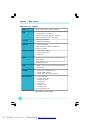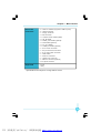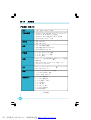
1
Statement: This manual is the intellectual property of Foxconn, Inc. Although the information in this manual may be changed or modified at any time, Foxconn does not obligate itself to inform the user of these changes. Trademark: All trademarks are the property of their respective owners. Version: User’s Manual V1.0 for A6VMX Series motherboard. P/N: 3A220JS00-000-G Symbol description: Note: refers to important information that can help you to use motherboard better. Attention: indicates that it may damage hardware or cause data loss, and tells you how to avoid such problems. Warning: means that a potential risk of property damage or physical injury exists. More information: If you want more information about our products, please visit Foxconn’s website: http://www.foxconnchannel.com WEEE: The use of the symbol indicates that this product may not be treated as household waste. By ensuring this product is disposed of correctly, you will help prevent potential negative consequences for the environment and human health, which could otherwise be caused by inappropriate waste handling of this product. For more detailed information about recycling of this product, please contact your local city office, your household waste disposal service or the shop where you purchased the product. PDF 文件使用 "pdfFactory" 试用版本创建 www.fineprint.com.cn Declaration of conformity HON HAI PRECISION INDUSTRY COMPANY LTD 66 , CHUNG SHAN RD., TU-CHENG INDUSTRIAL DISTRICT, TAIPEI HSIEN, TAIWAN, R.O.C. declares that the product Motherboard A6VMX/A6VMX-S/A6VMX-K is in conformity with (reference to the specification under which conformity is declared in accordance with 89/336 EEC-EMC Directive) þ þ þ þ EN 55022: 1998/A2: 2003 Limits and methods of measurements of radio disturbance characteristics of information technology equipment EN 61000-3-2/:2000 Electromagnetic compatibility (EMC) Part 3: Limits Section 2: Limits for harmonic current emissions (equipment input current <= 16A per phase) EN 61000-3-3/A1:2001 Electromagnetic compatibility (EMC) Part 3: Limits Section 2: Limits of voltage fluctuations and flicker in low-voltage supply systems for equipment with rated current <= 16A EN 55024/A2:2003 Information technology equipment-Immunity characteristics limits and methods of measurement Signature : Printed Name : Place / Date : James Liang Position/ Title : TAIPEI/2007 Assistant President PDF 文件使用 "pdfFactory" 试用版本创建 www.fineprint.com.cn ³³ Declaration of conformity Trade Name: FOXCONN Model Name: A6VMX/A6VMX-S/A6VMX-K Responsible Party: Address: PCE Industry Inc. 458 E. Lambert Rd. Fullerton, CA 92835 Telephone: 714-738-8868 Facsimile: 714-738-8838 Equipment Classification: Type of Product: Manufacturer: FCC Class B Subassembly Motherboard HON HAI PRECISION INDUSTRY COMPANY LTD Address: 66 , CHUNG SHAN RD., TU-CHENG INDUSTRIAL DISTRICT, TAIPEI HSIEN, TAIWAN, R.O.C. Supplementary Information: This device complies with Part 15 of the FCC Rules. Operation is subject to the following two conditions : (1) this device may not cause harmful interference, and (2) this device must accept any interference received, including interference that may cause undesired operation. Tested to comply with FCC standards. Signature : Date : 2007 PDF 文件使用 "pdfFactory" 试用版本创建 www.fineprint.com.cn ³³ Table of Contents Chapter 1 Main Features Specifications............................................................................................ 2 Jumpers ...................................................................................................18 Chapter 2 BIOS Description Enter BIOS Setup ................................................................................. 21 Main menu ............................................................................................ 21 1. Standard CMOS Features .......................................................... 22 2. Central Control Unit .................................................................... 24 3. Advanced BIOS Features ........................................................... 25 4. Advanced Chipset Features....................................................... 26 5. Integrated Peripherals ............................................................... 27 6. Power Management Setup ........................................................ 28 7. PnP/PCI Configuration ............................................................... 29 8. PC Health Status ........................................................................ 30 9. BIOS Security Features .............................................................. 30 10. Load Optimal Defaults ............................................................. 31 11. Save Changes and Exit ............................................................ 31 12. Discard Changes and Exit ....................................................... 31 Chapter 3 Directions for Bundled Software FOX ONE ............................................................................................... 33 FOX LiveUpdate ................................................................................... 36 FOX LOGO ............................................................................................ 38 FOX DMI ................................................................................................ 39 PDF 文件使用 "pdfFactory" 试用版本创建 www.fineprint.com.cn Attention: 1. Attach the CPU and heatsink using silica gel to ensure full contact. 2. It is suggested to select high-quality, certified fans in order to avoid damaging the motherboard and CPU due to high temperature. 3. Never turn on the computer if the CPU fan is not properly installed. 4. Ensure that the DC power supply is turned off before inserting or removing expansion cards or other peripherals, especially when you insert or remove a memory module. Failure to switch off the DC power supply may result in serious damage to your system or memory module. Attention: W e cannot guarantee that your system will operate normally while over-clocked. Normal operation depends on the over-clock capacity of your device. Attention: Since BIOS programs are upgrated from time to time, the BIOS description in this manual is just for reference. W e do not guarantee that the content of this manual will remain consistent with the actual BIOS version at any given time in the future. Attention: The pictures of objects used in this manual are just for your reference. Please refer to the physical motherboard. Attention: Please visit the Foxconn global English website (http://www. foxconnchannel.com) to download the latest BIOS file and drivers for this motherboard. PDF 文件使用 "pdfFactory" 试用版本创建 www.fineprint.com.cn 1 Chapter Thank you for buying Foxconn’s A6VMX Series motherboard. This series of motherboard is one of our new products, and offers superior performance, reliability and quality, at a reasonable price. This motherboard adopts the advanced AMD 690V+SB600 chipset, providing a computer platform with high integration, powerful compatibility and high performance-price ratio for users. This chapter includes the following information: v Specifications v Jumpers PDF 文件使用 "pdfFactory" 试用版本创建 www.fineprint.com.cn ×ÿ× Chapter 1 Main Features Specifications - - English Size ·Micro ATX form factor : 244mm x 208mm CPU · Socket AM2 for AMD AthlonTM 64 X2 ,AthlonTM X2 ,AthlonTM 64 and SempronTM processors · Socket AM2+ for AMD PhenomTM processor ·Supports HyperTransportTM Technology Chipset ·Northbridge: AMD 690V ·Southbridge: AMD SB 600 Memory ·2 x 240-pin DIMM slots ·Supports Dual-Channel DDR2 800/667/533 ·Supports up to 4GB Expansion Slots ·1 x PCI Express x16 slot ·1 x PCI Express x1 slot ·2 x PCI slots Audio ·Realtek 6-channel Audio CODEC / Realtek 8-channel Audio CODEC ·Supports S/PDIF output, Jack-Sensing function, Intel® High Definition Audio LAN ·Realtek 10/100 Mb/s LAN Controller / Realtek Gigabit LAN Controller Storage · 2 x Ultra DMA 133/100/66 devices · 4 xSATA 300MB/s devices · RAID 0, RAID 1, RAID 10 configuration Rear Panel I/O ·1 x PS/2 Mouse Port ·1 x PS/2 Keyboard Port ·1 x Serial Port (COM1) ·1 x Parallel Port ·1 x VGA Port ·4 x USB 2.0 Ports ·1 x RJ45 LAN Port ·6/8-channel Audio Ports (continued on the next page) 2 PDF 文件使用 "pdfFactory" 试用版本创建 www.fineprint.com.cn Chapter 1 Main Features Internal I/O ·2 x USB 2.0 headers (supports 4 USB 2.0 ports) Connectors ·4 x SATA connectors ·1 x Floppy connector ·1 x IDE connector ·1 x Chassis intruder header (INTR) ·1 x CD_IN header ·1 x S/PDIF_OUT header (optional) ·1 x TPM header (optional) ·1 x TV_OUT header ·1 x COM2 port header (optional) ·1 x Front Audio connector ·1 x 24-pin ATX Power Connector ·1 x 4-pin AUX Power Connector ·1 x IrDA header ·1 x CPU Fan connector ·1 x System Fan connector ·1 x NB Fan connector (optional) ·Front panel connector Support CD ·Driver ·Utility ·Specifications are subject to change without notice 3 PDF 文件使用 "pdfFactory" 试用版本创建 www.fineprint.com.cn 第一章 主要性能 产品规格- -简体中文 尺寸 · mATX 结构: 244mm x 208mm 中央处理器 · 支持Socket AM2 规格 AMD AthlonTM 64 X2,AthlonTM X2,AthlonTM 64 和 SempronTM 处理器 · 支持Socket AM2+ 规格 AMD PhenomTM 处理器 · 支持 HyperTransportTM 技术 芯片组 ·北桥:AMD 690V ·南桥:AMD SB 600 内存 ·2 个 240针脚内存插槽 ·支持双通道 DDR2 800/667/533 · 内存总容量最大可达 4GB 扩展槽 ·1 个 PCI Express x16 插槽 ·1 个 PCI Express x1 插槽 ·2 个 PCI 插槽 音频 ·Realtek 6 声道音频编解码器/ Realtek 8 声道音频 编解码器 ·支持 S/PDIF 输出,Jack-Sensing 功能, Intel® High Definition Audio LAN ·Realtek Gigabit LAN Controller/ Realtek 10/100 Mb/s LAN Controller 存储 · 2 个 Ultra DMA 133/100/66设备 · 4 个 SATA 300MB/s 设备 · RAID 0,RAID1,RAID 10 后面板I / O ·1 个 PS/2 鼠标接口 ·1 个 PS/2 键盘接口 ·1 个 串行接口(COM1) ·1 个 并行接口 ·1 个 VGA 接口 ·4 个 USB 2.0 接口 ·1 个 RJ45 网络接口 ·6/8声道音频接口 (下页继续) 4 PDF 文件使用 "pdfFactory" 试用版本创建 www.fineprint.com.cn 第一章 主要性能 内置连接器 ·2 个 USB 2.0 接头(提供 4 USB 2.0 接口) ·4 个 SATA 接头 ·1 个 软驱接口 ·1 个 IDE 接口 ·1 个 机箱开启侦测接头 ·1 个 CD_IN 接头 ·1 个 S/PDIF_OUT 接头(选配) ·1 个 TPM 接头(选配) ·1 个 TV_OUT 接头 ·1 个 COM2 接头(选配) ·1 个 前置音频接头 ·1 个 24 针ATX 电源接口 ·1 个 4 针 AUX 电源接口 ·1 个 红外线通讯接头 ·1 个 CPU 风扇接头 ·1 个 系统风扇接头 ·1 个 北桥风扇接头(选配) ·前端面板接头 实用程序光盘 ·驱动程序 ·应用程序 ·规格若有任何更改,恕不另行通知 5 PDF 文件使用 "pdfFactory" 试用版本创建 www.fineprint.com.cn Kapitel 1 Hauptmerkmale Technische Daten--Deutsch Größe ·Micro ATX-Formfaktor: 244 mm x 208 mm CPU · AM2-Sockel für AMD Athlon™ 64 X2, Athlon™X2, Athlon™ 64 und Sempron™-Prozessoren · AM2+-Sockel für AMD Phenom™-Prozessor ·Unterstützt HyperTransport™-Technologie Chipsatz ·Northbridge: AMD 690V ·Southbridge: AMD SB600 Speicher ·2 240-polige DIMM-Steckplätze · Unterstützt Dual-Channel DDR2 800/667/533 ·Unterstützt bis 4 GB Erweiterungs ·1 x PCI Express x16-Steckplatz steckplätze ·1 x PCI Express x1-Steckplatz ·2 x PCI-Steckplätze Audio ·Realtek 6-Kanal-Audio CODEC/ Realtek 8-Kanal-Audio CODEC ·Unterstützt S/PDIF-Ausgang, Anschlusserkennung, Intel® High Definition Audio LAN ·Realtek Gigabit LAN Controller/ Realtek 10/100 Mb/s LAN Controller Speichergeräte ·2 x Ultra DMA 133/100/66-Geräte ·4 x SATA-Geräte, 300 MB/s · RAID-Konfiguration 0, 1,10 I/O-Anschlüsse ·1 x PS/2-Mausanschluss an der Rückseite ·1 x PS/2-Tastaturanschluss ·1 x Seriellanschluss(COM1) ·1 x Parallelanschluss ·1 x VGA-Port ·4 x USB 2.0-Ports ·1 x RJ45-LAN-Port ·6/8-Kanal-Audio-Port (Fortsetzung auf der nächsten Seite) 6 PDF 文件使用 "pdfFactory" 试用版本创建 www.fineprint.com.cn Kapitel 1 Hauptmerkmale Interne I/OAnschlüsse ·2 x USB 2.0-Anschlussleisten (Unterstützung für 4 USB 2.0-Ports) ·4 x SATA-Anschlüsse ·1 x Diskettenlaufwerkanschluss ·1 x IDE-Anschluss ·1 x Gehäuse-offen-Anschluss (INTR) ·1 x CD_IN-Anschluss ·1 x S/PDIF_OUT-Anschluss(optional) ·1 x TPM-Anschluss(optional) ·1 x TV_OUT-Anschluss ·1 x COM2-Port-Anschluss(optional) ·1 x Front-Audio-Anschluss ·1 x ATX Power, 24-polig-Anschluss ·1 x AUX Power, 4-polig-Anschluss ·1 x IrDA-Anschluss ·1 x CPU-Lüfter-Anschluss ·1 x Systemlüfter-Anschlüsse ·1 x NB- Lعfter (optional) ·Frontbedienfeld-Anschluss Support-CD ·Treibe ·Dienstprogramme ·Angaben können sich ohne Vorankündigung ändern. 7 PDF 文件使用 "pdfFactory" 试用版本创建 www.fineprint.com.cn Capítulo 1 Principales funciones Características- -Español Tamaño ·Micro ATX factor de forma: 244mm x 208mm CPU · Conector AM2 para procesadores AMD AthlonTM 64 X2, AthlonTM X2, AthlonTM 64 y SempronTM ·Conector AM2+ para procesador AMD PhenomTM ·Compatible con HyperTransportTM Conjunto de chips ·Northbridge: AMD 690V ·Southbridge: AMD SB 600 Memoria ·2 x ranuras DIMM de 240-pin ·Compatible DDR 2 de doble canal 800/667/533 ·Compatible con hasta 4GB Ranuras ·1 x ranuras PCI Express x16 de expansión ·1 x ranura PCI Express x1 ·2 x ranuras PCI Audio ·Realtek 6 canales Audio CODEC / Realtek 8 canales Audio CODEC ·Compatible salida S/PDIF, sensible a conexión, sonido Intel® de Alta Definición LAN ·Realtek Gigabit LAN Controller / Realtek 10/100 Mb/s LAN Controller Almacenamiento ·2 X dispositivos Ultra DMA 133/100/66 ·Dispositivo 4 SATA 300MB/s ·Configuración RAID 0, RAID 1, RAID 10 Panel de E/S ·1 x Puerto de ratón PS/2 trasero ·1 x Puerto de teclado PS/2 ·1 x Puerto Serie(COM1) ·1 x Puerto Paralelo ·1 x Puerto de VGA ·4 x Puertos USB 2.0 ·1 x Puerto LAN RJ45 ·Puerto de 6/8 canales Audio (continúa en la página siguiente) 8 PDF 文件使用 "pdfFactory" 试用版本创建 www.fineprint.com.cn Capítulo 1 Principales funciones Conectores ·2 x Cabeceras USB 2.0 (admite 4 puertos USB 2.0) internos de E/S ·4 x Conectores SATA ·1 x Conector de disco flexible ·1 x Conector de IDE ·1 x Cabecera de intrusos en bastidor (INTR) ·1 x Cabecera de CD_IN ·1 x Cabecera S/PDIF_OUT(opcional) ·1 x Cabecera TPM (opcional) ·1 x Cabecera TV_OUT ·1 x Conector de puerto COM2 (opcional) ·1 x Conector de Audio frontal ·1 x Conector de 24-pin ATX Power ·1 x Conector de 4-pin AUX Power ·1 x Cabecera de IrDA ·1 x Cabecera de Ventilador de CPU ·1 x Conectora de Ventiladores Sistema ·1 x Ventilador NB(opcional) ·Conector de panel frontal CD de soporte ·Controlador ·Utilidades ·Las características se encuentran sujetas a cambios sin aviso previo. 9 PDF 文件使用 "pdfFactory" 试用版本创建 www.fineprint.com.cn Capítulo 1 Principais características Especificações- -Portugués Tamanho ·Factor de forma Micro ATX de 244 x 208 mm CPU · Socket AM2 para processadores AMD AthlonTM 64 X2, AthlonTM X2, AthlonTM 64 e SempronTM ·Socket AM2+ para processador AMD PhenomTM ·Suporta a tecnologia HyperTransportTM Chipset ·Northbridge: AMD 690V Memória ·2 ranhuras DIMM de 240 pinos ·Southbridge: AMD SB 600 ·Suporta módulos de memória DDR2 800/667/533 de canal duplo ·Suporta até 4 GB Ranhuras de ·1 ranhura PCI Express x16 expansão ·1 ranhura PCI Express x1 ·2 ranhuras PCI Áudio ·Realtek com 6 canais, codec de áudio / Realtek 8 canais, codec de áudio ·Suporta saída S/PDIF, função Jack-Sensing, áudio de alta definição da Intel® LAN ·Realtek Gigabit LAN Controller / Realtek 10/100 Mb/s LAN Controller Armazenamento ·2 dispositivos Ultra DMA 133/100/66 ·4 dispositivos SATA de 300 MB/s ·Configuração RAID 0, RAID1, RAID10 Entrada/Saída ·1 x Porta para rato PS/2 pelo painel ·1 x Porta para Teclado PS/2 traseiro ·1 x Porta série (COM1) ·1 x Porta paralela ·1 x Porta VGA ·4 x Portas USB 2.0 ·1 x Porta LAN RJ45 ·Porta 6/8 canais, áudio (continua na página seguinte) 10 PDF 文件使用 "pdfFactory" 试用版本创建 www.fineprint.com.cn Capítulo 1 Principais características Conectores ·2 x Conectores USB 2.0 (para 4 portas USB 2.0) internos de ·4 x Conectores SATA entrada/saída ·1 x Conector da unidade de disquetes ·1 x Conector IDE ·1 x Conector para detecção de intrusão no chassis(INTR) ·1 x Conector CD_IN ·1 x Conector S/PDIF_OUT (opcional) ·1 x Conector TPM (opcional) ·1 x Conector TV_OUT (opcional) ·1 x Conector da porta COM2 (opcional) ·1 x Conector Áudio frontal ·1 x Conector de alimentação ATX de 24 pinos ·1 x Conector de alimentação auxiliar de 4 pinos ·1 x Conector IrDA ·1 x Conector da ventoinha da CPU ·1 x Conector ventoinha do sistema ·1 x Ventoinha NB(opcional) ·Conector de painel frontal CD de suporte ·Controlador ·Utilitários ·As especificações estão sujeitas a alteração sem aviso prévio. 11 PDF 文件使用 "pdfFactory" 试用版本创建 www.fineprint.com.cn Capitolo 1 Caratteristiche principali Specifiche- -Italiano Dimensioni CPU ·Formato micro ATX: 244 mm x 208 mm · Socket AM2 per processori AMD AthlonTM 64 X2, AthlonTM X2, AthlonTM 64 e SempronTM · Socket AM2+ per processor AMD PhenomTM · Supporto tecnologia HyperTransportTM Chipset ·Northbridge: AMD 690V Memoria ·2 alloggi DIMM 240 pin ·Southbridge: AMD SB600 ·Supporto DDR2 800/667/533 Dual-Channel ·Supporto fino a 4GB Alloggi ·1 Alloggio PCI Express x16 d’espansione ·1 Alloggio PCI Express ·2 Alloggi PCI Audio ·Realtek 6-canali audio CODEC / Realtek 8-canali audio CODEC ·Supporto output S/PDIF, funzione di rilevamento connettori, Intel® High Definition Audio LAN ·Realtek Gigabit LAN Controller / Realtek 10/100 Mb/s LAN Controller Archivio ·2 Dispositivi Ultra DMA 133/100/66 ·4 dispositivi SATA 300MB/s ·Configurazione RAID 0, RAID1,RAID10 Pannello posteriore I/O ·1 x Porta mouse PS/2 ·1 x Porta tastiera PS/2 ·1 x Porta Seriale (COM1) ·1 x Porta Parallela ·1 x Porta VGA ·4 x Porta USB 2.0 ·1 x Porta LAN RJ45 ·Porta 6/8-canali audio (segue alla pagina successiva) 12 PDF 文件使用 "pdfFactory" 试用版本创建 www.fineprint.com.cn Capitolo 1 Caratteristiche principali Connettori I/O ·2 x Collettori USB 2.0 (supportano 4 porte USB 2.0) interni ·4 x Connettori SATA ·1 x Connettore Floppy ·1 x Connettore IDE ·1 x Collettore intrusione telaio (INTR) ·1 x Collettore CD_IN ·1 x Collettore S/PDIF_OUT (optional) ·1 x CollettoreTPM (optional) ·1 x Collettore TV_OUT ·1 x Collettore porta COM2 (optional) ·1 x Connettore Audio frontale ·1 x Connettore potenza ATX 24 pin ·1 x Connettore potenza AUX 4 pin ·1 x Connettore IrDA ·1 x Connettore ventolina CPU ·1 x Connettore ventolina di sistema ·1 x Ventolina NB (optional) ·Connettore pannello frontale CD di supporto ·Driver ·Utilità ·Le specifiche tecniche sono soggette a cambiamenti senza preavviso. 13 PDF 文件使用 "pdfFactory" 试用版本创建 www.fineprint.com.cn Глава 1 Основные характеристики Технические характеристики- -Русский Размер Процессор ·Форм-фактор микро-ATX размером 244 х 208 мм · Гнездо AM2 для процессоров AMD AthlonTM 64 X2, AthlonTM X2, AthlonTM 64 и SempronTM · Гнездо AM2+ для процессор AMD PhenomTM · Поддержка технологии HyperTransportTM Набор микросхем ·Северный мост: AMD 690V ·Южный мост: AMD SB 600 Память ·2 240-контактных гнезда DIMM ·Поддержка Двухканальная память DDR2 800, 667, 533 ·Поддержка до 4 Гб Слоты ·Один слот PCI Express x16 расширения ·Один слот PCI Express x1 ·2 слота PCI Звук ·Realtek 6 каналов, звуковой КОДЕК / Realtek 8 каналов, звуковой КОДЕК ·Поддержка Выход S/PDIF, функция определения разъема, поддержка технологии Intel® High Definition Audio ЛВС ·Realtek Gigabit ЛВС / Realtek ЛВС10/100 Мбит/с Устройство ·2 устройств с интерфейсом Ultra DMA 133, 100, 66 хранения ·4 устройств с интерфейсом SATA и скоростью передачи данных 300 Мб/с ·Конфигурации RAID 0,RAID 1, RAID10 Входы и ·1 Порт мыши PS/2 выходы на ·1 Порт Клавиатура PS/2 задней панели ·1 Последовательный порт (COM1) ·1 Параллельный порт ·1 Порт VGA ·4 Порты USB 2.0 ·1 Разъем ЛВС RJ45 ·Порт 6, 8 каналов, звуковой (продолжение на следующей странице) 14 PDF 文件使用 "pdfFactory" 试用版本创建 www.fineprint.com.cn Глава 1 Основные характеристики Встроенные ·2 Разъемы USB 2.0 (поддержка 4 портов USB 2.0) входы и ·4 Разъемы SATA выходы ·1 Разъем дисковода гибких дисков ·1 Разъем IDE ·1 Разъем датчика открывания корпуса (INTR) ·1 Разъем CD_IN ·1 Разъем S/PDIF_OUT (дополнительный) ·1 Разъем TPM (дополнительный) ·1 Разъем ТВ-выход ·1 Разъем порт COM2 (дополнительный) ·1 Передний звуковой разъем ·1 Разъем 24-контактный ATX ·1 Разъем 4-контактый AUX ·1 ИК-порт ·1 Разъем Вентилятор процессора ·1 Разъемы системный вентилятор ·1 Вентилятор северного моста (дополнительный) ·Передняя панель разъем Поддержка ·Драйвер компакт-дисков ·Служебная программа ·Технические характеристики могут изменяться без уведомления. 15 PDF 文件使用 "pdfFactory" 试用版本创建 www.fineprint.com.cn اﻟﻔﺼﻞ 1اﻟﺨﺼﺎﺋﺺ اﻟﺮﺋﯿﺴﯿﺔ اﻟﻤﻮاﺻﻔﺎت- -ﻟﻌﺮﺑﯿ ﺔ اﻟﺤﺠﻢ وﺣﺪة اﻟﻤﻌﺎﻟﺠﺔ اﻟﻤﺮﻛﺰﯾﺔ Ÿﺣﺎوﯾﺔ ﻣﻦ ﻧﻮع Micro ATXﻣﻘﺎس 24 4ﻣﻢ × 208ﻣﻢ Ÿﻣﻘﺒﺲ AM2ﻟﻤﻌﺎﻟﺠﺎت AMD At hlonTM64X2و AthlonTMX2 وAthlonTM 64 and SempronTM Ÿﻣﻘﺒﺲ AM2 +ﻟﻤﻌﺎﻟﺠﺎت AMD PhenomTM Ÿدﻋﻢ ﺗﻘﻨﯿﺔ HyperTransportTM اﻟﺮﻗﺎﺋﻖ Ÿاﻟﺠﺴﺮ اﻟﺸﻤﺎﻟﻲ )AMD 690V :(Northbridge Ÿاﻟﺠﺴﺮ اﻟﺠﻨﻮﺑﻲ )AMD SB 600 :(Southbridge اﻟﺬاﻛﺮة Ÿﻋﺪد 2ﻓﺘﺤﺎت 240 × DIMMدﺑﻮﺳﺎ Ÿدﻋﻢ اﻟﺘﺼﻤﯿﻢ ﺛﻨﺎﺋﻲ اﻟﻘﻨﺎة Dual-Channel DDR2 800/667/533 Ÿدﻋﻢ ﯾﺼﻞ إﻟﻰ 4ﺟﯿﺠﺎ ﺑﺎﯾﺖ ﻓﺘﺤﺎت اﻟﺘﻮﺳﻌﺔ Ÿﻋﺪد 1ﻓﺘﺤﺔ PCI Express x16 Ÿﻋﺪد 1ﻓﺘﺤﺔ PCI Express x1 Ÿﻋﺪد 2ﻓﺘﺤﺎت PCI اﻟﺼﻮت Ÿﺗﺮﻣﯿﺰ ﺻﻮﺗﻲ ﺑﺴﺖ ﻗﻨﻮات ﺑﺘﻘﻨﯿﺔ/Realtekﺗﺮﻣﯿﺰ ﺻﻮﺗﻲﺑﺜﻤﺎنﻗﻨﻮات ﺑﺘﻘﻨﯿﺔ Realtek Ÿدﻋﻢ ﺧﺮج ،S/PDIFوﻇﯿﻔﺔ اﺳﺘﺸﻌﺎر اﻟﻤﻘﺒﺲ ،ﺗﻘﻨﯿﺔ Intel® High Definition Audio ﺷﺒﻜﺔ اﻻﺗﺼﺎل اﻟﻤﺤﻠﯿﺔ Realtek 10/100 Mb/s LAN Controller / Realtek Gigabit LAN l Controller اﻟﺘﺨﺰﯾﻦ Ÿﻋﺪد 2أﺟﮭﺰة Ultra DMA 133/ 100/66 Ÿﻋﺪد 4أﺟﮭﺰة SATA 300MB/s Ÿﺗﮭﯿﺌﺔ RAID 0, RAID 1, RAID 10 ﻣﻨﺎﻓﺬ اﻟﺪﺧﻞ/اﻟﺨﺮج ﻟﻠﻮﺣﺔ اﻟﺨﻠﻔﯿﺔ Ÿﻋﺪد 1ﻣﻨﻔﺬ ﻣﺎوس PS/2 Ÿﻋﺪد 1ﻣﻨﻔﺬ ﻟﻮﺣﺔ ﻣﻔﺎﺗﯿﺢ PS/2 Ÿﻋﺪد 1ﻣﻨﻔﺬ ﺗﺴﻠﺴﻠﻲ )(COM1 Ÿﻋﺪد 1ﻣﻨﻔﺬ ﻣﺘﻮازي Ÿﻋﺪد 1ﻣﻨﻔﺬ VGA Ÿﻋﺪد 4ﻣﻨﺎﻓﺬ USB 2.0 Ÿﻋﺪد 1ﻣﻨﻔﺬ ﺷﺒﻜﺔ اﺗﺼﺎل ﻣﺤﻠﯿﺔ RJ45 Ÿﻣﻨﺎﻓﺬ ﺻﻮﺗﻲ ﺑﺴﺖ /ﺑﺜﻤﺎن ﻗﻨﻮات ﺑﺘﻘﻨﯿﺔ ﺗﺎﺑﻊ اﻟﺼﻔﺤﺔ اﻟﺘﺎﻟﯿﺔ 16 PDF 文件使用 "pdfFactory" 试用版本创建 www.fineprint.com.cn اﻟﻔﺼﻞ 1اﻟﺨﺼﺎﺋﺺ اﻟﺮﺋﯿﺴﯿﺔ ﻣﻨﺎﻓﺬ ﺗﻮﺻﯿﻞ اﻟﺪﺧﻞ /اﻟﺨﺮج Ÿﻋﺪد 2أﻃﺮاف ﺗﻮﺻﯿﻞ ) USB 2.0ﺗﺪﻋﻢ 4ﻣﻨﺎﻓﺬ (USB 2.0 اﻟﺪاﺧﻠﯿﺔ Ÿﻋﺪد 4ﻣﻨﺎﻓﺬ ﺗﻮﺻﯿﻞSATA Ÿﻋﺪد 1ﻣﻨﻔﺬ ﺗﻮﺻﯿﻞ ﻣﺤﺮك اﻷﻗﺮاص اﻟﻤﺮﻧﺔ Ÿﻋﺪد 1ﻣﻨﻔﺬ ﺗﻮﺻﯿﻞIDE Ÿﻋﺪد 1ﻃﺮف ﺗﻮﺻﯿﻞ Intruderﻟﻠﮭﯿﻜﻞ ) (INTR Ÿﻋﺪد 1ﻃﺮف ﺗﻮﺻﯿﻞ CD_IN Ÿﻋﺪد 1ﻃﺮف ﺗﻮﺻﯿﻞ) S/PDI F _OUTاﺧﺘﯿﺎري( Ÿﻋﺪد 1ﻃﺮف ﺗﻮﺻﯿﻞ) TPMاﺧﺘﯿﺎري( Ÿﻋﺪد 1ﻃﺮف ﺗﻮﺻﯿﻞ ﺧﺮج اﻟﺘﻠﻔﺰﯾﻮن TV_OUT Ÿﻋﺪد 1ﻃﺮف ﺗﻮﺻﯿﻞ ) COM2اﺧﺘﯿﺎري( Ÿﻣﻮﺻﻞ اﻟﺼﻮت اﻷﻣﺎﻣﻲ Ÿﻋﺪد 1ﻣﻮﺻﻞ ﻃﺎﻗﺔ، ATXء 24دﺑﻮس Ÿﻋﺪد 1ﻣﻮﺻﻞ ﻃﺎﻗﺔ 4 × AUXدﺑﺎﺑﯿﺲ Ÿﻋﺪد 1ﻃﺮف ﺗﻮﺻﯿﻞ IrDA Ÿﻋﺪد 1ﻣﺮوﺣﺔ ﻟﻮﺣﺪة اﻟﻤﻌﺎﻟﺠﺔ اﻟﻤﺮﻛﺰﯾﺔ ﻣﻮﺻﻞ ﻟﻤﺮوﺣﺔ اﻟﻨﻈﺎم Ÿﻋﺪد 1 Ÿﻋﺪد NB1ﻣﺮوﺣﺔ )اﺧﺘﯿﺎري( Ÿﻣﻮﺻﻞ اﻟﻠﻮﺣﺔ اﻷﻣﺎﻣﯿﺔ دﻋﻢ اﻟﻘﺮص اﻟﻤﺪم Ÿﺑﺮﻧﺎﻣﺞ اﻟﺘﺸﻐﯿﻞ Ÿاﻷدوات Ÿﻗﺪ ﺗﺘﻐﯿﺮ اﻟﻤﻮاﺻﻔﺎت ﺑﺪون إﺧﻄﺎر ﻣﺴﺒﻖ. 17 PDF 文件使用 "pdfFactory" 试用版本创建 www.fineprint.com.cn Chapter 1 Main Features Jumpers This section explains how to setup jumpers. You should read the following content carefully prior to modifying any jumper settings. Attention The jumpers on the motherboard, pin 1 can be identified by the bold silkscreen next to it. And in this manual, pin 1 is simply labeled as “1”. Clear CMOS Jumper: CLR_CMOS The CLR_CMOS jumper allows you to clear the data in CMOS. The data includes system setup information such as system password, data, time, and system setup parameters. To clear and reset the system parameters to default setup, please do as follows: 1. Turn off the computer and unplug the power cord from the power supply. 2. Move the jumper cap from pins 2-3 (default) to pins 1-2. Keep the cap on pins 1-2 for several seconds, then move the cap back to pins 2-3. 3. Plug the power cord and turn on the computer. Normal 1 (default) 1 Clear CLR_ CMOS USB device wake-up Jumper: USBPWR1/USBPWR2 1.Set the jumper to pins 1-2 (+5V) to wake up the computer from S1 sleep mode using the connected USB devices. 2.Set the jumper to pins 2-3 (+5VSB) to wake up the computer from S3 and S4 sleep modes using the connected USB devices. At the same time, a corresponding setting must be set in BIOS as below: Set “CMOS Setup”=>“Power Management Setup”=> “Wake on USB Devices” to “Enabled”. 1 +5VSB +5V 1 (Default) USBPWR1 / USBPWR2 Note 1. USBPW R1 is for the rear USB connectors, USBPW R2 is for the internal USB ports. 2. The USB device wake-up feature requires a power supply that can provide 500mA on +5VSB lead for each USB port; otherwise, the system will not power up. 3. The total current consumed must not exceed the power supply capability (+5VSB) whether under normal condition or in sleep mode. 18 PDF 文件使用 "pdfFactory" 试用版本创建 www.fineprint.com.cn ³³ Chapter 1 Main Features Keyboard and Mouse Jumper: KB/MS_PWR This jumper allows you to enable or disable the Key- +5V board and Mouse wake-up feature. Set the jumper to (Default) pins 2-3(+5VSB) to wake up the computer from sleep modes when you press a key on the keyboard or click the mouse, and a corresponding setting must be set in BIOS as below: Set “CMOS Setup”=>“Power Management Setup”=> “Wake on PS2 Keyboard”and “W ake on PS2Mouse” to “Enabled”. 1 1 +5VSB KB/MSPWR 19 PDF 文件使用 "pdfFactory" 试用版本创建 www.fineprint.com.cn Chapter 2 BIOS Description 2 Chapter This chapter introduces how to change system settings through the BIOS Setup menus. You have to run the Setup Program when the following cases occur: 1. An error message appears on the screen during the system POST process. 2. You want to change the default CMOS settings. This chapter includes the following information: v Enter BIOS Setup Main Menu v v Standard CMOS Features v Central Control Unit v Advanced BIOS Features v Advanced Chipset Features v Integrated Peripherals v Power Management Setup v PnP/PCI Configuration v PC Health Status v BIOS Security Features v Load Optimal Defaults v Save Changes and Exit v Discard Changes and Exit 20 PDF 文件使用 "pdfFactory" 试用版本创建 www.fineprint.com.cn ×ÿ× Chapter 2 BIOS Description Enter BIOS Setup The BIOS is the communication bridge between hardware and software. Correctly setting up the BIOS parameters is critical to maintain optimal system performance. Power on the computer, when the following message briefly appears at the bottom of the screen during the POST (Power On Self Test), press <Del> key to enter the BIOS CMOS Setup Utility. Press TAB to show POST Screen, DEL to enter SETUP. Note: W e do not suggest that you change the default parameters in the BIOS Setup, and we shall not be responsible for any damage that results from any changes that you make. Main Menu The main menu displays a list of options that are available. Use the arrow keys to highlight an item, and execute the item by pressing <Enter>. Main Menu The items in the main menu are explained as below: 1. Standard CMOS Features The basic system configuration can be set up through this menu. 2. Central Control Unit The special features can be set up by this menu. 3. Advanced BIOS Features The advanced system features can be set up through this menu. 4. Advanced Chipset Features The advanced chipset features can be set up through this menu. 5. Integrated Peripherals All onboard peripherals can be set up through this menu. 21 PDF 文件使用 "pdfFactory" 试用版本创建 www.fineprint.com.cn ³³ Chapter 2 BIOS Description 6. Power Management Setup Through this menu you can set up all the Power Management events related items. 7. PnP/PCI Configuration The system’s PnP/PCI settings and parameters can be modified by this menu. 8.PC Health Status This menu will display the current status of your PC. 9. BIOS Security Features BIOS Secutiry configuration can be setted through this item. 10. Load Optimal Defaults You can load the optimal performance settings by this menu; however, the stable default values may be affected. 11. Save Changes and Exit Save CMOS value settings to CMOS and exit setup. 12. Discard Changes and Exit Abandon all CMOS value changes and exit setup. 1.Standard BIOS Features This sub-menu is used to set up the standard BIOS parameters, such as the date, time, floppy driver and so on. Select the item by the arrow keys, and then use the <+> or <-> keys to choose the setting values. Standard BIOS Features Menu 1.1 AMIBIOS This item shows the version and build date of the AMIBIOS. 1.2 System Time/Date This item allows you to set up the desired time and date(usually as the current time and date) with <hour><minute><second><day><month> <date><year> format. 22 PDF 文件使用 "pdfFactory" 试用版本创建 www.fineprint.com.cn ÆÆ Chapter 2 BIOS Description Day—weekday from Sun. to Sat. Month—month from 1 to 12 Date—date from 1 st to 31 st Year—year, set up by users. Use <ENTER>,<TAB> or <SHIFT+TAB>to select a field.Use <+>or <-> to configure system time and date. 1.3 IDE Configuration You may set configurations for the IDE device that you specify through this item. Take “Primary IDE Master” for example, when you set “Type” to “Auto”, please pay attention to the bellow warning. Warning: After selecting the hard disk information into BIOS, use a disk utility, such as FDISK,to partition or format the new IDE hard disk drives. This is necessary so that you can write or read data from the disk. Make sure to set the partition of the Primary IDE hard disk drives to active. 1.4 Floppy A This option allows you to select the kind of FDD installed, including [none], [360K, 51/4 in], [1.2M, 51/4in], [720K, 31/2 in], [1.44M, 31/2 in] and [2.88 M, 31/2 in]. 1.5 System Memory This item shows the system memory size. 1.6 Halt On This category determines whether or not the computer will stop if an error is detected during powering up. All Errors Whenever the BIOS detects a nonfatal error, the system will stop and you will be prompted. All Errors But ...... All errors except keyboard,mouse and floppy can result in system halt on. This requires you to set “Keyboard”, “Mouse” and “Floppy” as “Enabled”. 1.7 Keyboard/Mouse/Floppy This item allows system to detect if the Keyboard/ Mouse/ Floppy is available automatically when booting.W hen set them to “Enabled”, BIOS will skip the detection of the keybord, Mouse and Floppy.W hen set to “Disabled”,BIOS will detect them. 23 PDF 文件使用 "pdfFactory" 试用版本创建 www.fineprint.com.cn Chapter 2 BIOS Description 2. Central Control Unit Central control Unit Menu 2.1 Clock Generator Settings Press “Enter” to set AMD overclocking Configuration. 2.2 Current CPU Speed This item shows the current CPU speed automatically.It can’t be changed manually. 2.3 Current FSB Multiplier This item shows the current speed of the front side bus automatically. 2.4 Maximum FSB Multiplier This item tells you the maximum speed of the front side bus. 2.5 Current Memory Clock This item shows the current memory clock frequency automatically. 2.6 FOXCONN Feature Press “Enter” to set the characteristic features of FOXCONN. 2.1 Clock Generator Settings Clock Generator Settings Menu 2.1.1 CPU Frequency Multiplier You can select the CPU Frequency multiplier through this menu.The frequency 24 PDF 文件使用 "pdfFactory" 试用版本创建 www.fineprint.com.cn ÆÆ Chapter 2 BIOS Description is The default value is “Auto”.If your CPU does not support frequency change. This item will be grayed-out. 2.1.2 CPU/HT Reference Clock (MHz) Use this item to set the CPU /Hypertransport frequency. 2.1.3 PCIE Graphics Clock (MHz) This item allows you to set the frequency of PCIE Graphics card. The default value is 100. 2.1.4 Spread Spectrum Use this item to enable or disable the spread spectrum functions. NOTE: The Spread Spectrum function can influence the EMI (Electromagnetic Interference)degree. 2.6 FOXCONN Feature FOXCONN Feature Menu 2.6.1 CPU Voltage Control Use this item to adjust the CPU core voltage manually. The voltage range is +25mv~+800mv. “Disabled” is the default value. 2.6.2 DIMM Voltage Control You are able to use this item to select the DIMM voltage.The voltage range is +25mv~+600mv. “Disabled” is the default value. 2.6.3 NB Voltage Control Through this item, you may adjust the North Bridge volatge manually. 2.6.4 Smart Power LED Smart debug LED function within power LED. Enable this function, the power LED status can show the system status of POST process. If it detect the memory or graphics cards fail , the power LED will blink. 3.Advanced BIOS Features 25 PDF 文件使用 "pdfFactory" 试用版本创建 www.fineprint.com.cn ÆÆ Chapter 2 BIOS Description Advanced BIOS Features Menu 3.1 CPU Configuration Press “Enter”, you will see the CPU-related information that the BIOS automatically detects. 3.2 Boot Settings Configuration Press “Enter”, you are able to specify the boot device priority sequence from the availabe devices. 3.3 Quick Boot This item allows you to enable or disable the system quick boot feature.W hen enabled, the system skips certain tests while booting. 3.4 Quiet Boot This item is used to enable or disable the quiet boot. [Disabled]: Displays normal POST messages.[Enabled]: Displays OEM Logo instead of POST messages. 3.5 Floppy Drive Seek You may enable or disable the floppy drive seek function through this item. Setting to “Enabled”,the BIOS will search for floppy disk drive at boot time. 3.6 Bootup Num-Lock Use this item to select the power-on state for the Numlock.the default value is “ON” 4.Advanced Chipset Features Advanced Chipset Features Menu 26 PDF 文件使用 "pdfFactory" 试用版本创建 www.fineprint.com.cn ÆÆ Chapter 2 BIOS Description 4.1 AMD 690G/690V Configuration This sub-menu allows you to configure the parameters of Internal Grapgics and PCI Express. 4.2 NorthBridge Configuration This sub-menu allows you to set the memory configuration and enable or disable the power down function. 5.Integrated Peripherals Integrated Peripherals Menu 5.1OnChip SATA Channel This item allows you to enable or disable SATA channel. 5.2 OnChip SATA Type Use this item to select onboard SATA type. Selecting “Native IDE”,the system will only support SATA devices. Selecting “Legance IDE”,the system will support SATA and IDE devices.The default value is “Native IDE”. 5.3 OnBoard Devices This sub-menu allows you to enable or disbale the onbaord devices,such as onboard LAN,USB and Audio. 5.4 SuperIO Configuration This sub-menu allows you to configure superIO devices,such as serial ports , parallel ports and so on.You can configure the resource and operation mode for these devices. 27 PDF 文件使用 "pdfFactory" 试用版本创建 www.fineprint.com.cn ÆÆ Chapter 2 BIOS Description 6.Power Management Setup Power Management Setup Menu 6.1Cool ‘N’ Quiet Enable or disable AMD “Cool ‘N’ Quiet” technology. Cool’N’Quiet is a CPU speed throttling and power saving technology introduced by AMD with their Athlon 64 processor line. It works by reducing the processor’s clock rate and voltage when the computer has low usage. The aim of this technology is to reduce overall power consumption and lower heat generation 6.2 Suspend mode Use this item to define your system suspends. In the default “S3(STR)”,the data and system operation status information will be stored in the memory, and the system will shut down with the exception of a refresh current to the system memory.If you select “S1(POS)”, the CPU clock will stop, but other devices of system still have power supply. 6.3 Power Button Mode This item allows the system go into On/Off mode or suspend mode when the power button is pressed.Options:[On/Off] [Suspend]. 6.4 POWER STATE Use this item to control whether to start up your computer automatically or not after a power failure event.If you selected “Power On”,the computer will automatically start up when restore the power supply.If you selected “Power Off”, the computer will still remain power off. If you selected “Last State”,the computer will resume to the former state. 6.5 Wake on PME This item helps to set whether to wake up the system by power management events or not. 6.6 Wake on USB Devices/PS2 Keyboard/PS2 Mouse Use these items to enable or disable USB Devices/PS2 Keyboard/PS2 Mouse wake-uping function from sleep mode. 28 PDF 文件使用 "pdfFactory" 试用版本创建 www.fineprint.com.cn ÆÆ Chapter 2 BIOS Description 6.7 RTC Resume This item allows you to resume system by RTC alarm. 7.PnP/PCI Configuration PnP/PCI Configuration Menu 7.1Clear NVRAM This item allows you to clear NVRAM(Non Volatile Random Access Memory) during System boot. 7.2 Plug & Play O/S When set to “NO”,the BIOS will configure all devices in the system.When set to “Yes” and if you install a Plug and Play operating system, the operating system configures the Plug and Play devices not required for boot. 7.3 PCI Latency Timer This item allows you to select the value of PCI clocks for the PCI device latency timer register.The default value is 64. 7.4 Allocate IRQ to PCI VGA Select “Yes”, BIOS assigns an IRQ to PCI VGA card,if the card requests. If you select “No”, BIOS does not assign an IRQ to PCI VGA card even if it requested. 7.5 Palette Snooping Set this item to “Enabled”, the palette snooping feature informs the PCI devices that an ISA guaphics device is installed in the system so that the latter can function correctly. 7.6 PCI IDE BusMaster Use this item to enable or disable the PCI IDE BusMaster feature. 7.7 OffBoard PCI/ISA IDE Card Use this item to select PCI slots for the offboard PCI/ISA IDE card to plug in. Set to“Auto”,BIOS will detect a slot for the card automatically.You may also select the PCI slot by yourself. 7.8 IRQ 3/4/5/7/9/10/11/14/15 This item allows to specify IRQ for PCI/PnP devices to use. The default value is”Available”. 29 PDF 文件使用 "pdfFactory" 试用版本创建 www.fineprint.com.cn ÆÆ Chapter 2 BIOS Description 7.9 DMA Channel 0/1/3/5/6/7 Use this item to specify DMA Channel for PCI/PnP devices to use. The default value is“Available”. 7.10 Reserved Memory Size This item allows to reserve size of memory block for legacy ISA deices.W e advise to keep the default value unchanged.The default value is “Disabled”. 8.PC Health Status PC Health Status Menu 8.1 CASE OPEN FUNC This item allows you to enable or disable the chassis open status feature. 8.2 CPU Temperature /System Temperature/CPU Fan Speed/System Fan Speed/+CPU/DDR(+1.8V)/VCC(+5V)/+12V/+3.3V These items display the current CPU/system temperature,fan speed and voltages that are automatically detected by the system. 8.3 CPU/System Smart FAN Function Thease items enable or disable the smart fan function.W hen they are setted at certian temperature.The speed of the fan will increase with the rise of the temperature. 9.BIOS Security Features 30 BIOS Security Features Menu PDF 文件使用 "pdfFactory" 试用版本创建 www.fineprint.com.cn ÆÆ Chapter 2 BIOS Description 9.1 Supervisor/User Password These items show supervisor/user password installed or not. 9.2 BIOS Write Protection Enable this item to protect system BIOS from viruses. 9.3 Change Supervisor Password Press “Enter” to change the supervisor password. The access rights and permissions associated with the Supervisor password are higher than those of a regular User password. The Supervisor password can be used to start the system or modify the CMOS settings.Enter your password, not exceeding 6 characters, then press <Enter>. The password you entered will replace any previous password.If you do not want to set a password, just press <Enter> when prompted to enter a password. 9.4 Boot Sector Virus Protection This item allows to protect boot sector of hard disk from viruses. The default value is “Disabled”. 10.Load Optimal Defaults This menu can let you load the optimal defaults set by BIOS, which have set the optimized performance parameters of system to improve the performances of system components.You can select <OK> or <Cancel> and then press <Enter> to load or not load the optimized defaults. 11.Save Changes and Exit W hen you select this option and press <Enter>, the following message will appear in the center of the screen: Save configuration changes and exit setup? Press <Yes> to save your changes in CMOS and exit the program; press <Cancel> or <ESC> to return to the main menu. 12.Discard Changes and Exit If you select this option and press <Enter>, the following message will appear in the center of the screen: Discard Changes and Exit setup? Press <OK> to exit CMOS without saving your modifications; press <Cancel> or <ESC> to return to the main menu. 31 PDF 文件使用 "pdfFactory" 试用版本创建 www.fineprint.com.cn ÆÆ Chapter 4 Chapter Driver CD Introduction 3 This chapter will introduce how to use attached software. This chapter provides the following information: v FOX ONE v FOX LiveUpdate v FOX LOGO v FOX DMI 32 PDF 文件使用 "pdfFactory" 试用版本创建 www.fineprint.com.cn ×ÿ× Chapter 3 Directions for Bundled Software FOX ONE FOX ONE is a powerful utility for easily modifying system settings. It also allows users to monitor various temperature values, voltage values, frequency and fan speed at any time. With FOX ONE, you can modify system performance settings such as bus speed, CPU voltage, fan speed, and other system performance options that are supported by the BIOS and you also can monitor hardware temperature, voltage, frequency and fan speed. Supported Operating Systems: -W indows 2000 -Windows XP (32-bit and 64-bit) -W indows 2003 (32-bit and 64-bit) -W indows Vista (32-bit and 64-bit) Using FOX ONE: 1. Main Page Show CPU Information Use the toolbar to navigate to other pages Alert Lamp Switch Button Skin Button Exit Minimum Configuration Homepage Monitor Frequency/Voltage/Fan speed/Temperature value Alert Lamp When the system is in healthy status, the alert lamp color is green. And if the system is in abnormal status, the alert lamp color will turn red. Switch Button Click this button, it will simplify the interface to HW monitor information bar as the below figure shows. The bar could help you to monitor if your system is in the healthy status at any time. 33 PDF 文件使用 "pdfFactory" 试用版本创建 www.fineprint.com.cn ÿÿ Chapter 3 Directions for Bundled Software Click here to return to previous status Skin Button Click this button, you will see the additive figures such as “crystal”and “rock”. Please select your favorite skin. Exit Click this button to exit the program. Minimum Click this button to minimize the window. Configuration This function is used to configurate the parameters for the program. It determines which items will be shown in simple mode.Besides,it also provides F.I.S calibration function which will re-calibrate the CPU’s loading. F.I.S calibration function is optional. Homepage Click this button to visit FOXCONN motherboard website. 2. CPU Page - CPU Control This page is used to select and run the CPU frequency to determine the current performance level of the system. You can adjust manually or select “Auto Overclock”. Otherwise, it also provides FOX Intelligent Stepping,But this function is optional. Go to CPU page Close this page Auto Overclocking Ajust by manual 34 Reset the Select the different Apply the changes benchmarks changes PDF 文件使用 "pdfFactory" 试用版本创建 www.fineprint.com.cn ÿÿ Chapter 3 Directions for Bundled Software 3. Freq. Page - Frequency Control In this page ,you can set memory and PCI Express frequency manually. Go to Freq. page Close this page Select the option you want to set Adjust manually Reset the changes Apply the changes 4. Limit Setting - Adjust page This page includes five different sections. “CPU Temp.” and “Sys Temp.” will help you to set high limit temperature. “CPU Fan”, “Sys. Fan” and“FAN1 fan” are used to set low limit rpm. And all of them have alert function. Go to Limit Setting page Show current CPU temperature value Enable alert function when the CPU temperature is higher than high limit value Show current high limit value of CPU temperature Set high limit by dragging the lever 5. Voltage Page - Voltage Control This page allows you to set CPU, memory and North Bridge voltage manually. 35 PDF 文件使用 "pdfFactory" 试用版本创建 www.fineprint.com.cn ÿÿ Chapter 3 Directions for Bundled Software Go to Voltage page Select the option you want to set Adjust manually Reset the changes Apply the changes 6. Fan Page - Fan Control This page allows you to enable Smart Fan function and set fan speed manually. Go to Fan page Enable or disable smart fan function Set fan speed by dragging the lever Reset the changes Apply the changes FOX LiveUpdate FOX LiveUpdate is a useful utility to backup and update the system BIOS online or locally.Drivers and utilities are aslo can be updated online. Supported Operating Systems: -W indows 2000 -W indows 2003 (32-bit and 64-bit) -Windows XP (32-bit and 64-bit) -W indows Vista (32-bit and 64-bit) 36 PDF 文件使用 "pdfFactory" 试用版本创建 www.fineprint.com.cn ÿÿ Chapter 3 Directions for Bundled Software Using FOX LiveUpdate: 1. Local Update “BIOS Info” tells you the system BIOS information; “Backup BIOS” could backup your system BIOS ,please click this button ,then key in a BIOS name and save it ; “Update BIOS” helps to update your system BIOS from local BIOS files ,please follow the wizard to finish the operation. Exit Link to website Toolbar Minimum Show current BIOS information 2. Online Update This area lets you update your system BIOS,Drivers,Utilities and all of them from Internet. Click “start”, it will search the new BIOS ,Drivers and Utilities from Internet. Then follow the wizard to finish the update operation. Click here Current information Search new BIOS, Drivers and Utilities from Internet 3. Configure “Option” provides auto search options and version filter. After setting the auto search options, the utility will work in the background and the related information will show in a pop balloon notification; 37 PDF 文件使用 "pdfFactory" 试用版本创建 www.fineprint.com.cn ÿÿ Chapter 3 Directions for Bundled Software Click the “System” button,you can set the backup BIOS location and change different skin of the utility;“Advance”helps you to flash BIOS,Boot Block and clear CMOS ,we recommend that you keep the default setting unchanged to avoid damagement. Set auto search options Click here Select search which kind of versions Apply the changes Reset to default value 4. About & Help This page shows some information about FOX LiveUpdate. Show information about FOX LiveUpdate Click here FOX LOGO FOX LOGO is a simple and useful utility to backup, change and delete the boot Logo. The boot Logo is the image that appears on screen during the Power-On Self-Tests (POST). Supported Operating Systems: -W indows 2000 -W indows 2003 (32-bit and 64-bit) -Windows XP (32-bit and 64-bit) -W indows Vista (32-bit and 64-bit) Using FOX LOGO: 38 PDF 文件使用 "pdfFactory" 试用版本创建 www.fineprint.com.cn ÿÿ Chapter 3 Directions for Bundled Software Main Page Main screen Exit Backup Minimize Change W ebsite About D elet e Warning: When you change Logo or delete the current Logo, the system will flash BIOS file automatically.During this time, please DO NOT shut down the application and the system, or the motherboard will be damaged seriously. FOX DMI FOX DMI is a full DMI information viewer,and it supports three kinds of DMI Data format :Report , Data Fields and memory Dump. Supported Operating Systems: -W indows 2000 -W indows 2003 (32-bit and 64-bit) -Windows XP (32-bit and 64-bit) -W indows Vista (32-bit and 64-bit) Using FOX DMI: Please operate this utility as the comments shows . Click here to select the DMI Data format you need Click here to select the type you want to view. 39 PDF 文件使用 "pdfFactory" 试用版本创建 www.fineprint.com.cn ³³