1
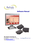
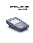
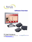
TTL-DAQ DEMO Application Note for National Instrument User Thought Technology Ltd. 8205 Montreal/ Toronto Blvd. Suite 223, Montreal West, Quebec, Canada H4X 1N1 Tel: (800) 361-3651 ۰ (514) 489-8251 Fax: (514) 489-8255 E-mail: [email protected] Webpage: www.thoughttechnology.com/sciencedivision/index.html SAN0001-00 Application Note for National Instrument User Page 2 INTRODUCTION Thought Technology’s Science Division provides researchers and biomedical engineering students a reliable and accurate way to measure important bio signals using our physiological sensors along with National Instruments’ data acquisition (DAQ) system and LabVIEW™ software. Visit our website for more information regarding technical notes for sensors and solutions, as well as application notes for other third-party devices. For a quick summary of this application note, please consult the following videos: TTL-DAQ DEMO.VI - Interfacing Thought Technology Sensors with National Instruments NI cDAQ-9172 and LabVIEW, Hardware Setup Tutorial http://www.youtube.com/watch?v=WvIivFKWleI TTL-DAQ DEMO.VI - Interfacing Thought Technology Sensors with National Instruments NI cDAQ-9172 and LabVIEW, Software Demo Tutorial http://www.youtube.com/watch?v=VgnoxnXmL60 OBJECTIVE This application note will provide the intended user(s) with step-by-step instructions on how to: quickly and safely interface Thought Technology sensors to a National Instruments’ DAQ system set up the provided software demo VI to acquire and process live physiological signals such as EMG, heart rate, temperature, and respiration adapt the provided software demo VI for your applications SAN0001-00 Application Note for National Instrument User Page 3 TTL-DAQ DEMO RESOURCE LIST The following Thought Technology products will be used in this demonstration. We strongly encourage you to review each product’s technical note for detailed specifications and user guidelines. Additional accessories (e.g. power adaptor, cables, skin prep, conductive gel, electrodes, PolarTM transmitter belt) will also be needed to properly carry out this demonstration. TT Sensor Isolator (SE9405AM) The Sensor Isolator is an interface device which provides electrical isolation (4.5kV, providing two means of protection). It allows Thought Technology sensors to be safely interfaced with analog inputs of line-powered systems, such as computers with DAC cards. Additional accessories: SE9408 power adaptor, SA9409BNC/SA9409PGT or two user supplied 3.5mm stereo male-to-male cables, and 9V battery. MyoScan EMG Sensor (T9503M) The MyoScan sensor is a differential amplifier for surface electromyography (sEMG). Surface EMG is a noninvasive measure of underlying muscle activity by detecting and amplifying tiny electrical impulses generated by muscle fibers when they contract. Additional accessories: NuPrep (10-30), conductive gel (10-20-4T), UniGel electrodes (T3425) with extender cable (T8720M) or Triode electrode (T3402M). EKG Receiver for Polar (SA9330) The EKG Receiver detects the heart rate of a user from the Polar transmitter belt T31, T31c and WearLink®+ (not provided) that the user wears around the chest. Note that PolarTM transmitter belt T31, T31c or WearLink®+ is not provided by Thought Technology and must be purchased separately. SAN0001-00 Application Note for National Instrument User Page 4 pIR Sensor (T2600) The pIR sensor is a passive infrared temperature sensor for measuring radiated temperature in the infrared range. It is used to measure the changes in forehead temperature when attached to the pIR HEadGearTM. Respiration Sensor (SA9311M) The respiration signal is a relative measure of abdomen expansion. The Respiration Sensor is a sensitive girth sensor using an easy fitting high durability latex rubber band fixed with self-adhering belt. It detects chest or abdominal expansion/contraction and shows the respiration waveform and amplitude. It can be worn over clothing. PC REQUIREMENTS Minimum system environment: Core 2 Duo, 1GB RAM, Windows 7/Vista/XP SP3 Requires LabVIEW version 11.0.1 or later to explore or modify project files. If you wish to only run the executable of the demonstration provided, visit www.ni.com to download and install LabVIEW Run-Time Engine 2011 "LVRTE2011f3std.exe". Requires DAQ-mx driver to be installed if acquiring live signals from NI DAQ hardware. Playback mode option is available to simulate acquisition of physiological signals without use of sensor or NI DAQ hardware. INTERFACING THOUGHT TECHNOLOGY SENSORS WITH NATIONAL INSTRUMENTS’ DATA ACQUISITION SYSTEM Choosing Your NI DAQ Device: National Instruments provides a wide selection of PC-based DAQ devices and modular systems. The following recommendation serves as our general guideline for ensuring the specified performance for all Thought Technology sensors: Recommended Specifications for DAQ Hardware Recommended resolution of 0.15mV (16-bit ADC over 10V span) or better Minimum input range: ±5V (bipolar, via SE9405AM TT Sensor Isolator) SAN0001-00 Application Note for National Instrument User Page 5 For applications involving EEG or EMG signals, the recommended specifications are required. For other applications, the user may choose a lower resolution DAQ device. This is acceptable depending on the user's required resolution (if known), the nature of the acquired signal, and the type of signal processing to be done. Examples of sensor signals that may be compatible with a lower resolution (14 bit) DAQs are Polar EKG, HR/BVP, respiration, and goniometer, bend sensor, InclinoTrac, and force sensor. Selecting an Interface Cable: Most NI DAQ devices are available in one of the following I/O connector option: screw terminal, spring terminal, or BNC. Based on your I/O connector option, you will need to choose the appropriate interfacing cable for making the wired connections from the TT Sensor Isolator to the DAQ input. For screw terminal and spring terminal connector inputs, we recommend the DB15-to-pigtail break-out cable (SA9409PGT). As an alternative, the users may also prepare two 3.5mm stereo-to-pigtail break-out cables. See “User Manual Sensor Isolator SE9405AM” for details. For BNC connector inputs, we recommend the DB15-to-BNC break-out cable (SA9409BNC). Making Interface Connections: For demonstration purposes, we used the NI 9215 module (screw terminal option) with NI cDAQ-9172 CompactDAQ chassis. This DAQ setup provides 4 differential analog inputs at 16bit resolution with an adjustable input range of up to +/-10V (select software to use +/-5V). Many other NI DAQ systems are available and are equally compatible. See the previous section "Choosing Your NI DAQ Device" for selection guidelines. The following steps detail the physical connections for setting up the 4 predefined physiological sensors with the TT Sensor Isolator (SE9405AM) and connecting them to a typical NI DAQ system. 1. Connect each of the 4 physiological sensors to the TT Sensor Isolator using the provided sensor cables in the following order: Input CH1 - MyoScan EMG Sensor Input CH2 - EKG Receiver for Polar Heart Rate Input CH3 - TT-Infra / pIR Temperature Sensor Input CH4 - Respiration Sensor SAN0001-00 Application Note for National Instrument User Page 6 Note: Align the white dot on the cable with the notch on the connector. 2. As mentioned, the NI DAQ module we are using has a screw terminal connector. Therefore choosing the DB15-to-pigtail break-out cable (SA9409PGT), we will make the wired connections from the TT Sensor Isolator to the screw terminal on the DAQ inputs. Connect the DB15 cable to the TT Sensor Isolator. On the pig-tail end, connect CH1 signal to AI0+ and ground to AI0-. Keeping in mind it is preferable to make each connection in a logical sequence, connect the remaining 3 channels. 3. The output side of the TT Sensor Isolator is considered a floating source and is supplied by the provided power adaptor. The voltage on the output side SIG lines will span 2.8 +/2V relative to the GND lines. All output side GND lines are tied together. Many NI DAQ systems (except ones with internal biasing circuits) require the user to place external resistors for biasing each analog input. This is required in the setup to ensure proper measurement of the desired signal and reduce unwanted noise pick up. The following diagram shows the electrical configuration of the external resistors. Physically, these resistors can be placed directly across the inputs on the DAQ connector block. If AI GND is not available, use the COM input. External resistors are needed in either DAQ input configurations: differential or single-ended non-referenced. For more details regarding the use of external resistors for biasing a floating signal SAN0001-00 Application Note for National Instrument User Page 7 source, see "Field Wiring and Noise Considerations for Analog Signals" http://www.ni.com/white-paper/3344/en 4. Connect the provided power adapter to the TT Sensor Isolator to supply the output side of the unit. Ensure the 9V battery inside the unit is functional (supplies power to the sensor side) by turning the TT Sensor Isolator ON. A bright blue light should turn ON. 5. Turn ON the NI DAQ system. SETUP OF TTL-DAQ DEMO.VI ACQUIRING AND PROCESSING PHYSIOLOGICAL SIGNALS 1. Download the TTL-DAQ DEMO project from www.thoughttechnology.com/sciencedivision/media/TTL_DAQ_DEMO.zip 2. Unzip the folder. Find and open "TTL-DAQ DEMO.lvproj". 3. Connect each physiological sensor to a participant subject's body following the methods described for each sensor in their respective Technical Notes series. 4. Open "TTL-DAQ DEMO.vi" and click on the "Setup" tab. Under "NI Acquisition Hardware", select the appropriate DAQ device and input choices for Physical CH1 to CH4. These choices should also correspond to the sensors connected to CH1 through 4. SAN0001-00 Application Note for National Instrument User Page 8 5. Run the demo VI. A pop-up window will appear. Ensure "Playback Mode" is unselected, and then click Start. If Playback Mode is selected, no hardware setup is required and the demo VI will display pre-recorded physiological signals. 6. Examine each signal tab as live physiological signals are acquired and processed from a participant subject. ADAPTING SOFTWARE DEMO VI FOR USER APPLICATIONS The TTL-DAQ DEMO.VI demonstrates how to acquire, process, and display predefined SAN0001-00 Application Note for National Instrument User Page 9 physiological signals. The provided demo VI may also be adapted by the user to acquire, process, and display signals for other physiological sensors. Programming Walkthrough of TTL-DAQ DEMO.VI Going to the back panel, note the VI is structured into 3 distinct parts: an initialize sequence, a main loop, and a terminate sequence. The program begins by initializing the DAQ hardware according to various pre-defined settings and the physical channels defined by the user. Here, certain program variables and arrays are also initialized. In the main loop, a nested sequence structure executes a series of tasks inside a while loop. We start with acquiring the raw data from the DAQ. SAN0001-00 Application Note for National Instrument User Page 10 Then we scale the raw data according to the user selected sensor type. The sub VI “TTL Sensor Type.vi” is available in the project folder and provides the mapping required to turn raw DAQ acquired voltages into meaningful sensor units for all Thought Technology sensors. In the nested sequence frames 2-5, each frame is strictly devoted to the processing and display of the 4 signal types. As an example, we can look at CH1 EMG. Of the 4 signal types, this is the most heavily processed signal. Filtering options can be defined by the user while running the VI. Custom filtering VIs provide up to three cascaded Butterworth filters to be applied to the data array and the result is sent to another custom VI that performs an RMS averaging on the data array. SAN0001-00 Application Note for National Instrument User Page 11 The filtered data array is also sent to a custom FFT averager that processes, and then displays the result. Finally the data array is placed in the display array where a sliding window plots a segment of data to the front panel. For the remaining channels, some processing is typically required to extract meaningful parameters. For CH2’s Polar heart rate signal (nested sequence frame 3), we compute the time interval between peak pulses based on the number of samples and sampling rate. The computed instantaneous HR value is averaged with the results of the 10 previous values, and then displayed. On CH3 the temperature sensor (nested sequence frame 4), the raw signal is scaled, a low pass filter at 3HZ is applied, and the resulting signal is then displayed. As for the respiration sensor on CH 4 (nested sequence frame 5), no processing was developed. The raw signal is simply scaled according to the mapping selected by the user and provided by the TTL Sensor Type.VI. The scaled signal is then displayed. Should the user wish to replace the attached respiration sensor for a different sensor, the proper scaled signal can easily be selected and the resulting waveform will continue to be displayed. In the nested sequence frame 6, the display data from each of the previous sequence frames is synchronously updated to the 4 display graphs in the BioSensor DEMO tab. SAN0001-00 Application Note for National Instrument User Page 12 Finally, in the terminate section, we close the DAQ resource and any other resources that were previously opened. Reusable VIs From This DEMO The TTL-DAQ DEMO.vi has demonstrated how to easily acquire, scale, and display Thought Technology physiological signals in LabVIEW using non-specific NI DAQ systems. The challenge that remains for the user will be to develop their own application specific processing algorithms for each of the different physiological signal required in their setup. There are 5 subVIs available from the demo project folder. They may serve as a helpful starting point for users interested in developing their own applications, and may be reused or modified. SAN0001-00 Application Note for National Instrument User Page 13 SAN0001-00 Application Note for National Instrument User Page 14