1
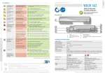
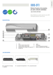
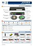
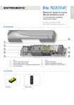
Download the BEA DECODER app
for a quick overview
of settings
ENGLISH
IXIO-DT3
Opening & safety sensor
for automatic sliding doors
(according to EN 16005 and DIN 18650,
including emergency exits)
User’s Guide for product version 0400 and higher
See product label for serial number
DESCRIPTION
6
1
2
3
7
4
8
5
9
1.
2.
3.
4.
5.
LCD
radar antenna (narrow field)
radar antenna (wide field)
IR-curtain width adjustment
IR-lenses
6.
7.
8.
9.
cover
main connector
main adjustment knob
IR-curtain angle adjustment knob
ACCESSORIES
BA: Bracket accessory
CA: Ceiling accessory
RA: Rain accessory
Retrofit interface
Door bell + interface
Smart Daisy Chain hub
CDA: Curved door accessory
9 V battery
HOW TO USE THE LCD?
Display during normal functioning
Opening
impulse
To adjust contrast, push and turn
the grey button simultaneously.
Negative display = active output
Safety
During normal function only.
FACTORY VALUE VS. SAVED VALUE
displayed value = saved value
displayed value = factory value
NAVIGATING IN MENUS
Push to enter
the LCD-menu
Password
XXXX
Enter password if
necessary
Select your language before
entering the first LCD-menu.
Not during the first
minute after power-on
of the sensor.
During the first 30 seconds after
power-on of the sensor or later in
the diagnostics menu.
Select More to go to
next level:
- basic settings
- advanced settings
- diagnostics
Select Back to
return to previous
menu or display.
Scroll menu
items
CHANGING A VALUE
6
6
Push to
select
parameter
Scroll
menu
up-down
current value is
displayed
Scroll
values
up-down
more values are
displayed
Push
to save
new value
new value is
displayed
CHANGING A ZIP CODE
See application note on ZIP CODE
ZIP code
ID #
...
ZIP code
H24 1 56-KG4
01 0 800/02D
ZIP code
E24 1 56 KG4
01 0 800 02F
ZIP code
E24 1 56-KG4
01 0 800/02F
ZIP code
V
ZIP code
E24 1 56-KG4
01 0 800/02F
ZIP code
H24 1 56-KG4
01 0 800/02F
Validate the last digit in order to activate the new ZIP code:
- v = valid ZIP code, values will be changed accordingly
- x = invalid ZIP code, no values will be changed
- v/x = valid ZIP code, but from a different product.
Only available values will be changed.
VALUE CHECK WITH REMOTE CONTROL
Pressing a parameter symbol on your remote control,
displays the saved value directly on the LCD-screen.
Do not unlock first.
2
ZIP code
H24 1 56-KG4
01 0 800/02F
IXIO-DT3: INSTALLATION GUIDE
MOUNTING & WIRING
GREEN
12-24 V
AC-DC
POWER SUPPLY
BROWN
YELLOW
*
OPENING INPUT
WHITE
**
. 5 cm
max
PINK
SENSOR
*
GREY
TEST
OUTPUT
BLUE
YE/BK +
OPENING INPUT
FOR CURRENT
SOURCE
WH/BK -
* Output status when sensor is operational
** For compliance with EN 16005 and DIN 18650,
connection to door controller test output is required.
***Current source output for emergency exits
Fixation is compatible with the ACTIV8.
RADAR OUTPUT CONFIGURATION
RELAY OUTPUT
SAFETY INPUT
RED
***
2
ENGLISH
1
OR
NO: normally open
NC: normally closed
FREQUENCY OUTPUT
for emergency exits
YE/BK +
for emergency exits
WH/BK -
RADAR OPENING IMPULSE FIELD
field size: 9
immunity: 2
ANGLE
3
CURRENT SOURCE OUTPUT
field size: 9
immunity: 2
2.2 m
2.2 m
from 15° to 45°, default 30 °
from -15° to 15°, default 0°
WIDTH
field size: 9
immunity: 2
2.2 m
4 m x 2 m (wide)
field size: 9
immunity: 2
2.2 m
2 m x 2.5 m (narrow)
The size of the detection field varies according to the mounting height of the sensor.
In emergency exits the full door width must be covered.
3
4
ANGLE
INFRARED SAFETY FIELD
door
CLOSER
max.
9 cm**
AWAY
OR
Activate the visible* spots to verify
the position of the IR-curtain.
If necessary, adjust the IR-curtain
angle (from -7° to 4°, default 0°).
WIDTH
* Visibility depends on external conditions. When spots are not visible, use the Spotfinder to locate the curtains.
** The distance between the inner curtain of the inside door sensor and the inner curtain of the outside door sensor should
always be smaller than 20 cm. The distance to the door leaf depends therefore on the thickness of the door leaf.
Additional
adjustments
are possible by
LCD or remote
control
(see p. 5)
Part of the detection field can be masked to reduce it.
The arrow position determines the width of the detection field.
Mounting
height
Detection
width
2.00 m
2.20 m
2.50 m
3.00 m
3.50 m
2.00 m
2.20 m
2.50 m
d max
d max
3.50
3,50 m
m
DIN 18650
BS 7036
dd max
max == 2.5
2,5 m
m
5
Always verify the actual detection field width
with a piece of paper and not the Spotfinder,
which detects the whole emitted field.
3,50 m
3.50
EN 16005
33 m
m
3m
2.50
2,50 m
m
2,50 m
2.50
22 m
m
2m
The size of the detection field varies according to the
mounting height and the settings of the sensor.
The full door width must be covered.
d max = 3 m
SETTINGS
OR
Choose one of the following presettings or adjust the sensor manually (see p.5):
standarD: standard in- and outdoor installations
critical environment: critical installations due to surroundings or weather
shopping street: installations in narrow streets with pedestrian traffic
6
SETUP
Step out of the INFRARED field!
setup 1 (quick)
reference picture
setup 2 (ASSISTED)
test of full door cycle +
reference picture
+
OR
+
2s
+
4s
Test the good functioning of the installation before leaving the premises!
4
OVERVIEW OF SETTINGS
0
1
2
3
4
Back
More
BASIC
Rad: Fieldsize
small
Rad: Output
IR: Immunity
IR: FreqUENCY
>
>
NO
NC
NC
NO
low
normal
A
B
>
NC
NC
6
7
8
9
factory values for radar immunity, IR immunity, IR number and redirection
increased immunities, 1 curtain
increased immunities, redirection = motion and presence
shopping
standard critical street
env.
PresettingS
5
>
>
>
NO
NO
current
NC
freq
NC
>
< 2.8 m
> 2.8 m
high higher highest normal high
Sensors mounted close to each other should
have a different frequency.
More
Back
large
NO: normally open
NC: normally closed
freq: frequency output
current: current output
For conformity to EN 16005 or DIN 18650 at a
mounting height of 2.8 or more, use values 6 and 7.
For conformity to BS 7036 at a mounting height
of 2.2 m or more, use values 6 and 7.
excludes conformity of the door system
according to EN 16005 / DIN 18650 / BS 7036
factory value
not allowed when the sensor is used in emergency exits
Back
More
ADVANCED
Rad: Immunity
low
Rad: Direction
radar
off
bi
uni
Rad: Holdtime
0.5 s
1s
2s
>
>
>
>
>
uni
uni
AWAY
uni
auto
PRM
PRM
bi
auto
auto
3s
4s
5s
6s
7s
>
8s
9s
IR: Width
Always additionally adjust
the arrow position on the
sensor with a screwdriver.
+
IR: Number
service
mode
1
2
IR: PresENCE time
motion
15 s
30 s
1 min
2 min
5 min
10 min
NO
NC
NC
NO
NC
NC
NO
NO
current
NC
freq
NC
IR: Output
Redirection
SMART DAISy CHAIN*
motion
motion
or
presence
off
1/2
service mode = no IR detection during 15 minutes (maintenance).
This value excludes conformity of the door system to EN 16005 and DIN 18650.
min. value for DIN18650: 1 min
20 min 60 min infinite min. value for EN16005: 30 s
NO: normally open
NC: normally closed
motion opening output is active in case of: 0 motion detection
and
1 motion or presence detection
presence 2 motion and presence detection
2/2
1/3
2/3
3/3
1/2: 1st sensor in chain of 2; 2/2: 2nd sensor in chain of 2
1/3: 1st in chain of 3; 2/3: 2nd in chain of 3; 3/3: 3rd in chain of 3
Factory rEsEt
DOOR BELL*
off
0.05 s
0.10 s
0.25 s
0.50 s 0.75 s
More
Back
DIAGNOSTICS
high
PRM: for persons with reduced mobility
AWAY: unidirectional motion away from sensor
auto: automatic adaptation of field size (small shops)
Zip CODE
ID #
Error Log
IR: spotview
IR: C1 Energ
IR: C2 Energ
1s
1.5 s
full
reset
partial
reset
2s
5s
partial: outputs are
not reset
* Setting in combination with an accessory (see p. 1).
For more information see user’s guide of accessory.
all parameter settings in zipped format
(see application note on ZIP CODE)
unique ID-number
last 10 errors + day indication
view of spot(s) that trigger detection
signal amplitude received on curtain 1
signal amplitude received on curtain 2
PowerSupply
OperatingTime
RESET LOG
Password
Language
Admin
supply voltage at power connector
power duration since first startup
delete all saved errors
LCD and remotre control password (0000= no password)
language of LCD-menu
enter code to access admin mode
5
TROUBLESHOOTING
E1
E2
E4
E5
E6
E7
E8
E9
ORANGE LED flashes 1 x.
The sensor signals
an internal fault.
1
Replace sensor.
ORANGE LED flashes 2 x.
The power supply is too
low or too high.
1
2
Check power supply (in the diagnostics menu of the LCD).
Check wiring.
ORANGE LED flashes 4 x.
The sensor receives
not enough IR-energy.
1 Decrease the angle of the IR-curtains.
2 Increase the IR-immunity filter (values >2.8 m).
3 Deactivate 1 curtain.
ORANGE LED flashes 5 x.
The sensor receives
too much IR-energy.
1 Slightly increase the angle of the IR-curtains.
2 Decrease the IR-immunity filter (values 1-3 <2.8 m).
The sensor is disturbed by
external elements.
1
ORANGE LED flashes 6 x.
Faulty radar sensor output
1 Replace sensor.
ORANGE LED flashes 7 x.
The internal test of the
radar is disturbed.
1 Change radar field angle or antenna.
2 Launch a quick setup.
3 If orange LED flashes again, replace sensor.
ORANGE LED flashes 8 x.
IR power emitter is faulty.
1 Replace sensor.
ORANGE LED flashes 9 x.
Internal reference of the
radar is faulty.
1 Replace sensor.
ORANGE LED is on.
The sensor encounters
a memory problem.
1
2
Cut and restore power supply.
If orange LED lights up again, replace sensor.
RED LED flashes
quickly after an
assisted setup.
The sensor sees the door
during the assisted setup.
1
2
Move the IR-curtains away from the door.
Install the sensor as close to the door as possible.
If needed, use a bracket accessory.
Launch a new assisted setup.
1
2
4
5
6
7
8
9
3
Check if the sensor is fastened firmly.
Check position of cable and cover.
The sensor sees the door.
1
2
1
The sensor is disturbed
by external conditions.
1
2
Increase the IR-immunity filter to value 3.
Select presetting 2 or 3.
The sensor is disturbed by
rain and/or leaves.
1
2
Select presetting 2 or 3.
Increase radar-immunity filter.
Ghosting created by door
movement.
1
Change radar field angle.
The sensor vibrates.
1
2
Check if the sensor and door cover is fastened firmly.
Check position of cable and cover.
The sensor sees the door
or other moving objects.
1
2
Remove the objects if possible.
Change radar field size or angle.
The LED and the LCDdisplay are off.
1
Check wiring.
The reaction of the door
does not correspond to
the LED-signal.
1
2
Check output configuration setting.
Check wiring.
1
Enter the right password. If you forgot the code, cut
and restore the power supply to access the sensor
without entering a password during 1 minute.
RED LED lights up
sporadically.
GREEN LED lights up
sporadically.
The LCD or remote
control does not react.
6
Eliminate the cause of disturbance (lamps, rain cover,
door controller housing properly grounded).
The sensor vibrates.
The sensor is protected by a
password.
Launch an assisted setup and adjust the IR angle.
LED-SIGNAL
Presence
detection
Motion
detection
LED flashes
LED flashes
x x times
LED flashes
red-green
LED flashes
quickly
LED is off
INSTALLATION
The sensor should be
fixed firmly to avoid
extreme vibrations.
Do not cover the sensor.
Avoid moving objects
and light sources in
the detection field.
Avoid highly
reflective objects in
the infrared field.
MAINTENANCE
It is recommended to clean
the optical parts at least once
a year or more if required due
to environmental conditions.
Do not use aggressive
products to clean
the optical parts.
SAFETY
The door control unit
and the door cover
profile must be correctly
earthed.
•
•
•
Only trained and
qualified personnel
may install and setup
the sensor.
Always test the good
functioning of the
installation before
leaving the premises.
The warranty is invalid if
unauthorized repairs are
made or attempted by
unauthorized personnel.
The device cannot be used for purposes other than its intended use. All other uses cannot be
guaranteed by the manufacturer of the sensor.
The manufacturer of the door system is responsible for carrying out a risk assessment and installing the
sensor and the door system in compliance with applicable national and international regulations and
standards on door safety.
The manufacturer of the sensor cannot be held responsible for incorrect installations or inappropriate
adjustments of the sensor.
7
TECHNICAL SPECIFICATIONS
12 V - 24 V AC +/-10% ; 12 V - 30 V DC +/-10% (to be operated from SELV compatible power supplies only)
< 2.5 W
2 m to 3.5 m (local regulations may have an impact on the acceptable mounting height)
-25°C to +55°C; 0-95% relative humidity, non condensing
IP54
< 70 dB
20 years
R&TTE 1999/5/EC; MD 2006/42/EC; LVD 2006/95/EC; ROHS 2 2011/65/EU
Detection mode:
Motion
Min. detection speed: 5 cm/s
Presence
Typical response time: < 200 ms (max. 500 ms)
Technology:
Microwave doppler radar
Transmitter frequency: 24.150 GHz
Transmitter radiated power: < 20 dBm EIRP
Transmitter power density: < 5 mW/cm2
Active infrared with background analysis
Spot: 5 cm x 5 cm (typ)
Number of spots: max. 24 per curtain
Number of curtains: 2
Output:
Solid-state-relay (potential and polarity free)
Max. contact current: 100 mA
Max. contact voltage: 42 V AC/DC
Solid-state-relay (potential and polarity free)
Max. contact current: 100 mA
Max. contact voltage: 42 V AC/DC
Holdtime: 0.3 to 1 s
- in switching mode: NO/NC
- in frequency mode: pulsed signal
(f= 100 Hz +/- 10%)
Galvanically isolated current source
No detection: current source ON
Open circuit voltage: 6.5 V
Output voltage available at 10 mA: 3 V min.
Typical load: up to 3 optocouplers in series
Detection: current source OFF
Open-circuit remained voltage: < 500 mV
Sensitivity: Low: < 1 V; High: > 10 V (max. 30 V)
Response time on test request: typical: < 5 ms
Test input:
Norm conformity:
EN 12978
EN ISO 13849-1:2008 PL «d» CAT. 2
EN 16005:2012 Chapter 4.6.8;
DIN 18650-1:2010 Chapter 5.7.4; AutSchR
BS 7036-1:1996 Chapter 7.3.2
(only applicable for relay output in frequency mode
and current source output)
A
E
N
A
B L
E S
O
A C C
R
D
A
N
A
EN 12978
EN ISO 13849-1:2008 PL «c» CAT. 2
(under the condition that the door control system
monitors the sensor at least once per door cycle)
IEC 61496-1:2012 ESPE Type 2
EN 16005:2012 Chapter 4.6.8;
DIN 18650-1:2010 Chapter 5.7.4
BS 7036-1:1996 Chapter 8.1
Specifications are subject to changes without prior notice.
All values measured in specific conditions.
C
E
W I
T H
50
186
DIN
E
N
N
W I
T H
E
C
N
E R L AU
BT
E
05
160
Z I E RUNG
FI
TI
H
H
EN
R
Z
N
E R L AU
BT
Z I E RUNG
FI
TI
Z
R
C
E
C
©BEA | Original instructions | 42.8302 / V1 - 10.14
Please keep for further use - Designed for colour printing
Supply voltage:
Power consumption:
Mounting height:
Temperature range:
Degree of protection:
Noise:
Expected lifetime:
Applicable directives:
A
B L
E S
O
A C C
R
D
A
BEA SA | LIEGE Science Park | ALLÉE DES NOISETIERS 5 - 4031 ANGLEUR [BELGIUM] | T +32 4 361 65 65 | F +32 4 361 28 58 | [email protected] | WWW.BEA.BE
BEA hereby declares that the IXIO-DT3 is in conformity with the basic requirements and the other relevant provisions of the directives
1999/5/EC, 2006/95/EC and 2006/42/EC.
Notified Body for EC-type inspection: 0044 - TÜV NORD CERT GmbH, Langemarckstr. 20, D-45141 Essen
EC-type examination certificate number: 44 205 12 405836-001
Angleur, October 2014
Pierre Gardier, authorized representative and responsible for technical documentation
The complete declaration of conformity is available on our website: www.bea-pedestrian.be
Only for EC countries: According to the European Guideline 2012/19/EU for Waste Electrical and Electronic Equipment (WEEE)