1
PISO-CAN400-D/T
PISO-CAN200-D/T
User’s Manual
Warranty
All products manufactured by ICP DAS are warranted
against defective materials for a period of one year from the
date of delivery to the original purchaser.
Warning
ICP DAS assumes no liability for damages consequent
to the use of this product. ICP DAS reserves the right to
change this manual at any time without notice. The
information furnished by ICP DAS is believed to be accurate
and reliable. However, no responsibility is assumed by ICP
DAS for its use, or for any infringements of patents or other
rights of third parties resulting from its use.
Copyright
Copyright 2004 by ICP DAS Co., LTD. All rights
reserved worldwide.
Trademark
The names used for identification only may be
registered trademarks of their respective companies.
PIO-CAN400/200 User’s Manual
(Ver :1.1 01/27/05)
1
Contents
1.
GENERAL INFORMATION .................................................................................4
1.1 INTRODUCTION ..........................................................................................................4
1.2 FEATURES ..................................................................................................................4
1.3 SPECIFICATIONS .........................................................................................................4
1.4 PRODUCT CHECK LIST ...............................................................................................5
2.
HARDWARE CONFIGURATION .......................................................................6
2.1 BOARD LAYOUT ..........................................................................................................6
2.2 JUMPER SELECTION ...................................................................................................8
2.3 CONNECTOR PIN ASSIGNMENT ....................................................................................9
2.3.1 5-pin screw terminal connector ......................................................................9
2.3.2 9-pin D-sub male connectors ........................................................................10
2.4 INSTALLATION ..........................................................................................................10
3.
SOFTWARE INSTALLATION ...........................................................................11
4.
INSTALLATION DLL DRIVER .........................................................................12
4.1 DLL FUNCTION DEFINITION AND DESCRIPTION ........................................................12
4.1.1 CAN_GetDllVersion .......................................................................................13
4.1.2 CAN_TotalBoard ............................................................................................14
4.1.3 CAN_GetBoardInf...........................................................................................15
4.1.4 CAN_ActiveBoard...........................................................................................16
4.1.5 CAN_CloseBoard............................................................................................16
4.1.6 CAN_BoardIsActive........................................................................................17
4.1.7 CAN_Reset ......................................................................................................17
4.1.8 CAN_Init .........................................................................................................18
4.1.9 CAN_Config....................................................................................................19
4.1.10 CAN_EnableRxIrq ........................................................................................21
4.1.11 CAN_DisableRxIrq .......................................................................................22
4.1.12 CAN_RxIrqStatus..........................................................................................23
4.1.13 CAN_InstallIrq..............................................................................................24
4.1.14 CAN_RemoveIrq ...........................................................................................25
4.1.15 CAN_IrqStatus ..............................................................................................26
4.1.16 CAN_Status ...................................................................................................27
4.1.17 CAN_SendMsg ..............................................................................................29
4.1.18 CAN_RxMsgCount........................................................................................30
PIO-CAN400/200 User’s Manual
(Ver :1.1 01/27/05)
2
4.1.19 CAN_ReceiveMsg .........................................................................................31
4.1.20 CAN_ClearSoftBuffer ...................................................................................32
4.1.21 CAN_ClearDataOverrun ..............................................................................33
4.1.22 CAN_GetSystemFreq ....................................................................................33
4.2 TABLE OF RETURN CODE ..........................................................................................34
4.3 FLOW DIAGRAM FOR APPLICATION ...........................................................................35
5.
DEMO PROGRAMS FOR WINDOWS..............................................................38
6.
UTILITY PROGRAM FOR WINDOWS ...........................................................41
APPENDIX.....................................................................................................................44
ACCEPTANCE FILTERING...............................................................................................44
PIO-CAN400/200 User’s Manual
(Ver :1.1 01/27/05)
3
1.General Information
1.1 Introduction
The CAN (Controller Area Network) is a serial communication protocol, which
efficiently supports distributed real-time control with a very high level of security.
It is especially suited for networking "intelligent" devices as well as sensors and
actuators within a system or sub-system. In CAN networks, there is no
addressing of subscribers or stations in the conventional sense, but instead
prioritized messages are transmitted. As a standalone CAN controller, PIOCAN400/CAN200 represents an economic solution within which an active CAN
board can have either two or four independent CAN bus communication ports
with either a 5-pin screw terminal connector or a 9-pin D-sub connector. It can
be used as master/slave function to cover a wide range of CAN applications. In
addition, the PIO-CAN400/CAN200 uses the new Phillips SJA1000T and
transceiver 82C250/251, which provide for bus arbitration and error detection
with both an auto correction and re-transmission function. It can be installed in a
5V 32-bit PCI slot and is supported with actual “Plug & Play” technology.
1.2 Features
z
PCI BUS interface;
z
2500Vrms photo-isolation protection.
z
Four or two independent CAN communication ports.
z
Compatible with CAN specification 2.0 parts A and B.
z
On-board optical isolation protection.
z
Programmable transfer-rate up to 1 Mbps.
z
Jumper select 120Ω terminator resistor for each port.
z
Direct memory mapping to the CAN controllers.
z
33MHz 32bit 5V PCI bus (V2.1) plug and play technology.
z
Driver supported for Windows 98/ME/NT4/2000/XP
1.3 Specifications
z
CAN controller: Phillips SJA1000T.
PIO-CAN400/200 User’s Manual
(Ver :1.1 01/27/05)
4
z
CAN transceiver: Phillips 82C250/251.
z
Signal support: CAN_H, CAN_L.
z
16 MHz CAN controller frequency.
z
Connector: 5-pin screw terminal connector or 9-pin D-sub male
connector.
z
Isolation voltage: 2500Vrms.
z
Power requirements:
CAN400: 5V@640mA
CAN200: 5V@380mA
z
Environmental:
Operating temp: 0~60℃
Storage temp: -20~80℃
Humidity: 0~90% non-condensing
Dimensions: 130mm X 110mm
1.4 Product Check List
In addition to this manual, the package includes the following items:
PIO-CAN400/CAN200 card;
ADP-9 Board (for PIO-CAN400 only)
Software CD ROM;
User manual.
It is recommended that users read the release note first. All the
important information needed will be provided in the release note as
follows:
Where you can find the software driver, utility and demo programs.
How to install software & utility.
Where is the diagnostic program?
FAQ’s and answers.
Attention !
If any of these items are missing or damaged, please contact
your local field agent. Keep aside the shipping materials and carton in
case you want to ship or store the product in the future.
PIO-CAN400/200 User’s Manual
(Ver :1.1 01/27/05)
5
2.Hardware Configuration
This section will describe the hardware settings of the PIO-CAN, which
includes the settings for both the PIO-CAN400 and the PIO-CAN200.
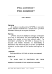
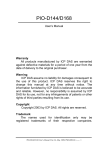
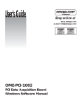
2.1 Board Layout
Figure2.1 PIO-CAN200 Board LAYOUT
PIO-CAN400/200 User’s Manual
(Ver :1.1 01/27/05)
6
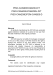
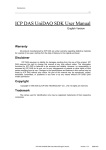
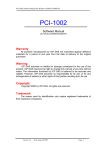
Figure2.2 PIO-CAN400 Board LAYOUT
Figure2.3 ADP-9 Board LAYOUT (For PIO-CAN400 Only)
PIO-CAN400/200 User’s Manual
(Ver :1.1 01/27/05)
7
2.2 Jumper Selection
Table 2.1 Jumper Selections
Jumper
Description
Status
JP1
JP1
CAN Port 3 Connector,
connecting PIO-CAN400
board and ADP-9 board.
JP1
1
2
3
1 2 3
Pin1: CAN_L
Pin2: CAN_H
Pin3: Shield
JP2
JP2
CAN Port 4 Connector,
connecting PIO-CAN400
board and ADP-9 board.
JP2
1
2
3
1 2 3
Pin1: CAN_L
Pin2: CAN_H
Pin3: Shield
JP6
Port 1 terminator
resister(120Ω) selection
Enable
Disable
1 2 3
1 2 3
JP7
Port 2 terminator
resister(120Ω) selection
1 2 3
1 2 3
JP8
Port 3 terminator
resister(120Ω) selection
1 2 3
1 2 3
JP9
Port 4 terminator
resister(120Ω) selection
1 2 3
1 2 3
PIO-CAN400/200 User’s Manual
(Ver :1.1 01/27/05)
8
2.3 Connector Pin Assignment
The PIO-CAN400-T/PIO-CAN200-T are equipped with four/two sets of 5pin screw terminal connectors and the PIO-CAN400-D/PIO-CAN200-D are
equipped with four/two sets of 9-pin D-sub male connectors for wire
connection of the CAN bus. The connector’s pin assignment is specified as
follows:
2.3.1 5-pin screw terminal connector
The 5-pin screw terminal connector for the CAN bus is shown in Figure 2.4.
The details for the pin assignment are presented in Table 2.2.
1
2
3
4
5
CAN-L Shield CAN-H
Figure2.4 5-pin screw terminal connector
Table 2.2: Pin assignment of 5-pin screw terminal connector
5-pin screw terminal connectors
pin assignment
1
No Use
2
CAN_L
3
Shield
4
CAN_H
5
No Use
PIO-CAN400/200 User’s Manual
(Ver :1.1 01/27/05)
9
2.3.2 9-pin D-sub male connectors
The 9-pin D-sub male connector of the CAN bus interface is shown in
Figure 2.5 and the corresponding pin assignments are given in Table 2.3.
CAN-L
1
2
6
Shield
3
4
5
7
8
9
CAN-H
Figure2.5 9-pin D-sub male connector
Table 2.3 Pin assignment of the 9-pin D-sub male connector
D-sub male connector pin
assignment
1
No Use
2
CAN_L
3
No Use
4
No Use
5
Shield
6
No Use
7
CAN_H
8
No Use
9
No Use
2.4 Installation
1. Configure the jumper settings on your PIO-CAN400/CAN200 in
accordance with your particular requirements.
2. Shutdown your system and take off the chassis of your machine.
3. Plug in your PIO-CAN400/CAN200 into a suitable empty PCI slot.
4. Replace your chassis.
PIO-CAN400/200 User’s Manual
(Ver :1.1 01/27/05)
10
5. Plug your CAN bus cable(s) into the 5-pin screw terminal connector or
the 9-pin D-sub connector.
6. When the hardware installation is complete, please turn on the computer
again.
3. Software Installation
The PIO-CAN400/CAN200 can be used in 98/Me/NT/2000/XP Windows
environments. For these Windows operation systems, the recommended
installation procedure is given as follows:
Step 1: Insert the companion CD into the CD-ROM driver and wait a few
seconds until the installation program starts automatically. If it
cannot be started automatically for some reason, please doubleclick the file \NAPDOS\AUTO32.EXE on this CD.
Step 2: Click the first item; Toolkits (Software) / Manuals.
Step 3: Click the item PCI Bus DAQ Card.
Step 4: Click PIO-CAN 400/200.
Step 5: Click “install Toolkit for Windows 98 (Or Me, NT, 2000, XP), which is
based on the operation system you used”.
Then the Install-Shield will start the driver installation process and copy the
related material to the indicated directory and then register the driver on your
computer. The driver target directory is as below for the different systems.
Windows NT/2000 – WINNT\SYSTEM32\DRIVERS
Windows 98/Me/XP – WINDOWS\SYSTEM32\DRIVERS
PIO-CAN400/200 User’s Manual
(Ver :1.1 01/27/05)
11
4. Installation DLL Driver
The DLL driver is the collection of function calls on the PIO-CAN400/CAN200
cards used for Windows 98/Me/NT/2000/XP systems. The application structure
is presented in the following figure. The user application programs which have
been developed by the following designated tools: VB, Delphi and Borland C++
Builder…etc, can call the PIOCAN.DLL driver in user mode. And then the DLL
driver will bypass the function call into the KP_CAN.sys and windrvr6.sys to
access the hardware system, as shown in the following Figure.
4.1 DLL Function Definition and Description
All the functions provided in the PIO-CAN400/200 are listed in the following
table and detailed information for every function is presented in the following
sub-section. However, in order to make the descriptions more simplified and
clear, the attributes for the both the input and output parameter functions are
given as [input] and [output] respectively, as shown in following table.
PIO-CAN400/200 User’s Manual
(Ver :1.1 01/27/05)
12
Keyword
Set parameter by user before Get the data from this parameter
calling this function?
after calling this function?
[ input ]
Yes
No
[ output ]
No
Yes
Table 4.1 DLL function definition
Function definition
Page
Int CAN_GetDllVersion();
14
Int CAN_TotalBoard();
14
Int CAN_GetCardInf(BYTE BoardNo, DWORD *dwVID, DWORD *dwDID,
DWORD *dwSVID, DWORD
*dwSDID, DWORD 15
*dwIrqNo);
Int CAN_ActiveBoard(BYTE wBoardNo)
16
Int CAN_CloseBoard(BYTE wBoardNo);
int CAN_BoardIsActive(BYTE BoardNo);
int CAN_Reset(BYTE BoardNo, BYTE Port);
int CAN_Init(BYTE wBoardNo, BYTE Port);
16
17
17
int CAN_Config(BYTE BoardNo, BYTE Port, ConfigStruct *CanConfig);
18
18
int CAN_EnableRxIrq(BYTE BoardNo ,BYTE Port);
20
int CAN_DisableRxIrq(BYTE BoardNo, BYTE Port);
20
int CAN_RxIrqStatus(BYTE BoardNo, BYTE Port, BYTE *bStatus);
21
int CAN_InstallIrq(BYTE BoardNo);
22
int CAN_RemoveIrq(BYTE BoardNo);
22
int CAN_IrqStatus(BYTE BoardNo, BYTE *bStatus);
23
int CAN_Status(BYTE BoardNo, BYTE Port, BYTE *bStatus);
24
int CAN_SendMsg(BYTE BoardNo, BYTE Port, PacketStruct *CanPacket);
25
int CAN_RxMsgCount(BYTE BoardNo, BYTE Port);
26
int CAN_ReceiveMsg(BYTE BoardNo, BYTE Port, PacketStruct *CanPacket); 27
int CAN_ClearSoftBuffer(BYTE BoardNo, BYTE Port);
28
int CAN_ClearDataOverrun(BYTE BoardNo, BYTE Port);
29
LONGLONG CAN_GetSystemFreq(void);
29
4.1.1 CAN_GetDllVersion
z
Description:
PIO-CAN400/200 User’s Manual
(Ver :1.1 01/27/05)
13
Obtain the version information of PIOCAN.dll driver.
z
Syntax:
WORD CAN_GetDllVersion(viod)
z
Parameter:
None
z
Return:
DLL version information. For example: If 101(hex) is return, it means
driver version is 1.01.
4.1.2 CAN_TotalBoard
z
Description:
Obtain the total board number of PIO-CAN boards installed in the PCI
bus.
z
Syntax:
int CAN_TotalBoard(void)
z
Parameter:
None
z
Return:
Return the total board number.
PIO-CAN400/200 User’s Manual
(Ver :1.1 01/27/05)
14
4.1.3 CAN_GetBoardInf
z
Description:
Obtain the information of PIO-CAN boards, which include vender ID,
device ID and interrupt number.
z
Syntax:
WORD CAN_GetCardInf(BYTE BoardNo, DWORD *dwVID, DWORD
*dwDID, DWORD *dwSVID,DWORD *dwSDID, DWORD *dwSAuxID,
DWORD *dwIrqNo)
z
Parameter:
BoardNo:
*dwVID:
*dwDID:
*dwSVID:
*dwSDID:
*dwSAuxID:
*dwIrq:
z
[input] PIO-CAN board number
[output] vendor ID of this board
[output] device ID of this board
[output] sub-vendor ID of this board
[output] sub-device ID of this board
[output] sub-auxiliary ID of this board
[output] logical interrupt number of this board
Return:
CAN_NoError: OK
CAN_DriverError: Kernel driver can not be opened.
CAN_BoardNumberError: BoardNo exceeds the current total board
number.
PIO-CAN400/200 User’s Manual
(Ver :1.1 01/27/05)
15
4.1.4 CAN_ActiveBoard
z
Description:
Activate the device. It must be called once before using the other
functions of PIO-CAN400/200 board.
z
Syntax:
int CAN_ActiveBoard(BYTE BoardNo)
z
Parameter:
BoardNo: [input] PIO-CAN400/200 board number (0~7).
z
Return:
CAN_NoError: OK
CAN_BoardNumberError: BoardNo exceeds the current total board
number.
CAN_ActiveBoardError: This board can not be activated or kernel driver
can not be found.
4.1.5 CAN_CloseBoard
z
Description:
Stop and close the kernel driver and release the device resource from
computer device resource. This method must be called once before
exiting the user’s application program.
z
Syntax:
int CAN_CloseBoard(BYTE BoardNo)
z
Parameter:
BoardNo: [input] PIO-CAN400/200 board number (0~7).
z
Return:
CAN_NoError: OK
CAN_ActiveBoardError: The board is not activated
CAN_BoardNumberError: BoardNo exceeds the current total board
number.
PIO-CAN400/200 User’s Manual
(Ver :1.1 01/27/05)
16
4.1.6 CAN_BoardIsActive
z
Description:
Obtain the information about the specific board is active or not.
z
Syntax:
int CAN_BoardIsActive(BYTE BoardNo)
z
Parameter:
BoardNo: [input] PIO-CAN400/200 board number
z
Return:
0: means the board is inactive.
1: means the board is active.
4.1.7 CAN_Reset
z
Description:
Hardware reset CAN controller.
z
Syntax:
int CAN_Reset(BYTE BoardNo, BYTE Port)
z
Parameter:
BoardNo: [input] PIO-CAN board number (0~7).
Port: [input] CAN port number (1~4 or 1~2)
z
Return:
CAN_NoError: OK
CAN_DriverError: Kernel driver can’t be opened.
CAN_BoardNumberError: BoardNo is not correct or exceeds the current
total board number.
CAN_PortNumberError: Port number is not correct.
CAN_ActiveBoardError: This board is not activated.
PIO-CAN400/200 User’s Manual
(Ver :1.1 01/27/05)
17
4.1.8 CAN_Init
z
Description:
Initiate CAN controller.
z
Syntax:
int CAN_Init(BYTE BoardNo, BYTE Port)
z
Parameter:
BoardNo: [input] PIO-CAN board number (0~7).
Port: [input] CAN port number (1~4 or 1~2)
z
Return:
CAN_NoError: OK
CAN_DriverError: Kernel driver can’t be opened.
CAN_BoardNumberError: BoardNo is not correct or exceeds the current
total board number.
CAN_PortNumberError: Port number is not correct.
CAN_ActiveBoardError: This board is not activated.
CAN_InitError: Initiating CAN controller failure
PIO-CAN400/200 User’s Manual
(Ver :1.1 01/27/05)
18
4.1.9 CAN_Config
z
Description:
Configure CAN controller. After calling this function, the CAN controller
will enter operating mode.
z
Syntax:
Int CAN_Config(BYTE BoardNo, BYTE Port,ConfigStruct *CanConfig);
z
Parameter:
BoardNo: [input] PIO-CAN board number (0~7).
Port: [input] CAN port number (1~4 or 1~2)
*ConfigStruct: [input] The point of structure for ConfigStruct is defined as
following,
typedef struct config
{
BYTE AccCode[4];
BYTE AccMask[4];
BYTE BaudRate;
BYTE BT0,BT1;
} ConfigStruct;
AccCode[4]: Acceptance code for CAN controller.
AccMask[4]: Acceptance mask for CAN controller.
BaudRate: 0→user-defined(must to set BT0,BT1), 1→10Kbps,
2→20Kbps, 3→50Kbps, 4→125Kbps, 5→250Kbps,
6→500Kbps, 7→800Kbps, 8→1Mbps.
BT0, BT1: user-defined baud rate (used only if BaudRate=0)). For
example, BT0=0x04, BT1=0x1C, then baud rate setting for the
CAN controller is 100Kbps. For more detail baud rate setting,
please refer to manual of SJA1000 CAN controller.
z
Return:
CAN_NoError: OK
PIO-CAN400/200 User’s Manual
(Ver :1.1 01/27/05)
19
CAN_DriverError: Kernel driver can’t be opened.
CAN_BoardNumberError: BoardNo is not correct or exceeds the current
total board number.
CAN_PortNumberError: Port number is not correct.
CAN_ActiveBoardError: This board is not activated.
CAN_SoftResetError: CAN controller software reset error.
CAN_SetACRError: Set Acceptance code to CAN controller error
CAN_SetAMRError: Set Acceptance mask to CAN controller error
CAN_SetBaudRateError: Set baud rate to CAN controller error
CAN_ConfigError: CAN controller enter operating mode failure.
PIO-CAN400/200 User’s Manual
(Ver :1.1 01/27/05)
20
4.1.10 CAN_EnableRxIrq
z
Description:
Enable receive interrupt for CAN controller.
z
Syntax:
int CAN_EnableRxIrq(BYTE BoardNo, BYTE Port)
z
Parameter:
BoardNo: [input] PIO-CAN board number (0~7).
Port: [input] CAN port number (1~4 or 1~2)
z
Return:
CAN_NoError: OK
CAN_DriverError: Kernel driver can’t be opened.
CAN_BoardNumberError: BoardNo is not correct or exceeds the current
total board number.
CAN_PortNumberError: Port number is not correct.
CAN_ActiveBoardError: This board is not activated.
CAN_EnableRxIrqFailure: Enable receive interrupt failure.
PIO-CAN400/200 User’s Manual
(Ver :1.1 01/27/05)
21
4.1.11 CAN_DisableRxIrq
z
Description:
Disable receive interrupt of the CAN controller.
z
Syntax:
int CAN_DisableRxIrq(BYTE BoardNo, BYTE Port)
z
Parameter:
BoardNo: [input] PIO-CAN board number (0~7)
Port: [input] CAN port number (1~4 or 1~2)
z
Return:
CAN_NoError: OK
CAN_DriverError: Kernel driver can’t be opened.
CAN_BoardNumberError: BoardNo is not correct or exceeds the current
total board number.
CAN_PortNumberError: Port number is not correct.
CAN_ActiveBoardError: This board is not activated.
CAN_DisableRxIrqFailure: Disable receive interrupt failure.
PIO-CAN400/200 User’s Manual
(Ver :1.1 01/27/05)
22
4.1.12 CAN_RxIrqStatus
z
Description:
Obtain receive interrupt status of the CAN controller.
z
Syntax:
int CAN_RxIrqStatus(BYTE BoardNo, BYTE Port, BYTE *bStatus)
z
Parameter:
BoardNo: [input] PIO-CAN board number (0~7)
Port: [input] CAN port number (1~4 or 1~2)
*bStatus:[output] 0→receive interrupt disable;
1→ receive interrupt enable.
z
Return:
CAN_NoError: OK
CAN_DriverError: Kernel driver can’t be opened.
CAN_BoardNumberError: BoardNo is not correct or exceeds the current
total board number.
CAN_PortNumberError: Port number is not correct.
CAN_ActiveBoardError: This board is not activated.
PIO-CAN400/200 User’s Manual
(Ver :1.1 01/27/05)
23
4.1.13 CAN_InstallIrq
z
Description:
Enable or start IRQ for PIO-CAN400/200 Board. Before calling this
function, CAN_EnableRxIrq must to be called first.
z
Syntax:
int CAN_InstallIrq(BYTE BoardNo)
z
Parameter:
BoardNo: [input] PIO-CAN board number (0~7).
z
Return:
CAN_NoError: OK
CAN_DriverError: Kernel driver can’t be opened.
CAN_BoardNumberError: BoardNo is not correct or exceeds the current
total board number.
CAN_ActiveBoardError: This board is not activated.
CAN_InstallIrqFailure: Enable or start IRQ failure.
PIO-CAN400/200 User’s Manual
(Ver :1.1 01/27/05)
24
4.1.14 CAN_RemoveIrq
z
Description:
Disable or stop IRQ for PIO-CAN400/200 Board. After calling this function,
the interrupts for all CAN controllers on board will be disabled.
z
Syntax:
Int CAN_RemoveIrq(BYTE BoardNo)
z
Parameter:
BoardNo: [input] PIO-CAN board number (0~7).
z
Return:
CAN_NoError: OK
CAN_DriverError: Kernel driver can’t be opened.
CAN_BoardNumberError: BoardNo is not correct or exceeds the current
total board number.
CAN_ActiveBoardError: This board is not activated.
CAN_RemoveIrqFailure: Disable or stop IRQ failure.
PIO-CAN400/200 User’s Manual
(Ver :1.1 01/27/05)
25
4.1.15 CAN_IrqStatus
z
Description:
Obtain IRQ status of the PIO-CAN200/400 board.
z
Syntax:
int CAN_IrqStatus(BYTE BoardNo, BYTE *bStatus)
z
Parameter:
BoardNo: [input] PIO-CAN board number (0~7).
*bStatus:[output] 0→IRQ disable;
1→ IRQ enable.
z
Return:
CAN_NoError: OK
CAN_DriverError: Kernel driver can’t be opened.
CAN_BoardNumberError: BoardNo is not correct or exceeds the current
total board number.
CAN_ActiveBoardError: This board is not activated.
PIO-CAN400/200 User’s Manual
(Ver :1.1 01/27/05)
26
4.1.16 CAN_Status
z
Description:
Obtain the status of CAN controller for PIO-CAN400/200 board.
z
Syntax:
int CAN_Status(BYTE BoardNo, BYTE Port,BYTE *bStatus)
z
Parameter:
BoardNo: [input] PIO-CAN board number (0~7).
*bStatus:[output] Status value of CAN controller.
Table 4.2 Bit interpretation of the bStatus.
Bit
NAME
bit 7 Bus Status
bit 6 Error Status
bit 5 Transmit Status
bit 4 Receive Status
bit 3 Transmission Complete Status
bit 2 Transmit Buffer Status
bit 1 Data Overrun Status
bit 0 Receive Buffer Status
PIO-CAN400/200 User’s Manual
(Ver :1.1 01/27/05)
VALUE
STATUS
1
bus-off
0
bus-on
1
error
0
ok
1
transmit
0
idle
1
receive
0
idle
1
complete
0
incomplete
1
release
0
locked
1
overrun
0
absent
1
full/not empty
0
empty
27
z
Return:
CAN_NoError: OK
CAN_BoardNumberError: BoardNo is not correct or exceeds the current
total board number.
CAN_PortNumberError: Port number is not correct.
CAN_ActiveBoardError: This board is not activated.
PIO-CAN400/200 User’s Manual
(Ver :1.1 01/27/05)
28
4.1.17 CAN_SendMsg
z
Description:
Send a CAN message immediately.
z
Syntax:
int CAN_SendMsg(BYTE BoardNo, BYTE Port, PacketStruct *CanPacket)
z
Parameter:
BoardNo: [input] PIO-CAN board number (0~7)
Port: [input] CAN port number (1~4 or 1~2)
*CanPacket: [input] The point of structure for CanPacket is defined as
following,
typedef struct packet
{
LONGLONG MsgTimeStamps;
BYTE mode;
DWORD id;
BYTE rtr;
BYTE len;
BYTE data[8];
} PacketStruct;
MsgTimeStamps: Not use in this function.
mode: 0→ 11-bit identifier, 1 → 29-bit identifier.
id: Identifier
rtr: Remote transmission request
len: Data length
data[8]: data byte
z
Return:
CAN_NoError: OK
CAN_BoardNumberError: BoardNo is not correct or exceeds the current
total board number.
CAN_PortNumberError: Port number is not correct.
PIO-CAN400/200 User’s Manual
(Ver :1.1 01/27/05)
29
CAN_ActiveBoardError: This board is not activated.
CAN_TransmitBufferLocked: Transmit buffer in CAN chip is locked.
CAN_TransmitIncomplete: Transmission is not yet completed.
CAN_ConfigError: Port has not been configured successfully.
4.1.18 CAN_RxMsgCount
z
Description:
Obtain the number of messages available within the CAN controller’s
RXFIFO or the software buffer(4KBytes). After calling CAN_EnableRxIrq
and CAN_InstallIrq, the number of messages is within the software
buffer; otherwise it is within the CAN controller’s RXFIFO.
z
Syntax:
int CAN_RxMsgCount(BYTE BoardNo, BYTE Port);
z
Parameter:
BoardNo: [input] PIO-CAN board number (0~7)
Port: [input] CAN port number (1~4 or 1~2)
z
Return:
The number of messages.
Note. If the parameter for BoardNo or Port isn’t correct, the return value
will always be 0.
PIO-CAN400/200 User’s Manual
(Ver :1.1 01/27/05)
30
4.1.19 CAN_ReceiveMsg
z
Description:
Obtain receive message from CAN controller’s RXFIFO or software buffer.
After calling CAN_EnableRxIrq and CAN_InstallIrq, the messages is
within the software buffer, otherwise it is within the CAN controller’s
RXFIFO.
z
Syntax:
Int
z
CAN_ReceiveMsg(BYTE BoardNo,
*CanPacket)
BYTE
Port,
PacketStruct
Parameter:
BoardNo: [input] PIO-CAN board number (0~7)
Port: [input] CAN port number (1~4 or 1~2)
*CanPacket: [output] The point of structure for CanPacket is defined as
following,
typedef struct packet
{
LONGLONG MsgTimeStamps;
BYTE mode;
DWORD id;
BYTE rtr;
BYTE len;
BYTE data[8];
} PacketStruct;
MsgTimeStamps: This parameter will record the time with system clock
counter when the CAN message is received from
SJA1000. The system clock counter starts to count
after the PC boots up. If more than one CAN
messages are received and stored in the 64-byte
SJA1000 FIFO, the time stamps of these CAN
messages may be closed.
PIO-CAN400/200 User’s Manual
(Ver :1.1 01/27/05)
31
mode: 0→ 11-bit identifier, 1 → 29-bit identifier.
id: Identifier
rtr: Remote transmission request
len: Data length
data[8]: data byte
z
Return:
CAN_NoError: OK
CAN_BoardNumberError: BoardNo is not correct or exceeds the current
total board number.
CAN_PortNumberError: Port number is not correct.
CAN_ActiveBoardError: This board is not activated.
CAN_ConfigError: Port has not been configured successfully.
CAN_ReceiveBufferEmpty: CAN controller’s RXFIFO is empty.
CAN_SoftBufferIsEmpty: Software RX Buffer Is empty.
CAN_SoftBufferIsFull: Software RX Buffer Is full.
4.1.20 CAN_ClearSoftBuffer
z
Description:
Clear the software buffer of the PIOCAN.DLL driver.
z
Syntax:
Int CAN_ClearSoftBuffer(BYTE BoardNo, BYTE Port)
z
Parameter:
BoardNo: [input] PIO-CAN board number (0~7)
Port: [input] CAN port number (1~4 or 1~2)
z
Return:
CAN_NoError: OK
CAN_BoardNumberError: BoardNo is not correct or exceeds the current
total board number.
CAN_PortNumberError: Port number is not correct.
PIO-CAN400/200 User’s Manual
(Ver :1.1 01/27/05)
32
4.1.21 CAN_ClearDataOverrun
z
Description:
Clear the data overrun status bit for the CAN controller.
z
Syntax:
Int CAN_ClearDataOverrun(BYTE BoardNo, BYTE Port)
z
Parameter:
BoardNo: [input] PIO-CAN board number (0~7)
Port: [input] CAN port number (1~4 or 1~2)
z
Return:
CAN_NoError: OK
CAN_BoardNumberError: BoardNo is not correct or exceeds the current
total board number.
CAN_PortNumberError: Port number is not correct.
CAN_ActiveBoardError: This board is not activated.
CAN_ConfigError: CAN controller enter operating mode failure.
4.1.22 CAN_GetSystemFreq
z
Description:
Get the system clock frequency. It is useful for calculate the time of the
time stamp of the reception message.
z
Syntax:
LONGLONG CAN_GetSystemFreq()
z
Parameter:
None
z
Return:
Return the system clock frequency.
PIO-CAN400/200 User’s Manual
(Ver :1.1 01/27/05)
33
4.2 Table of Return Code
Table 4.3 Interpretation of the return code
Return Code
Error ID
Comment
0
CAN_NoError
OK
1
CAN_DriverError
Driver error
2
CAN_ActiveBoardError
This board can’t be activated.
3
CAN_BoardNumberError
4
CAN_PortNumberError
5
CAN_ResetError
The board number exceeds the
maximum board number (7).
The port number exceed the
maximum port number.
CAN chip hardware reset error
6
CAN_SoftResetError
CAN chip software reset error
7
CAN_InitError
CAN chip initiation error
8
CAN_ConfigError
CAN chip configure error
9
CAN_SetACRError
10
CAN_SetAMRError
11
CAN_SetBaudRateError
Set to Acceptance Code Register
error
Set to Acceptance Mask Register
error
Set Baud Rate error
12
CAN_EnableRxIrqFailure
13
CAN_DisableRxIrqFailure
14
CAN_InstallIrqFailure
Enable CAN chip receive interrupt
failure
Disable CAN chip receive interrupt
failure
Installing PCI board IRQ failure
15
CAN_RemoveIrqFailure
Removing PCI board IRQ failure
16
CAN_TransmitBufferLocked
17
CAN_TransmitIncomplete
18
CAN_ReceiveBufferEmpty
Transmit buffer in CAN chip is
locked
Previously transmission is not yet
completed
CAN chip RXFIFO is empty
19
CAN_DataOverrun
20
CAN_ReceiveError
Data was lost because there was
not enough space in CAN chip
RXFIFO
Receive data is not completed
21
CAN_SoftBufferIsEmpty
Software buffer in driver is empty
22
CAN_SoftBufferIsFull
Software buffer in driver is full
PIO-CAN400/200 User’s Manual
(Ver :1.1 01/27/05)
34
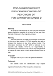
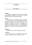
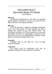
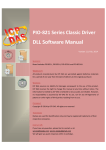
4.3 Flow Diagram for Application
In this section, we will show the operation procedure of PIO-CAN board for
sending and receiving CAN message.
Figure 4.1 presents the “Send CAN
Message” procedure. Figure 4.2 and 4.3 stand for the “receiving CAN Message”
in polling and in interrupt mode, respectively. Users need to follow the operation
principle of PIO-CAN board for correctly and easily send and receive the CAN
message through CAN network. For more detail information, please refer to the
demo programs in section 5.
Start of Application
CAN_ActiveBoard
CAN_Reset
CAN_Init
CAN_Config
CAN_SendMsg
CAN_CloseBoard
End of Application
Figure 4.1 Flow Diagram “Send CAN Massage”
PIO-CAN400/200 User’s Manual
(Ver :1.1 01/27/05)
35
Start of Application
CAN_ActiveBoard
CAN_Reset
CAN_Init
CAN_Config
CAN_RxMsgCount>0?
NO
YES
CAN_ReceiveMsg
CAN_CloseBoard
End of Application
Figure 4.2 Flow Diagram “Receive CAN Massage”
PIO-CAN400/200 User’s Manual
(Ver :1.1 01/27/05)
36
Start of Application
CAN_ActiveBoard
CAN_Reset
CAN_Init
CAN_Config
CAN_EnableRxIrq
CAN_InstallIrq
CAN_RxMsgCount>0?
NO
YES
CAN_ReceiveMsg
CAN_DisableRxIrq
CAN_RemoveIrq
CAN_CloseBoard
End of Application
Figure 4.3 Flow Diagram “Receive CAN Massage with IRQ”
PIO-CAN400/200 User’s Manual
(Ver :1.1 01/27/05)
37
5. Demo Programs for Windows
All of demo programs will not work normally if DLL driver would not be
installed correctly. During the installation process of DLL driver, the installshields will register the correct kernel driver to the operation system and copy
the DLL driver and demo programs to the correct position based on the driver
software package you have selected (Win98,Me,NT,win2000,XP). After driver
installation, the related demo programs and development library and declaration
header files for different development environments are presented as follows.
|--\Demo
|--\BCB3
| |--\CAN.H
|
\PIOCAN.LIB
|
|--\Delphi4
| |--\CAN.PAS
|
|--\VB6
|--\CAN.BAS
Ædemo program
Æ for Borland C++ Builder 3
Æ Header file
Æ Linkage library for BCB
Æ for Delphi 4
Æ Declaration file
Æ for Visual Basic 6
ÆDeclaration file
The list of demo programs:
DEMO1:
DEMO2:
Transmit and receive CAN messages.
Transmit and receive CAN messages with IRQ
PIO-CAN400/200 User’s Manual
(Ver :1.1 01/27/05)
38
A brief introduction of the demo programs
DEMO1:
Demo1 is the example used for starting the PIO-CAN board. This demo
program is designed to send out the CAN message through Port 1 and receive
the CAN message immediately at port 2 in the same PIO-CAN board. Before
exercising this demo, the user needs to finish the CAN median wiring connection
between port 1 and port 2. Based on this demo, the user can key in the CAN
message into the port 1 frame area and then click the “Send” button in order to
send out the CAN message to port 2. If you click the “Receive” button in the
CAN port 2 frame area, the CAN message received by CAN port 2 will be
presented in “TEXT” box. This is shown in the below screenshot. Note that if
port 2 displays a warning message like CAN Data Overrun, then it is an
indication that the un-read messages within the 64 bytes RXFIFO CAN buffer
have been covered by another message. This means that the messages that
are being received from the CAN bus may be in error and/or they may be
missing part of the message. Then the user can click on the “Clear Overrun”
button to clear the RXFIFO buffer overrun status within the CAN controller.
Figure 6.1: The form of demo1 program
PIO-CAN400/200 User’s Manual
(Ver :1.1 01/27/05)
39
DEMO2:
In demo 2, we provide a demonstration on how to send out a CAN message
through port 1 and receive the CAN message in port 2 by means of the interrupt
mode. Contained within this operation, the user can key in the CAN message
into the port 1 frame area and click on the “Send” button to send out the CAN
message. At the same time, the CAN message will be received at port 2 by
means of the interrupt mode. As shown in the following figure, port 2 can
automatically receive the CAN message and store it within the 4K bytes of buffer
software. When the user clicks the “Receive” button, all the messages stored in
the 4K bytes buffer will all be presented in the TEXT edit area, as shown in the
following figure.
Figure 6.2: The form of demo2 program
PIO-CAN400/200 User’s Manual
(Ver :1.1 01/27/05)
40
6. Utility Program for Windows
For PIO_CAN200/CAN400 we also provide a CANbus utility to allow user to
easily and friendly send and receive the CAN messages to and from CAN
network. It can be thought as a useful tool for monitoring or testing CAN
messages on the CAN network, which includes the raw CAN messages,
DeivceNet, CANopen, … and etc. The operation principle will be addressed in
the following sub-section.
(1) CAN Configure
Please select the CAN port and focus on the CAN port configuration area.
According to CAN communication requirement, user need to setup the
Baudrate, acceptance and acceptance mask. And then select transmit or
receive function and finally click enable to open transmit or receive mode of
the relative CAN port。
Figure 6.1 Initial page of the Utility tool
PIO-CAN400/200 User’s Manual
(Ver :1.1 01/27/05)
41
(2) CAN Transmit function
In the Figure 6.2, the CAN Port Transmit mode is opened. User can key in
the CAN message into the framework of the CAN port transmit area and then
click the “send” button to send out the CAN message into the CAN network.
Note that user can key in all of the CAN messages into transmit area and
click the relative “send” button to send out CAN message in sequence. For
example, user can key in the DeviceNet ot CANopen message in the transmit
frame and click the relative “send” button to send out DeviceNet or CANopen
message.
Figure 6.2 Transmit mode
PIO-CAN400/200 User’s Manual
(Ver :1.1 01/27/05)
42
(3) CAN Receive function
Figure 6.3 shows the CAN receive mode. Note that CAN port receive mode is
working on the interrupt receiving mode. Once CAN port receive the CAN
message, it will be shown on the CAN port receive framework. It is especially
valuable for working on CAN bus message monitor analysis.
Figure 6.3 Receive mode
PIO-CAN400/200 User’s Manual
(Ver :1.1 01/27/05)
43
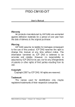
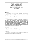
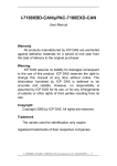
Appendix
Acceptance Filtering
Four 8-bits wide Acceptance Code registers(AC0, AC1, AC2 and AC3) and
Acceptance Mask registers(AM0,AM1,AM2 and AM3) are available for a
versatile filtering of messages. These registers can be used for controlling a
single long filter, as shown in Figure A.1 Which bits of the message are used
for the acceptance filtering, depend on the received frame (Standard or
Extended).
Acceptance Filtering
ACR1
ACR2
ACR3
AMR0 AMR1
AMR2
AMR3
ACR0
CAN Message
Standard Frame
RTR bit
Data 1 Data 2
11 bit Identifier
Bits used for acceptance filtering
Receive
FIFO
Filter
OR
Extended Frame
11 bit Identifier
RTR bit
18 bit Identifier
Bits used for acceptance filtering
Figure A.1 Acceptance Filtering
Example 1:
Suppose a messages with a Standard Frame. The Acceptance Code Registers
(ACRn) and Acceptance Mask Registers (AMRn) contain:
n
0
1 (upper 4 bits)
2
3
ACRn
01XX X010
XXXX
XXXX XXXX XXXX XXXX
AMRn
0011 1000
1111
1111 1111
01xx x010
xxxx
Accepted messages
(ID.28..ID.18 RTR)
1111 1111
(“X”=irrelevant,”x”=don’t care,only the upper 4 bits of ACR1 and AMR1 are used)
At the bit positions containing a ”1” in the Acceptance Mask Registers, any value
PIO-CAN400/200 User’s Manual
(Ver :1.1 01/27/05)
44
is allowed in the composition of the identifier,for the Remote Tranmission
Request bit and for the bits of data byte1 and 2.
Example 2:
Suppose the following 2 messages with a Standard Frame Identifier have to be
accepted without any further decoding of the identifier bits. Data and Remote
Frames have to be received correctly. Data bytes are not involved in the
acceptance filtering.
Message 1: (ID.28) 1011 1100
Message 1: (ID.28) 1111 0100
101 (ID.18)
101 (ID.18)
Using the Single Filter result in accepting four message and not only the request
two:
n
1 (upper 4 bits)
0
2
3
ACRn
1X11 X100
101X
XXXX XXXX XXXX XXXX
AMRn
0100 1000
1111
1111 1111
Accepted messages 1011 0100
(ID.28..ID.18 RTR)
1111 0100
1011 1100
1111 1100
101x
101x
101x
101x
1111 1111
(message 2)
(message 1)
(“X”=irrelevant, ”x”=don’t care, only the upper 4 bits of ACR1 and AMR1 are used)
This result does not meet the request for receiving 2 messages without any
further decoding.
Example 3:
In this example a group of messages with an Extended Frame Identifier are
filtered using a long single acceptance filter.
n
0
1
2
3(upper 6 bits)
ACRn
1011 0100 1011 000X
1100 XXXX
0011 0XXX
AMRn
0000 0000 0000 0001
0000 1111
0000 0111
1011 0100 1011 000x
1100 xxxx
0011 0x
Accepted messages
(ID.28..ID.0 RTR)
(“X”=irrelevant, ”x”=don’t care, only the upper 6 bits of ACR3 and AMR3 are used)
PIO-CAN400/200 User’s Manual
(Ver :1.1 01/27/05)
45