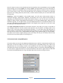
1
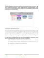
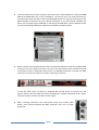
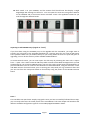
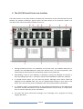
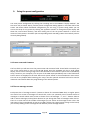
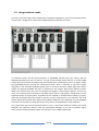
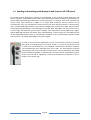
LG-FCB CONTROL CENTER
PATCH EDITOR FOR THE LG-FCB EQUIPPED FCB1010
Contents
1.
Introduction..................................................................................................................................... 3
2.
Quick Start guide ............................................................................................................................. 4
3.
The LG-FCB configuration types ...................................................................................................... 9
3.1 Regular mode ................................................................................................................................ 9
3.2 Direct Select mode ...................................................................................................................... 11
3.3 Direct Select mode with 20 stomps ............................................................................................ 11
3.4 Direct Bank Select mode ............................................................................................................. 12
4.
The LG-FCB Control Center user interface .................................................................................... 13
5.
The LG-FCB Control Center menu structure.................................................................................. 15
5.1 Preferences menu ....................................................................................................................... 15
5.2 File menu ..................................................................................................................................... 15
5.3 Communication setup (MIDI ports)............................................................................................. 16
5.4 Setup assistant............................................................................................................................. 17
5.5 Firmware upgrade ....................................................................................................................... 17
6.
The setup assistant ........................................................................................................................ 18
6.1 LG-FCB operation mode .............................................................................................................. 18
6.2 Switch layout ............................................................................................................................... 18
6.3 MIDI messages............................................................................................................................. 19
7.
Selecting the floorboard configuration type ................................................................................. 21
8.
Doing the global configuration ...................................................................................................... 22
8.1 Expression pedal setups .............................................................................................................. 22
8.2 External expression pedal wiring and calibration ....................................................................... 23
8.3 MIDI-USB routing......................................................................................................................... 24
8.4 Blocking repeated ProgramChange messages ............................................................................ 25
9.
Doing the preset configuration ..................................................................................................... 26
Page 1
9.1 Preset name and Comment......................................................................................................... 26
9.2 The two message streams ........................................................................................................... 26
9.3 MIDI messages............................................................................................................................. 27
9.4 Effect activation commands ........................................................................................................ 28
9.5 Expression pedal commands ....................................................................................................... 28
9.6 Relay commands ......................................................................................................................... 28
10.
Using simulation mode .............................................................................................................. 29
11.
Sending and receiving patch dumps to and from the LG-FCB board ........................................ 30
12.
Monitoring the LG-FCB MIDI output ......................................................................................... 31
Page 2
1. Introduction
The LG-FCB Control Center is an editor for the FCB1010, equipped with the LG-FCB extension board.
More info about the extension board and how to install it can be found in a separate manual. The
current manual covers the Mac and PC editor application which comes with the board.
The application allows you to create and manage LG-FCB setups, download them to the board
through USB, or upload existing setups from LG-FCB board to computer for backup. It also has a builtin simulator which shows you the expected MIDI output for each switch press or pedal movement.
The editor doesn’t send any MIDI messages on its own (it’s not a “virtual floorboard”), but it does
have a window to monitor incoming MIDI messages sent by the LG-FCB board. This way, actual MIDI
output from the floorboard can be easily compared with simulated output from the editor.
Two separate versions of the LG-FCB Control Center have been created, one for Windows, one for
Mac. Each of these versions uses methods native to the operating system for accessing the MIDI
hardware. This turned out to be the most reliable approach for this type of application.
The LG-FCB Control Center is not only a patch editor. It can also be used for upgrading the firmware
on the LG-FCB board. Unlike the original FCB1010, the LG-FCB board stores its firmware in erasable
non-volatile memory. Along with the added USB connection this allows for easy firmware upgrades.
Just load the firmware file in Control Center, and download it to the connected board through USB.
Page 3
2. Quick Start guide
In order to grasp all the details and possibilities of the hardware and editor, it is advised to read this
manual just once from start to finish. However, if you want to get up and running quickly, here are
the basic steps:
1. Connect the included USB cable between LG-FCB board and computer. Power your FCB1010.
2. Upon first connection, allow the computer to initialize the necessary drivers for MIDI-USB
communication. Those drivers are part of the operating system, no driver install is needed.
Windows XP, Vista, 7
On Windows, a series of status balloons will pop up when connecting your LG-FCB for the first time.
They show that new hardware has been detected and drivers are being installed. When ready, the
system will notify you that „your new hardware is installed and ready to use“. This is also visible in
the hardware manager screen of the Windows PC, as a „LittleGiant“ USB Audio device :
Page 4
Mac OSX
On Mac, the MIDI driver install happens silently. After connecting the LG-FCB, it will appear as MIDI
device in MIDI Studio (Applications > Utilities > Audio MIDI Setup > Show MIDI Window) You will
notice 3 built-in bi-directional MIDI-USB ports. Compare it to the 2x4 MidiSport (a dedicated MIDIUSB interface) in the screenshot below.
General remarks about the MIDI-USB ports
After correct initialization of the MIDI-USB connection, 3 extra MIDI ports will be available in all MIDI
aware applications on the computer. Indeed, the built-in MIDI-USB interface on the LG-FCB board has
3 IN and 3 OUT ports, just like all other GORDIUS products. However, only 2 of those ports are
functional on the LG-FCB board. The first port can be used as regular MIDI-USB interface. It can send
MIDI from computer to LG-FCB MIDI connector, or receive MIDI on the LG-FCB MIDI connector and
forward it to any application on the computer. The second port is unused. The third port is dedicated
for communication between LG-FCB Control Center and LG-FCB hardware.
The name used for the LG-FCB MIDI-USB ports can be different depending on used operating system.
Here are a few examples (which may also differ depending on OS language)
-
Win XP : USB Audio device, USB-audio device [2], USB-audio device [3]
-
Win7 : LittleGiant, MIDIIN2 (LittleGiant), MIDIIN3 (LittleGiant), and similar for MIDI OUT ports
-
OSX : LittleGiant Port 1, LittleGiant Port 2, LittleGiant Port 3
Page 5
3. Launch LG-FCB Control Center and go to the menu Setup > Select MIDI ports. Select the third
MIDI IN and MIDI OUT port of the “LittleGiant”, since those ports are used exclusively for
communication with the editor. Select the first MIDI IN port for optional monitoring of the
MIDI messages transmitted by your LG-FCB floorboard. If you had already launched the
editor prior to powering the FCB1010 or connecting the USB cable, click the Refresh button
to have the LittleGiant MIDI ports added to the selection dropdown boxes.
4. Now it’s time to let the editor discover the connected LG-FCB board. Click the big black MIDI
connector icon in the upper left corner. As soon as the editor detects the connected LG-FCB,
its firmware version is displayed instead of the “no FCB1010 connected” message. The MIDI
connector icon now has red pins to indicate a working connection.
In case the editor does not detect an FCB1010 with LG-FCB board, a timeout error will
appear. Please check the USB connection and MIDI port settings mentioned above, power
cycle the LG-FCB, re-launch the editor, and try again.
5. With a working connection, the “send patch dump” and “receive patch
dump” icons (located beneath the MIDI connector icon) are no longer
grayed out.
Page 6
6. Let’s create a very simple setup, just for
testing. Go to Setup > Setup Assistant, and
step through the consecutive pages of the
setup wizard, leaving everything on its
default values. As a result a setup will be
created containing 100 presets, each
sending a single ProgChange command. Of
course, the LG-FCB board will allow you to
create much more extended and complex
setups, but this one is perfect for a first
test. Use File > Save as… to save this newly
generated setup for later reference.
7. Click the “send patch dump” icon (the one with the arrow pointing down). The status bar
should immediately mention “Data transfer completed correctly”. This procedure actually
downloads the setup to the LG-FCB board through USB, and then reads it back again. The
received and transmitted setups are compared byte-by-byte. This way, you can rest assured
that the setup was correctly stored on the LG-FCB board.
8. You can now test the setup by clicking a few footswitches on the FCB1010, and comparing
the transmitted messages with the expected messages shown by the simulator, which is part
of Control Center. The simulation screen is shown as soon as you don’t have the preset
configuration or global configuration pane activated. You can toggle those panes by clicking
the corresponding label in the “display” area of the FCB1010 representation :
9.
In order to enable monitoring click the little black MIDI connector icon in the “MIDI IN
monitor” field. The icon turns red, and the MIDI-USB port is opened for monitoring incoming
MIDI traffic.
Page 7
10. Click switch 1 on your FCB1010, and the monitor field should now also display a single
ProgChange 001 message on channel 1. You can repeat the same test using other switches
on the FCB1010 and in the Control Center simulator screen. The Up/Down buttons let you
scroll through the different banks.
Importing an old FCB1010 setup (regular or “UnO”)
If you have been using the FCB1010 prior to the upgrade with the LG-FCB kit, you might want to
transfer your old setup to the upgraded floorboard as a starting point for your new LG-FCB setup.
That’s possible. Make sure you make a backup of your setup (under the form of a SysEx file) prior to
upgrading. You can do this with any of the available FCB1010 editors.
In LG-FCB Control Center, you can now import the old setup by selecting the menu File > Import
from… > SysEx. This creates a new LG-FCB setup which contains all the MIDI messages which you had
programmed in your previous FCB1010 setup. Just save the newly created setup and download it to
your LG-FCB board. You can now test the floorboard as described above, using the simulator screen
and MIDI monitor of Control Center, prior to testing your setup with your rig connected. After that
you can start from this setup and extend its functionality using the power of the LG-FCB extension
board.
Done !
This concludes our Quick Start step-by-step guide. Once you have successfully followed these steps,
you are ready to discover the actual power of the LG-FCB board. The next chapter will introduce the
different available configuration types for an LG-FCB equipped FCB1010 in detail.
Page 8
3. The LG-FCB configuration types
This chapter covers the main modes of operation for the LG-FCB equipped FCB1010. You may already
be familiar with the two major configuration types available in the stock FCB1010: “normal mode”,
and “Direct Select mode”. In normal mode, you can browse through 10 banks of 10 presets using the
Up/Down switches. In Direct Select mode, you can directly select any out of 100 available presets by
typing its 2-digit preset number.
The LG-FCB board retains those 2 different operation modes, but widely extends them, and also adds
a few extra variations. Normal mode now supports up to 100 banks, and 2 new configuration types
are added (“Direct Select mode with 20 stompboxes” and “Direct Bank Select mode”), which are
explained in the topics below.
Many will know the alternative “UnO” firmware for the FCB1010. One of the major add-ons of that
firmware version was the introduction of a “stompbox mode”. In this mode, 1 row of 5 switches can
behave as 5 stompboxes, with their LEDs showing the current ON/OFF state of an effect. The
remaining 95 regular presets are organized in 19 banks of 5, while the 5 stompboxes are global for all
banks. With the LG-FCB board installed, you no longer need a specific “stompbox mode”, because in
normal mode you can now define any switch in any bank to become a stompbox. This switch
assignment can be global or specific for each bank. There is no more restriction with regards to
number of stompboxes or placement of the stompboxes in each bank. This way the LG-FCB board
allows much more flexibility than the UnO firmware.
3.1 Regular mode
In regular mode, you organize the FCB1010 presets in banks of 10. You can have up to 100 banks in
total. Most of you won’t need 1000 presets, therefore you can specify how many banks you actually
use. When scrolling up or down through those banks using the Up/Down switches, all unused banks
will be skipped. The 2-digit display shows you the index of the current bank, numbered from 00 up to
99.
Page 9
Presets, stomps or momentary effects
Each switch can be configured to work in one of 3 available modes.
Most switches will be used for “regular” presets. When you click the switch, the
corresponding preset is selected (its LED goes ON) and its MIDI messages are
transmitted. (As you will learn later on, a preset can send any number of MIDI
messages both on switch press and/or on switch release.) Important property of a
preset: only one can be active at a time. When you select a second preset, the
previous one will be unselected (its LED will go OFF). You will know this behavior
already from the standard FCB1010.
A switch can also be configured as stompbox. A stompbox is a “toggling” or “twostate” switch, mostly used for activating and deactivating an effect. When you
click a stompbox switch the first time, its LED goes ON, and one or more MIDI
messages are transmitted, which will activate an effect. When you click the same
switch a second time, the LED will go OFF, and a different (set of) MIDI message(s)
is transmitted, which will de-activate the same effect. Obviously, multiple effects
can be active at the same time. As a result several stompbox switch LEDs can be
ON simultaneously, which is not the case when working with regular presets only.
While selecting a preset, stompboxes can be automatically initialized to their ON or OFF state. This
can be configured in the setup of each preset, along with its regular MIDI content, but all of this is
covered in detail in a later chapter.
A momentary effect relates to a stompbox as a momentary switch relates to a
toggle switch. Just like a stomp, a momentary effect switch activates an effect,
with as main difference that the effect is deactivated as soon as you release the
switch, while a stompbox toggles between 2 effect states on each foot click. For
that reason, a momentary effect LED will only be ON for as long as the switch is
being pressed.
Bank layout
The switch layout for each bank can be freely chosen, and can be different for
each bank. With “switch layout” we mean the type of preset linked to each of
the 10 footswitches. You can choose to have all switches act like stompboxes in
one bank, and have 10 regular presets in another bank. You can also define any
of the 10 switches to be “global”: in that case the switch will have the same
functionality in all banks, while you don’t need to program that same function in
each of the banks. Just program the preset (or stompbox or momentary effect)
once, and then with one mouse click specify this switch as “global”, by clicking
its “globe” icon at the bottom.
Page 10
3.2 Direct Select mode
In this configuration the FCB1010 behaves exactly the same as in “Direct Select” mode of the original
Behringer firmware (except that now each preset can send much more messages of course). In order
to select any out of 100 presets, enter its index with 2 foot clicks. The display now shows the preset
number (going from 00 to 99), instead of a bank number. Stompboxes or momentary effects are not
available in this mode, as you need two foot clicks for each preset selection. Since the presets are no
longer organized in banks, the Up / Down switches are no longer needed for browsing through the
banks. The Up switch now controls the “SWITCH1” relay output of the FCB1010, while the Down
switch controls the “SWITCH2” relay output.
3.3 Direct Select mode with 20 stomps
As mentioned above, in “Direct Select” mode you don’t have any stompboxes available. For that
reason, a special extension to the Direct Select mode has been introduced, which adds direct access
to 2 banks of 10 stompboxes. The “Up” switch can be used to toggle between both stompbox banks.
A click on the “Down” switch indicates that you want to select a preset using the known “Direct
Select” mode. So you click “Down”, followed by 2 digits, in order to select any out of 100 available
Page 11
presets. Three clicks are required to select any preset, while a single click on switch 1-10 toggles the
corresponding stompbox, and a click on the “Up” switch toggles between the 2 stompbox banks.
As before, the display shows the index of the currently active preset. Apart from that,
a “+” sign is shown next to the preset index when the second stompbox bank is
currently active.
3.4 Direct Bank Select mode
If you want to use a large number of banks in a flexible way, you might consider using the Direct Bank
Select mode. We intentionally show the same picture here as in the previous topic about regular
mode. Indeed, Direct Bank Select mode gives you the same possibilities as regular mode, only the
way you select a bank is different. In regular mode, you browse through the banks using the Up and
Down switches, which may take some time if you want to scroll from bank 1 to bank 50. In Direct
Bank Select mode, you directly select a bank by clicking “Down” followed by the 2 bank index digits.
This way you can reach any out of 100 banks with 3 clicks. The display again shows you the currently
selected bank index. After selecting a bank, you can access the 10 presets within that bank simply by
clicking the corresponding footswitch. Just like in regular mode, each bank can contain any mix of
presets, stompboxes, or momentary effects, and each switch can be defined to be global or bank
specific. On top of this, one “direct bank” is available, which is always one single click away: the “Up”
switch lets you toggle between the currently active bank and this “direct bank”.
The display shows “db” whenever the direct bank is active. Even if some of the
switches are defined as “global”, you are able to give them a different function when
the “direct bank” is active.
Page 12
4. The LG-FCB Control Center user interface
The editor consists of one main window. All frequently used actions can be accessed from that main
window, the number of different popup menus has been limited to the minimum. Below is an
overview of the main functionality and how to access it:
1. Clicking the MIDI connector icon establishes a connection with your FCB1010. Before this is
possible, the used MIDI-USB ports need to be selected. This is a one-time operation, after
initial setup the chosen ports are permanently stored as user preference.
2. Downloading a setup to your FCB1010, or uploading a setup from FCB1010 to computer, is
done by clicking these icons. A connection needs to be established to enable the 2 buttons.
3. In LG-FCB Control Center you can name all presets. Although those names cannot be
displayed on the FCB1010 itself, they are very helpful while working on your setup in the
editor. The name of each preset is displayed in the user interface above its footswitch.
4. In “simulation mode”, the footswitches on the graphical representation of the FCB1010 can
be used to simulate the behavior of your floorboard with the current setup. In “setup mode”
they are used to select the preset to be edited.
5. The status bar shows informative messages, error messages, and a progress bar during
lengthy operations.
Page 13
6. In simulation mode, clicking a preset switch causes all MIDI messages programmed for that
preset to be listed in this field.
7. These 2 fields show you the transmitted MIDI messages when simulating a movement of
each of the 2 expression pedals.
8. A MIDI IN monitor field allows you to inspect the actual MIDI output of your FCB1010. It is
placed next to the simulation output, so you can easily verify your programming by
comparing expected output and actual output.
9. Clicking this MIDI connector icon toggles the MIDI monitor function on and off.
10. In simulator mode these small LEDs show if an expression pedal is currently enabled, just like
on the real floorboard.
11. Two vertical sliders can be used to simulate the movement of the 2 expression pedals.
12. While in simulation mode, the 7-segment display behaves exactly the same way as the
display of the real pedal. In setup mode it shows the currently selected bank. You can edit
the content of each of the 10 presets in that selected bank.
13. As soon as you click the “Connect” button (see 1.) and an LG-FCB board is detected, the LGFCB firmware version is displayed here.
14. The “PRESET CONFIGURATION” and “GLOBAL CONFIGURATION” labels on the FCB1010
window can be clicked to select the current mode. You can toggle between preset config and
global config mode, or if none of both are activated, the software runs in simulator mode.
15. In simulator mode these small LEDs show whether the 2 relay outputs are currently closed or
opened, just like on the real floorboard.
16. Click this icon in order to select the floorboard “operation mode”: regular mode, Direct Select
mode, Direct Select with 20 stomps, or Direct Bank Select. Those different modes have been
covered in detail in a previous chapter.
Page 14
5. The LG-FCB Control Center menu structure
There are only a few menus, since most functionality is directly accessible from the main window.
Overview of all menus on Mac
The menu items are identical on the Windows version, the location is slightly different, in accordance
to the OS specific design guidelines.
5.1 Preferences menu
One user setting is available in the small preferences menu :
you can choose to display the ProgramChange messages using a range from 000 to 127, or from 001
to 128. Regardless of this setting, a MIDI message always uses a value range of 000-127. However, in
the case of ProgramChange messages, many will find it more intuitive to display this as a value going
from 001 to 128, because that’s how many manufacturers number the presets in their gear.
5.2 File menu
The file menu contains the standard options to open or save a setup, or to create a new one. A list of
recently opened files is available for quick access.
Two ControlCenter specific options require some more explanation : Import from Text or SysEx, and
Export to Text or Sysex.
Page 15
Since all setups are sent to the LG-FCB board and received from the LG-FCB board as one long MIDI
SysEx message, you can also export your setup to SysEx. This would allow you (if ever necessary) to
send your setup to the FCB1010 using any third party SysEx Librarian. However, keep in mind that
part of your setup is never sent to the LG-FCB board, and is therefore not stored in the exported
SysEx file: we’re talking about all preset names, and the comments which you can enter about each
of the presets.
Importing a setup from SysEx is also possible. Again, you will never restore preset names or
comments through a SysEx import. However, this function can be very useful at the moment of
upgrading your FCB1010 with the LG-FCB board. Before doing so, you can save your current setup
(regular or UnO) to SysEx, using FCB/UnO ControlCenter or any other FCB1010 editor. After doing the
hardware upgrade, you can again import your old FCB1010 SysEx file into LG-FCB ControlCenter, and
start your extended setup from this imported file. This will give you a jump start, as you won’t need
to create your new setup from scratch.
The import from/export to Text are convenience functions. They allow you to get an overview of
your complete setup as a text file, which can be opened in any text editor. You might prefer a text
editor to fill in the preset names and optional comments, or to do some quick copy-and-paste of
preset contents. Just be aware that the supported text format is very strict, and therefore editing the
text can be error prone, since a malformatted text might not get imported again in Control Center.
Just make sure to create a regular backup of your text setup, this way you can always take one step
back and correct possible typing or formatting errors.
5.3 Communication setup (MIDI ports)
This menu allows you to select the MIDI IN and MIDI OUT port used for communication with the LGFCB board, and also the MIDI port used for monitoring the LG-FCB MIDI output. This needs to be
specified only once. The setting is stored as user preference for later reuse. When plugging in the
USB cable after launch of ControlCenter, use the Refresh button to refresh the detected MIDI ports.
(In some cases it might be necessary to close ControlCenter and launch it again with the USB cable
connected and FCB1010 powered, to get the MIDI-USB communication working correctly )
Page 16
As mentioned in the dialog, use LittleGiant port 3 for communication between ControlCenter and LGFCB, and use LittleGiant port 1 for monitoring the LG-FCB output. Also, make sure that your setup has
USB output enabled (this is the case by default). As explained in detail below, one of the global
settings is the choice of MIDI output routing: MIDI can be sent to the MIDI connector, to the USB
connector, or to both. Make sure routing to the USB connector is enabled if you want to monitor the
LG-FCB MIDI traffic in ControlCenter.
5.4 Setup assistant
Use of the setup assistant is covered in detail in the next chapter. It allows you to create a new setup
with just a few mouse clicks.
5.5 Firmware upgrade
While the original FCB1010 firmware was stored in a one-time-programmable memory chip, the LGFCB board uses an electrically erasable chip for firmware storage. As a result, firmware upgrades can
be done very easily through USB, without the need for disassembling the unit, as was previously the
case. Simply select the firmware file, which should have the file extension “.lgf”, and it will be
downloaded to your LG-FCB board. This menu option will only be enabled after a connection has
been established between Control Center and LG-FCB (by clicking the big MIDI Connector icon in the
main screen).
Page 17
6. The setup assistant
The setup assistant allows you to create a new LG-FCB setup in just a few mouse clicks. Inevitably,
the resulting setup will use only a very small subset of the possibilities of the LG-FCB board. But it can
serve as the starting point for building a much more extended setup, tuned to your needs. Using the
setup assistant can also be a good way to experiment with the different LG-FCB operation modes and
test things out with a few quickly generated sample setups.
6.1 LG-FCB operation mode
The first step of the wizard lets you select one of the available operation modes or configurations.
Those configurations have been discussed in great detail in chapter 3.
6.2 Switch layout
Page 18
The next step lets you define the switch layout of the banks: which switches will be used for regular
presets, which for stompboxes, and which for momentary effects. This step is only available for
regular mode or direct bank select mode, since the other operation modes have a fixed switch layout
of 10 regular presets per bank. The wizard allows you to define one single switch layout, which will
be applied to all banks. Be aware that an LG-FCB setup offers much more flexibility, with the
possibility to define a different layout in each bank, but for the sake of simplicity the wizard creates
the same layout in all banks. A further simplification limits the choice for each switch to a preset, a
bank specific stompbox, a global stompbox, or a global momentary effect, although in reality each
switch can be defined as global or non-global, whether it is a preset switch, stompbox, or momentary
effect.
6.3 MIDI messages
The next and final step gives you again a few very limited choices, in contradiction to the full
flexibility which an LG-FCB setup actually offers. You can specify which MIDI channel will be used for
all auto-generated MIDI messages, and you can specify a ControlChange number for each of the 2
expression pedals. With this limited information, a setup will be created with following preset
contents :
-
Each regular preset contains a single ProgramChange message, with increasing ProgChange
number, used for selecting patches or sounds.
-
Each stompbox and momentary effect contains 2 ControlChange messages, one to activate
and effect, and one to deactivate the same effect. Again increasing ControlChange numbers
are used for each of the 2-state or momentary effects.
-
A “global” expression pedal setup is linked to each of the 2 expression pedals. This means
that the 2 expression pedals (if activated in this wizard step) will have the same function for
all presets (see a later chapter about global configuration to learn more about global
expression pedal setups). When moved, the pedals will send a continuous stream of ControlChange messages with the given ControlChange number.
Page 19
After running through those 2 or 3 steps, a setup is created, which you can immediately download to
your LG-FCB board and test. You can also use the built-in simulator to see how exactly the setup will
behave. All of this is explained in full detail in a next chapter. Don’t forget to save your newly created
setup to file.
Once you have verified how the demo setup behaves, you can start building your final setup, either
starting from the auto-generated wizard setup, or by starting from scratch (just click “File > New” to
clear the current setup and start with a new blank setup).
The next chapters guide you through the different steps of manually creating a setup, testing it with
the simulator, downloading it to the LG-FCB board, and testing it “in real life”. Let’s move on!
Page 20
7. Selecting the floorboard configuration type
The different available configuration types have been explained in detail in chapter 3. The preferred
configuration type can be selected as a first step in the setup assistant, as shown in previous chapter.
However you can also choose one of the configuration types at any time by clicking the small
floorboard icon indicated above. This opens following dialog:
Choose one of the configurations, and the lower part of the dialog will give you some more info
about that selected mode.
Page 21
8. Doing the global configuration
You enter global configuration mode by clicking the according text in the FCB1010 “display window”.
The text turns red (as shown above), and the global configuration dialog appears in the lower half of
the screen.
8.1 Expression pedal setups
Both expression pedals of the FCB1010 can be programmed to send any ControlChange message.
The LG-FCB kit also comes with an optional “expression pedal module”, which replaces the original
relay output jacks with 2 stereo input jacks for external expression pedals. If you have installed this
optional module, you can program the 2 external expression pedals, labeled “expr.pedal 1” and
“expr.pedal 2” in the editor, additionally to the 2 internal expression pedals, which are labeled
“expr.pedal A” and “expr.pedal B”.
All expression pedals can be programmed to send
ControlChange messages with a given CC number and with
CC value within a given range. This programming can be
global, which means it is not depending on the currently
selected preset, or it can be different for each preset, as
you will learn in a later chapter.
An expression pedal setup defines the expression pedal
behavior: MIDI channel, CC number, CC value range
between heel down and tip down positions. For ease of
use each setup can be given a meaningful name (doubleclick the name to edit it). You can specify an inverted
sweep by choosing a bigger value at heel position and smaller value at tip position.
Page 22
The default behavior of each expression pedal is
defined by adding a pedal setup to its global
assignment list. Each assignment list can contain
multiple pedal setups. This way a single pedal might
for instance send volume commands on multiple MIDI
channels, or do a fader effect between 2 sounds by
combining a simultaneous rising and falling volume
sweep.
8.2 External expression pedal wiring and calibration
Obviously this part of the global setup is relevant only if you have installed the optional external
expression pedal module. The described calibration procedure covers the external expr.pedal inputs
only, calibration of the FCB1010 internal expr.pedals is described in the Behringer manual.
Calibration
The LG-FCB kit is shipped with pre-calibrated expression pedal inputs. However, a slight adjustment
might be needed when connecting your own expression pedal for the first time. A wrongly calibrated
unit will never reach the end values of the programmed range, or it will show excessive “dead zones”
at both ends of the range.
Before clicking the “Calibrate” button, there are a number of things to take care of first.
-
The USB port for MIDI monitoring needs to be selected correctly. See menu “Setup > Select
MIDI ports > MIDI IN port for monitoring”. Make sure this is set to “LittleGiant”.
-
The FCB1010 needs to send its messages to this USB port, and not only to the MIDI OUT port.
Activate this in the routing panel of the global configuration, as shown in topic 8.3 below.
-
A unique expression pedal setup needs to be assigned to each expr.pedal. Each of these
setups needs to use a unique CC number. This is necessary for ControlCenter to link the
incoming ContrChange messages to the correct expression pedal. Use the global expr.pedal
assignment setup described in previous topic to assign the necessary expr.pedal setups. After
calibration, you can again remove those setups or adapt them to your needs.
-
It’s advised to program the expr.pedal setups with a “full range” during calibration, that is
with Heel value set to 0 and Tip value set to 127. Programming a limited range at this stage
might confuse you during calibration, since you would never reach the limit values of 0 / 127.
Once you have met all of the points above, and you have downloaded the updated setup to your LGFCB board, you are ready to proceed with the actual calibration. When you click the Calibrate button,
ControlCenter will show you the transmitted ControlChange values for each of the 2 external
expr.pedals. Do a full sweep with both pedals, and check if the full range of 0-127 is being monitored.
Page 23
If the value of 0 is never reached in heel down position, you will need to increase the ADC minimum
value for that pedal. If however you have a large dead zone in the heel region (that is: the value of 0
is reached long before the pedal is in full heel down position), you will need to decrease the ADC
minimum value. After changing the value, click the “Update” button to send the changes to the LGFCB board, and test again. You might need a few iterations to find the optimal setting.
The same applies to the tip position of the expression pedal: if you never reach the maximum value
of 127, decrease the ADC maximum value. If you reach value 127 too soon, increase the ADC
maximum value.
Wiring
Expression pedals come in 2 “flavors”, sometimes referred to as “Roland
type” or “Yamaha type” pedals. The Roland type pedals have the wiper
of the internal potentiometer wired to the tip of the stereo jack. The
Yamaha type pedals have the wiper wired to the ring of the stereo jack.
The optional expression pedal board has the necessary
electronics on board to support any of both wirings. In
the global configuration, choose the wiring of your
expression pedal, and send this setting to the LG-FCB
board by downloading the setup. If you are not sure
about which setting to choose, calibrate your pedal as described above, and then have a close look at
the expression pedal output. Even when choosing the incorrect wiring option, you will still be able to
have your expression pedal send the full MIDI range. However, you will notice a very “non-linear”
sweep: CC values will rise very quickly from 0 to 80, and after that they will go much slower from 80
to 127. Correcting the wiring setting will result in a smooth and linear sweep from 0 to 127. When in
doubt, just try out both settings to see the difference.
You can also watch a small YouTube video covering this topic: go to YouTube and search for “lg-fcb
tutorial 5”
8.3 MIDI-USB routing
The MIDI messages sent by the LG-FCB board can be
routed to the MIDI connector, to the USB connector or
both. The same applies to the incoming MIDI, which can
also be routed to each of both ports (MIDI and/or USB)
Page 24
8.4 Blocking repeated ProgramChange messages
It is possible to block “repeated” ProgramChange messages. In that case, a ProgramChange message
with the same MIDI channel and PC number will never be sent twice in a row.
As you will see later on, a preset can not only contain a PC number for sound selection, but also
effect activation messages to turn on certain effects. If you activate or deactivate those effects
during playing (using dedicated stompboxes), you might want to return to the original effect state for
the current sound, by clicking the same preset switch again. This is the most common case where you
might want to use above setting to avoid sending the same PC message to the sound module again,
which with some sound modules would result in a short drop out of the sound.
Page 25
9. Doing the preset configuration
You enter preset configuration by clicking the according text in the FCB1010 “display window”. The
text turns red (as shown above), and the preset configuration dialog appears in the lower half of the
screen. No matter which floorboard configuration you are using, in preset config mode you can
access the setup for any preset by clicking the up/down switches to change bank (the display will
show the current bank number), and then clicking one of the ten preset switches to access the
content of each preset in that bank (the corresponding switch LED will go ON to show which preset is
currently being edited).
9.1 Preset name and Comment
The first fields you will notice are the preset name and comment fields. These fields are actually not
part of the setup which is sent to the LG-FCB board. Since the FCB1010 only has a small 2-digit
display, there’s no use storing a large text in the floorboard. The text data is part of the LG-FCB binary
setup, stored on your computer, but not part of the MIDi SysEx patchdump sent to the floorboard.
Preset names are displayed at all time above each preset switch in the ControlCenter main screen.
This can be very helpful while browsing your setup. Also the optional comment field can be used to
memorize some details about the programming of the selected preset.
9.2 The two message streams
Each preset has 2 “message streams” (streams or bursts of transmitted MIDI data). A regular preset
can send a first stream of messages on switch click, and it can optionally send a second stream of
messages on switch release. Each stream is shown as a list of messages. “+” and “-“ buttons allow to
add or remove messages, and up/down buttons let you change the order of messages within the list.
There is no strict limit on the number of messages you can add to such message stream. This is the
real power of the LG-FCB board: as long as you didn’t fill the (very large) preset storage on the board,
you can keep adding various messages to the different preset message streams.
Page 26
Chapter 3.1 already explained the 3 different supported preset types: regular presets, stompboxes
and momentary effects. Also with regards to the 2 message streams, those preset types behave
differently. Both regular presets and momentary effects can send a first message stream on switch
press and a second stream on switch release. Stompboxes on the other hand act as toggling switches.
The first message stream is transmitted when doing a first foot click, which activates the stompbox
(causing its LED to go ON). The second message stream is transmitted when the stompbox switch is
clicked again to deactivate it (causing its LED to go OFF). Stompboxes never send MIDI messages on
switch release.
The message streams contain all MIDI messages to be
transmitted by the preset, but they can contain more
than that. Next topics give an overview of the different
supported commands.
9.3 MIDI messages
When you click the “+” button of one of the 2
message streams, a ProgChange MIDI message
is added to the stream. After that you can edit
its contents in the right side content panel.
The first radio button indicates that we want to add a MIDI message to the stream. The selection
fields below that allow you to add any type of MIDI message, on any MIDI channel. Indeed, if you
click the dropdown box in the setup panel, you will see that you can choose from all message types
defined in the MIDI standard. Also, you can combine any number of different MIDI messages within
the same message stream. This is a huge extension of the functionality of the original FCB1010,
which only allowed a fixed number of messages per preset, limited to ProgChange, ControlChange or
NoteOn/NoteOff, and each sent on their “global” MIDI channel, which needed to be the same for all
presets.
Another option in the setup panel is the possibility to add a programmable delay before sending the
MIDI message. This is a powerful option which can be very useful for certain MIDI controlled amps or
effects processors. Some of those devices need some time after receiving a ProgChange command
for loading a new sound. If you want to select a sound and activate a few effects with one single click
(which is perfectly possible with the LG-FCB board), you might need to add a small delay between the
ProgChange command and the effect activation ControlChange commands.
Another fun application for this programmable delay feature is when using it in NoteOn/NoteOff
messages. It allows you to play certain chords or note sequences with programmable note lengths,
triggered by a single foot click.
Page 27
9.4 Effect activation commands
A second command type which can be part of a
messagestream is the stompbox activation command.
After creating some stompboxes to activate certain
effects, you can automatically turn those effect stomps
on or off when selecting a preset.
To do so, you add a “stompbox activation” command at any place in the message stream of the
preset. In the command setup panel, select one of the stompboxes which are part of your setup, and
specify if the effect needs to be activated or deactivated. Optionally you can add a delay before the
activation of the effect (it is advised not to use any delay unless your gear really needs it to work
reliably)
When a preset is selected and the “stompbox activation” command is fired, two things happen. The
MIDI messages linked to the ON or OFF state of that stompbox are transmitted (those MIDI messages
are specified in the content of the stompbox itself). Secondly, if the stompbox is located in the same
bank as the preset, the LED of that specific stompbox will be turned ON or OFF. If the stompbox is
located in a different bank, you will see its correct LED state when scrolling to that bank.
Next to setting effect states for a regular preset, you can also use effect activation commands in the
message stream of a stompbox. This can be useful for instance if you want to automatically turn an
effect OFF as soon as another effect is switched ON, thus creating groups of “mutually exclusive”
effects.
9.5 Expression pedal commands
The third command type is the expression pedal
command. With this command you can make the
expression pedal behavior preset dependent. Choose
one of the expression pedal setups which are part of
the global setup (see chapter 8.1) and link it to internal expr.pedal A or B of your FCB1010, or (in case
you have installed the optional expr.pedal input board) to external expr.pedal 1 or 2. As soon as this
preset is selected, the specified expr.pedal setup will be activated. You can also disable a pedal by
selecting “[none]” as expression pedal setup.
9.6 Relay commands
The last command type is the relay command. The
FCB1010 has 2 relay outputs labeled “SWITCH 1” and
“SWITCH 2” (we prefer to use the term “relay” in order
to avoid confusion when talking about foot switches).
With a relay command you can close or open each of the 2 relay outputs when selecting a preset or
effect. This feature can be used to control amps which are not MIDI controllable. A preset can switch
channels on such an amplifier and at the same time send some MIDI commands to other devices.
Page 28
10. Using simulation mode
As soon as you leave both preset configuration and global configuration, you are in simulation mode.
Just click the “configuration” labels in the FCB1010 window until both are white.
In simulation mode, click the preset switches or UP/DOWN switches with your mouse, and the
FCB1010 will behave just like “in real life”. The LED of the selected preset will turn on, and the MIDI
output field will show the messages being transmitted when selecting that preset. In regular mode,
the UP/DOWN switches activate the next/previous bank, which is reflected in the bank number
displayed on the simulated FCB1010 display. Also in the other operation modes (like Direct Select
mode) the depicted FCB1010 will react as described in the chapter about those different modes.
When your mouse hovers over one of the expression pedals, a vertical slider appears, and you can
move it to simulate pedal movement. The MIDI output field for expr.pedal A and B show you the
expected output for those pedals. As pedals can be enabled or disabled when selecting a preset,
check the small LEDs above the pedals to see their current state (active or not). Similarly, the small
yellow LEDs at the left side of the display area (labeled “SWITCH1” and “SWITCH2” on your FCB1010)
are used in the simulator to show the current relay status: closed (LED ON) or open (LED OFF).
Let’s repeat here that the LG-FCB Control Center is not a “virtual FCB” which can replace your actual
FCB1010. The application doesn’t send any actual MIDI messages; it just has a simulator engine
which shows the expected MIDI output as text entries in the 3 MIDI output fields
Page 29
11. Sending and receiving patch dumps to and from the LG-FCB board
For sending a patch dump from computer to LG-FCB board, or for receiving a patch dump from LGFCB to computer, a MIDI data stream needs to be transferred between computer and floorboard. A
specific MIDI command type called SysEx (“System Exclusive”) is used for that. Such command can
contain much more data than a regular 2- or 3-byte MIDI command, and the content can be
formatted the way any manufacturer prefers (hence the name System Exclusive). Unfortunately,
many cheaper MIDI-USB interfaces are primarily designed for “mainstream” MIDI communication
(forwarding ProgramChanges, ControlChanges and synth Note messages) and don’t work well to
transfer large manufacturer specific SysEx messages. This dependency of the FCB1010 on higherquality MIDI-USB interfaces has always been a disadvantage. Luckily enough, the LG-FCB board has
its own MIDI-USB interface built in, and therefore reliability of the communication between board
and computer is no longer depending on any external gear.
In order to avoid too much duplication of info, we would like to refer to the Quick
Start guide at the beginning of this manual. Topics 3, 4, and 5 on p.6 show you how
to select the correct MIDI ports and establish communication between computer
and LG-FCB board. After following those short steps, the ControlCenter interface
should display the current LG-FCB firmware version, and the download and upload
buttons should be enabled, as depicted here. At that moment, downloading a patch
dump to the LG-FCB or uploading a setup from floorboard to computer is just a
matter of one mouse click.
Page 30
12. Monitoring the LG-FCB MIDI output
In chapter 10, we explained how you can simulate the MIDI output of your LG-FCB equipped
FCB1010 using the Control Center user interface. In chapter 11, we briefly revisited the steps
required to download your LG-FCB setup to the floorboard. Now you are ready to check the
actual MIDI output of your programmed FCB1010 and compare it with the simulation.
A first requirement is that you have selected the correct MIDI-USB port for monitoring. As
shown in step 3 of the Quick Start guide (chapter 2), you need to select the port labeled
“LittleGiant port 1” for monitoring purposes (as mentioned on p.5, port name can be slightly
different, depending on operating system).
A second requirement is that your LG-FCB board needs to be programmed to forward all its
MIDI to its USB port, and not only to its MIDI OUT port. This routing setup is part of the
global configuration, which is explained in chapter 8. If routing to USB was not enabled yet,
enable it now and don’t forget to save the change and download the updated setup to your
floorboard.
Now click the small black MIDI connector icon in the “MIDI IN monitor” field. The icon will
turn red (as depicted below) and the MIDI IN monitor field will be enabled. As soon as you
click a switch on your floorboard or rock an expression pedal, the transmitted MIDI
messages will appear in the monitor field. You can simulate the same switch clicks in the
Control Center user interface, and do a side-by-side comparison between the simulated
output and the actual floorboard output. Whenever you want to clear the monitor field, just
toggle the small MIDI connector icon to disable/enable monitoring. This will also clear the
displayed data.
Page 31
That’s it folks! Have fun with your LG-FCB equipped FCB1010 and LG-FCB Control Center!
Page 32