1
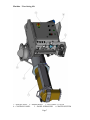
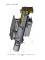
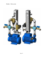
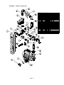
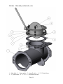
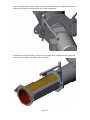
D-35 Silo mixer
User Manual
Electric
#60010166 D-35 SILO-MIX - 220V 1 phase
#60010167 D-35 CONT-MIX - 220V 1 phase
#60010178 D-35 SILO-MIX - 220V 3 phase
#60010179 D-35 CONT-MIX - 220V 3 phase
Page 1
Dear Customer,
Before starting this machine please complete the following;
Machine Date of purchase…………………………………..
Machine serial number………………………………………
Please read the following information contained within this manual and fully familiarize
yourself with the equipment.
Page 2
Contents
Page
Section 1 - General Safety information.........................................................................4
Danger ........................................................................................................................4
Section 2 - Machine Description ...................................................................................5
Function......................................................................................................................5
Machine illustrations..................................................................................................6
Machine – silo mounted shown...............................................................................6
Machine - View facing left ......................................................................................7
Machine - View facing right ...................................................................................8
Machine – control panel .........................................................................................9
Machine – Water system.......................................................................................10
Machine – Water system-cont ..............................................................................11
Machine - Nozzle Assembly ..................................................................................12
Machine – Drive line, feed liner and feed screw ..................................................13
Machine – Main body and butterfly valve ...........................................................14
Section 3 – Unpacking and Machine assembly...........................................................15
Section 4 – Machine set up and operation ..................................................................21
Machine control panel operation - explained..........................................................21
Electrical connections, and first start up.................................................................22
General operation ....................................................................................................23
Start up..................................................................................................................23
Shut down..............................................................................................................23
Operational notes .....................................................................................................24
Section 6 – Maintenance..............................................................................................25
General notes............................................................................................................25
Feed screw removal..................................................................................................26
Mixing shaft separation ...........................................................................................27
Wear parts................................................................................................................28
LIMITED WARRANTY POLICY............................................................................29
Page 3
Section 1 - General Safety information
Danger
Follow these instructions very carefully, in order to avoid injury to yourself or others.
Electrically powered machine.
Always ensure that all power to the machine has been turned off and isolated before
ANY maintenance / repair work is carried out on the machine.
Ensure that all guards are correctly fitted before starting or attempting to operate the
machine.
Ensure that all fasteners are present and correctly fitted before attempting to start or
operate the machine.
Ensure that the nozzle unit is correctly fastened to the front of the mixer unit of the
machine, and free of damage before attempting to start or operate the machine.
Ensure that the breaker assembly is free to rotate within the nozzle assembly prior to
starting the machine.
The D-35 continuous mixer unit can produce high torques and can use high voltages.
Care must be taken by authorized persons when using and working with this machine.
Page 4
Section 2 - Machine Description
Function
The continuous mixer uses pre blended material, in either silo fed or pre-bagged form,
that is poured into the hopper, that then discharges into the nozzle and mixes it with
water, to provide a usable mixture at its outlet.
The machine has a drive motor, which turns a drive shaft within a material hopper that in
turn rotates a helical feed screw, in turn rotating a mixing shaft. The combination of these
shafts and mixing components move material from the hopper through to the mixing
nozzle, that with the addition of an adjustable water control that hydrates the mixture to
the desired level. The mixing tines in the nozzle tube, mix and shear the material so that
once it emerges from the discharge aperture, the mixture is correctly mixed and sheared
ready for use or for pumping to the application.
The machine is driven by an electric motor powered by 3 phase voltage, via an electronic
variable speed inverter supplied by two phase 208-240 VAC 50/60Hz, alternately 208240 VAC 3 Phase or 440/480 VAC 3phase. Input power.
The inverter control box allows the user to adjust the speed of rotation in three preset
steps (these step points are factory set but can be adjusted to suit the individuals
requirements – please consult Machine Technologies for more information) combined
with the volumetric displacement per rev of the feed screw, to provide the required
“flow” of material. The control box also contains controls for the water system that
operates when the unit is started in the “feed” direction. If the unit is reversed for any
reason the water feed will turn off, and then turn back on once the reverse knob is
released.
The water control system contains a water pump, pressure regulator, a control valve,
pressure switch and a visual water flow meter. The flow of water from the meter into the
mixing nozzle is adjustable via the control knob at the meters base. Turning clockwise
slows the flow rate, counter clockwise increases the flow.
A vibrator power feed is provided on the side of the control panel to connect to a vibrator
control box and vibrator, designed to be fitted to a silo or hopper needing vibration
The difference between the machines is primarily the input voltage / phase, but
additionally, different dosing screws are available allowing an additional variation of
material output, for the same pre-set speeds.
Page 5
Machine illustrations
Machine – silo mounted shown.
Page 6
Machine - View facing left
1 – NOZZLE ASSY 2 – MIXER BODY 3 – BUTTERFLY VALVE
4 – CONTROL PANEL
5 – PANEL SURROUND
6- WATER SYSTEM
Page 7
Machine - View facing right
7- MOTOR GEARBOX.
8 – MOTOR HINGE 9 – ASSEMBLY WEDGE.
Page 8
Machine – control panel
The base frame can be re-configured to have the wheels, axle etc. located at the opposite
end of the unit, with the handle thus also being mirrored. The control panel assembly on
handle assembly can be moved, by pulling the pins keeping the handle assembly in place
in the frame, then sliding the handle out, allowing access to the control box itself
1 – Base frame
5 – Wheel / Tire
2 – Handle
3 – Axle lock
Page 9
4 – Axle
Machine – Water system
Page 10
Machine – Water system-cont
Page 11
Machine - Nozzle Assembly
1 – MIXING TUBE ASSY 2 – MIXING SHAFT ASSY
3 – MIXING TUBE DISCHARGE ASSY 4 – LOCKING WEDGE (4)
Page 12
Machine – Drive line, feed liner and feed screw
1 – Motor gearbox, 2 – Feed screw, 3 - Feed liner, 4 – Liner retainer, 5 –pin & clip
6 – Motor hinge plate, 7 – locking wedge, 8 – Motor adapter/breather, 9 – poly seal
10 – Clamp plate, 11 – Drive Auger, 12 – fixing bolt (4)
Page 13
Machine – Main body and butterfly valve
1 – Main body, 2 – flange gasket, 3 – butterfly valve, 4 – ½”-13 thin locknut,
5 – ½” plain washer, 6 – ½”-13 x 1 ½” full thread hex bolt
Page 14
Section 3 – Unpacking and Machine assembly
Typical pallet packaging
Upon, delivery remove the contents of the shipment and assemble per the previous
illustrations.
Page 15
Assemble the main body, inclusive of the feed liner and the butterfly valve, to the lower
flange of your silo. The use of a fork lift to help in this process is recommended. Ensure
that the operating lever of the butterfly valve can rotate throughout its range without
hitting the silo base, the control panel assembly the main body, or any other fixed item.
NOTE, that the swivel ring side of the valve must face the main body of the mixer, or the
flap disc will not open fully. The disc pivot is off center in the butterfly valve, the pivot
should be closer to the silo side and further from the main body of the mixer
Once the main body and the butterfly valve have been secured using the 16 bolts, washers
and nuts, then the motor assembly must be affixed to the pivot block using the hinge pin.
Page 16
Once the motor assembly has been fitted and the pivot pin secured, it might be necessary
to adjust the eye bolts on the motor mounting plate to ensure that the plate closes snugly
against the open end of the main body
When closing the motor plate you will have to support the end of the drive shaft and
rotating to align correctly with the drive auger
Page 17
Once closed then the locking wedge must be inserted and hammered lightly into place to
secure the assembly and maintain the drive shaft engagement.
Assemble the nozzle assembly to the front of the main body, and hammer into place the
two wedges to hold the assembly to the main body
Page 18
Insert the mixing shaft into the nozzle, rotating the shaft as it is slid towards the main
body.
The tapered end of the shaft will locate into the hole in the end of the feed shaft and
eventually due to the rotation, the drive pin will align with the slot in the feed shaft and
rotation will become a lot harder, in turn actually turning the motor shaft.
Assemble the nozzle assembly to the front of the mixing tube and secure with the
wedges. Ensure that the mixing shaft end locates into the plastic bushing in the end of the
nozzle assembly.
Page 19
Hang the main control panel assembly on the side of the main body, by engaging the
“hooks” into the slit cut outs on the top of the main body and then align and pin the rear
bracket with the corresponding feature on the main body.
Insert the water feed pipe into the opening in the main body molding of the feed liner
Page 20
Section 4 – Machine set up and operation
Machine control panel operation - explained
The electronic Drive module comprises of a variable speed frequency inverter, allowing
the use of 220VAC two or three phase to run the high torque 3 Phase gear motor. The
unit is rated at 4KW providing plenty of power to run the D-35 unit.
The module is supplied with an input plug and 50’ of cable allowing immediate wiring
into your own 220VAC supply (Must be carried out by an approved installer). The motor
is supplied with a pre-wired plug that fits into the 3 Phase outlet of the module.
The module has a main power isolator, a combined stop / start switch, a spring return
reverse switch, a 3 position speed control selector switch, a water pump ON/OFF switch,
a water prime push button, illuminated indicators showing the state of adequate water
pressure, inverter fault condition and main power ON, internal breakers, for each input
phase, and a large capacity cooling fan in addition to the fan fitted to the inverter. The
module also has outputs / connections for the water pressure switch, the water pump feed,
the water solenoid feed, a remote socket, providing the optional capability for remote
operation, and an optional 220v 60hz vibrator connector socket.
Upon delivery, the inverter drive inside the control box is pre-configured to suit your
machine, the configuration can however be altered to specifically suit many special needs
regarding torques, and speed selections. For information on these topics please contact
Machine Technologies directly.
The machine will not run without water pressure, or a water pressure present signal.
There is a “dummy plug” for the water pressure switch used for diagnostic purposes
which mimics the water pressure present signal. Once water pressure is present then the
water PSI light illuminates and the machine becomes functional when the “start” button
is pressed.
When the machine is running, the water solenoid is also energized and water will flow
through the system into the feed liner, then into the mixing tube. When the reverse switch
is applied, the motor will decelerate to stop then reverse and accelerate to the selected
speed. While the unit is reversing the water solenoid is de-energized and water will not
flow.
The machine can be operated using a wired remote controller which gives control over
the start and stop functions of the machine only. The remote is connected by removing
the remote “dummy plug”. The machine will NOT function without either the dummy
plug, or the wired remote fitted to the remote socket connector on the control box.
Page 21
Electrical connections, and first start up
1. Ensure that there are no power connections to the Electronic drive module.
2. Connect the motor power plug into the socket on the control box.
3. Ensure that the water solenoid connector from the control box is plugged onto the
water solenoid coil.
4. Ensure that the water drain cock is closed
5. Commission your licensed electrician to connect the supplied 50’ power cord with
connection socket to the electrical supply, ensure that the supply voltage and
phases are the same as the control panel supplied.
6. Ensure that the drive module rotary isolator switch is turned OFF, and connect the
socket to the control panel.
7. Have the electrician replace the breakers into the distribution box, onto the bus
bar and turn them ON.
8. Turn the drive module isolator to ON, and listen for the cooling fan to turn on and
the system power light to illuminate.
9. Connect the water hose to the main water system inlet, and turn on the water
supply.
The following must be conducted by a supervisor or a qualified individual experienced in
electro-mechanical equipment.
Ensure that there are no persons close to the machine.
Ensure that there are no obstructions in or around the machine.
Turn the speed selector to position 2
10. Place a catch bucket under the discharge of the mixing nozzle.
11. Check that the water pump is turning in the correct direction, by pressing the
prime button, with the flow meter set to 3GPM, then turn on the water pump, and
observe the flow rate to increase, if not then the pump is running in reverse.
NOTE only the 3 phase water pump can be reversed, by swapping any of the 2 phase
wires.
12. Turn on the water pump, and check for water leaks, if no leaks then press the
prime button and again check for leaks. If any leaks are found then they should be
corrected before continuing. Turn off the water pump.
13. While pressing the prime button and with the water pump running set the water
flow on the meter scale to 3 GPM then release the prime button.
14. Press the start button and observe the machine to turn the drive shaft and in turn
the mixing shaft inside the nozzle tube. A scraping noise is normal, if heard, being
the mixing tines running close to the inside of the tube, for maximum shear effect,
and water will be passed through the mixing tube out to the discharge end
15. Turn the direction switch from FWD to REV observe the machine to turn the
shaft and in turn the mixing shaft, in reverse, and the water feed to stop.
16. Press the stop button.
17. Turn off the water pump.
NOTE – never leave the water pump running with no water flow through the system
or damage to the water pump will occur due to overheating.
18. The machine is now ready for use, by trained and qualified operators.
Page 22
General operation
Start up
The following are to be completed by trained and experienced persons, familiar with the
mixing system provided.
1. Fill the D-35 hopper with material, by dropping bags over the bag breaker,
twisting left and right by approx 15 degrees, then lifting both ends of the bag to
tear it in the middle. Allow the material to drop into the hopper, then remove the
bag from the grid area into a disposal container.
OR
Connect the D-35 to a silo, and open the butterfly valve slowly to allow material
to drop into the feed section of the main body.
2. Remove the mixing nozzle, the mixing tube, and the mixing shaft from the front
of the D-35.
3. Turn the water supply OFF, then press the start button to establish the output of
material, by either measuring the output within a certain time, or by weighing the
output within a certain time.
4. Once the output is established at the chosen speed, then re-assemble the mixing
shaft, the mixing tube and the mixing nozzle to the front of the unit.
5. Turn ON the water supply, and disconnect the hose to the feed liner body. Place
the hose end on the ground or in a bucket where water will not damage anything.
6. Calculate the water required to meet the specifications set by the manufacturer,
turn on the water pump, press the prime button and set the water meter flow rate
to your desired setting, release the prime button.
7. Reconnect the hose to the feed liner body.
8. The machine is now ready for use.
Remember, unless used immediately, turn off the water pump to avoid damage.
Shut down
1. Run the hopper empty of material or close the butterfly valve while the unit is
running (allows the valve to close easier).
2. Allow the unit to continue to run without material but will water still flowing,
until clear water flows from the nozzle discharge.
3. Stop the machine, turn off the water pump.
4. Remove the mixing nozzle, mixing tube, and mixing shaft.
5. Inspect the feed screw for material build up, or signs of dampness that might
attract material and in turn cause blockages. If damp or contaminated then the
feed screw will need to be removed, cleaned and dried. – See maintenance
6. Clean and dry the mixing tube, the mixing shaft and the mixing nozzle, check for
signs of damage.
Page 23
Operational notes
Do not let hopper run below the top of the mixing shaft while mixing or the mix ratios
will change.
To stop machine push the stop button.
Do not remove the finger grate while mixer is running.
Do not spray water on or in control box. Control box should be wiped down with a damp
rag.
Mixer can be disassembled by removing wedges, this facilitates easier transport and final
clean up.
Always check hoses and cords for wear.
The unit runs on high voltage and is capable of high torques.
Initially, after 3 hours of operation, check that the feed screw section of the shaft (in the
feed liner) is clean at the end sticking from the liner as this is prone to water
contamination, and can suffer a material build up. Also check for build up on the mixing
shaft and inside the both the tube and the nozzle.
Page 24
Section 6 – Maintenance
General notes
Do not grease any of the mixing shaft connections as the lubricant will attract material
and cause premature wear.
Check the condition of the mixing shaft parts on a regular basis, and ensure that they
fully engage with each other. Check for the level of “play” between parts and replace
when they become “loose” or increased levels of wear will occur on other mating parts.
Check that all fasteners are fully assembled and tight at all times.
Ensure that the water control is free of leaks and that the system is drained if being stored
or not used, in freezing conditions.
Replace any bent, damaged or torn parts immediately to prevent further damage to the
machine and / or personnel.
Ensure that the safety finger guard is always replaced after any nozzle maintenance.
Check the condition of all electrical connections a shift by shift basis.
Clean the whole machine on a shift by shift basis.
At the rear of the unit the drive auger runs inside a poly seal, which with time can
become worn, allowing material to pass and in turn fall out through the drain slot.
Page 25
The drain slot is below the motor flange at the motor hinge plate
Feed screw removal
Removal of the feed screw is carried out at the rear of the machine.
For alignment reasons it is better to remove the feed screw AFTER the mixing shaft has
been removed.
To remove the feed screw, remove the wedge situated on the hinge plate using a hammer
or suitable tool, then “swing” the motor around on the hinge pin to allow access into the
rear of the main body. Draw the feed shaft out from the rear, clean, inspect and replace
Page 26
Re-engagement of the feed shaft back into the drive auger will require manual alignment,
and manual support via ones hand as the hinge plate is re-closed.
Re-assembly of the mixing tube, shaft and nozzle is the reverse of disassembly, but
assemble the tube to the body first, then the mixing shaft into the tube and in turn the feed
screw, then the nozzle.
Mixing shaft separation
The mixing shaft can be stripped down into individual parts for repair or simple
reconfiguration, by the reversal of select ploughs, or the addition of tine bars
The mixing shaft is held together by a clamping bolt with a left hand thread at one end
Remove the bolt and the various sections can be removed or re-ordered
Page 27
Wear parts
It is normal for wear to occur on the mixing shaft, and in the mixing nozzle. The rate of
wear is very dependant upon the materials being mixed and the throughput of the
machine.
The feed / metering section of the mixing shaft is also subject to wear, as is the feed liner.
The mixing shaft is made of multiple sections each part is individually replaceable. The
feed liner is also available a replaceable part, as is the nozzle and the tube.
Page 28
LIMITED WARRANTY POLICY
Machine Technologies warrants each of its new machines to be free of
defects in material and workmanship under normal use and services for a
period of one (1) year from the date of delivery.
The warranty is issued ONLY to the INITIAL USER. The warranty period
begins when the product is delivered to the initial user or when first put into
service, whichever occurs first. Said warranty is void if the machine is
subject to misuse, neglect, accident or abuse.
Machine Technologies’ obligation under this warranty is limited to
correcting without charge, at its warehouse, any parts or parts thereof which
shall be returned to its warehouse, transportation/shipping prepaid and upon
Machine Technologies’ examination proves to have been originally
defective. Correction of such defects by repair or replacement shall
constitute fulfillment of all obligations to the initial user. This warranty does
not include labor or transportation charges unless specifically identified and
authorized in writing by Machine Technologies. Nor does the warranty
apply to any unit upon which repairs or unauthorized alterations have been
made.
The warranty does not apply to normal maintenance service or to normal
replacement of certain machine parts which are subject to normal wear
(including but not limited to pins, bushings, rotors, stators, hoses, spray
caps, spray nozzles, mixing shafts, shaft couplings and connectors, dosing
shafts, pump shafts, filter elements and tires).
THIS IS A LIMITED WARRANTY AND IS IN LIEU OF ANY OTHER
WARRANTIES, EXPRESSED OR IMPLIED, INCLUDING ANY
WARRANTY OF MERCHANTABILITY OF FITNESS FOR A
PARTICULAR PURPOSE. In no event shall Machine Technologies be
made liable for incidental, general or consequential damage, loss or any
expense directly or indirectly related and resulting from use or lack of use
caused by delay in delivery, parts failure, or any other causes associated with
the product use. No person, firm or corporation is authorized to assume for
Machine Technologies any other liability in connection with the sale of
Machine Technologies products.
Page 29