1
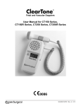
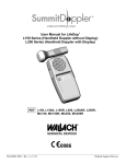
ABI
VASCULAR SYSTEM
User Manual
Listening to LifeTM
Thank you for choosing Summit Doppler Systems. We believe you have
purchased the finest handheld Doppler and portable printer on the market.
Your total satisfaction is our highest priority as we strive to continually
improve our products and services. Please contact us with any suggestions.
We look forward to enjoying a long-term relationship with you!
Warranty and Servicing Policy
Summit Doppler Systems, Inc. is pleased to present our customers with a 30day no hassle evaluation return policy in the event that you are not satisfied
with our product.
The warranty on this product is that it will be free from defects in material
and workmanship for 12 months from the original sale of the device. This
includes all parts and labor required to repair or replace the unit to original
specifications and shipping costs associated with sending the product back to
the customer. Customer is responsible for providing adequate packaging
materials and shipping costs to Summit Doppler Systems. Products shall be
repaired or replaced in a reasonable amount of time.
Summit Doppler Systems, Inc.
4680 Table Mountain Dr. #150
Golden, CO 80403
Here’s how you can reach us…
Phone: 1-800-554-5090
(303) 423-7572
Fax:
(303) 940-7165
e-mail us at: [email protected]
Visit our website at: www.SummitDoppler.com
Summit Doppler Systems’ liability for any claim is limited to materials and
labor associated with repair or replacement. In no event shall Summit
Doppler Systems be liable for incidental or consequential losses or damages
in connection with the purchase of this product.
Table of Contents:
Intended use/Contraindications/Warnings………...
Description of product (table of features)…………
Operation and Installation…………………………
Obtaining Doppler Signals………………………..
Printer Operation……………………………….....
Diagnostic Monitoring ……………………………
Accessories………………………………………..
Maintenance/Cleaning…………………………….
Replacing/Recharging Batteries…………………..
Clinical References……………………….…...…..
Specifications…………………...…………………
Trouble shooting………………………………….
Warranty…………………………………………..
Page
3
4
5
8
8
12
12
13
14
16
17
18
19
Please read the manual carefully and become familiar with the operation,
features and maintenance of your Doppler prior to using the device or
accessories.
0470
Authorized Representative
BellyTalk BV
Benedictijnenstr. 8
1566LB Assendelft
Holland
Summit Doppler Systems disclaims all express or implied warranties,
agreements or arrangements other than issued in this warranty unless
specified in writing and signed by the President of Summit Doppler Systems.
Summit Doppler Systems is not responsible for damages to the device that
occur as a result of the inadequate shipping to Summit Doppler Systems,
improper maintenance or cleaning as described in the user manual, misuse,
abuse, alteration of the equipment from it’s original specifications, or
dismantling the unit (other than by Summit Doppler Systems approved
service technicians).
Service Returns: To return products to Summit Doppler –
1. Call Summit Doppler Systems to obtain a Return Authorization and to
receive any final instructions prior to shipping
2. Clean the product prior to shipping
3. Ensure the device is well-packaged and suitable for shipment
Send the product to:
Service Department
Summit Doppler Systems, Inc.
4680 Table Mountain Dr. #150
Golden, CO 80403
For customer service, technical service, cleaning, maintenance or shipping
questions please call (303)423-7572 or 1-800-554-5090.
Manual Part Number: MAN0007 Rev G
19
Transducer Model: LifeDop 5 MHz Bi-DirOperating Mode: Continuous-Wave (cw)
Application(s): Peripheral Vascular
ISPTA.3
ISPPA.3
ACOUSTIC OUTPUT
MI
(mW/cm2)
(W/cm2)
500
0.5
32.7
5.50
0.32.7
5.50
(cm)
0.85
0.4
0.85
0.4
Beam Dimensions
y-6 (cm)
Az (cm)
0.6
0.4
0.6
EBD
Ele. (cm)
0.8
Global Maximum Value
Pr.3
wo
fo
Associated
Acoustic
Parameter
zsp
0.05
0.12
(Mpa)
(mW)
(MHz)
(cm)
x-6
5.50
0.85
Transducer Model: LifeDop 8 MHz Bi-Dir Operating Mode: Continuous-Wave (cw)
Application(s): Peripheral Vascular
ISPTA.3
ISPPA.3
ACOUSTIC OUTPUT
MI
2
Global Maximum Value
Pr.3
wo
Associated
Acoustic
Parameter
ISPTA.3
ISPPA.3
MI
Pr.3
Wo
fc
zsp
x-6, y-6
EBD
fo
zsp
0.04
0.116
(Mpa)
(mW)
(MHz)
(cm)
8.43
0.63
Beam Dimensions
x-6
y-6
(cm)
(cm)
EBD
Az (cm)
Ele. (cm)
2
(mW/cm )
(W/cm )
365
0.37
15.7
8.43
0.63
0.42
0.14
0.6
0.3
15.7
8.43
0.63
0.42
0.14
the derated spatial-peak temporal-average intensity (mwatts per cm2).
the derated spatial-peak pulse-average intensity (watts per cm2).
the Mechanical Index.
the peak rarefactional pressure (megapascals) associated with the transmit pattern giving rise
to the value reported for MI.
the total time-average ultrasonic power (mwatts).
the probe center frequency (MHz).
the axial distance at which the reported parameter is measured (cm).
are the –6dB beam dim. in the x-y plane where zsp is found (cm).
the entrance beam dimensions (cm). These dimensions are the same as the dimensions of the
transmit crystal.
Measurement Uncertainties:
Power:
Pressure:
Intensity (Ispta):
Frequency:
+34, -42%
+11, -16%
+23, -26%
+/- 5%
Acoustic Output Parameters are measured in water. Derated values, denoted by the subscript “.3”, take into
account a conservative level of attenuation that would be encountered in the human body. The derated
intensity values (I.3) are obtained from water values of intensity (Iw) at a depth of z calculated by:
I.3 = exp(-0.23*0.3*f*z)*Iw
(where f is the probe frequency in MHz and z is the depth in centimeters)
The derated peak rarefactional pressure is calculated from the value of measure water (pr) by:
Pr.3 = exp(-0.115*0.3*f*z)*pr
(where pressure is given in megapascals)
Additional Output Reporting Information for IEC 61157
8 MHz: Iob < 112 mW/cm2
Note that parameter Zsp in the probe reporting tables is the same parameter as Ip in IEC 61157.
Operating Conditions: There are no user controls which affect the
ultrasound output.
18
Summit Doppler Systems, Inc. provides general reimbursement information
related to the diagnosis of peripheral arterial disease as an overview for our
customers. It is important to understand that reimbursement is a complex
process and requirements are subject to change without notice. It is the
responsibility of the healthcare provider to determine and submit appropriate
codes, charges, and modifiers for services that are rendered. Prior to filing
any claims, customers are advised to contact their third-party payers for
specific coverage, coding and payment information. Summit Doppler
Systems, Inc. makes no promise or guarantee of reimbursement by
Medicare or any other third-party payer.
Intended Use
This product will be used to detect blood flow in veins and arteries for
assisting in the detection of peripheral vascular disease.
Federal law restricts this device to sale by or on the order of a licensed
practitioner.
Contraindications
Warning: The vascular probes are not for fetal use.
Warning: The ultrasound probes are not to be used on or near the eyes.
Warning: The device is for use only on intact skin.
Warning: Do not plug any part of this device into a telephone or modem.
Warning: This device is not intended for use with HF surgical equipment.
If there are questions or concerns regarding these warnings or
contraindications, please do not hesitate to contact Summit Doppler Systems
for further clarification.
In order to preserve, protect and improve the quality of the
environment, protect human health and utilize natural resources
prudently and rationally – do not dispose of waste electrical or
electronic equipment (WEEE) as unsorted municipal waste.
Contact local WEEE disposal sites or Summit Doppler Systems
to dispose or equipment.
Safety of Ultrasound
The Summit Doppler was designed with physician and patient safety in
mind. In early design phases all potential hazards were eliminated or
reduced to As Low As Reasonably Achievable (ALARA) by adhering to
good design practices and industry wide safety standards. Ultrasound
procedures should be performed with the ALARA principle in mind when
delivering ultrasound energy into the body.
3
The following official statements from the American Institute of Ultrasound
Medicine (AIUM) are provided for your general information regarding the
safe use of ultrasound.
Clinical Safety
Approved March 1997, October 1982
Diagnostic ultrasound has been in use since the late 1950s. Given its known
benefits and recognized efficacy for medical diagnosis, including use during
human pregnancy, the American Institute of Ultrasound in Medicine herein
addresses the clinical safety of such use:
There are no confirmed biological effects on patients or instrument operators
caused by exposures from present diagnostic ultrasound instruments.
Although the possibility exists that such biological effects may be identified
in the future, current data indicate that the benefits to patients of the prudent
use of diagnostic ultrasound outweigh the risks, if any, that may be present.
Prudent Use
Approved May 1999
The AIUM advocates the responsible use of diagnostic ultrasound. The
AIUM strongly discourages the non-medical use of ultrasound for
psychosocial or entertainment purposes. The use of either two-dimensional
(2D) or three-dimensional (3D) ultrasound to only view the fetus, obtain a
picture of the fetus or determine the fetal gender without a medical
indication is inappropriate and contrary to responsible medical practice.
Although there are no confirmed biological effects on patients caused by
exposures from present diagnostic ultrasound instruments, the possibility
exists that such biological effects may be identified in the future. Thus
ultrasound should be used in a prudent manner to provide medical benefit to
the patient.
Safety in Training and Research
Approved March 1997, March 1983
Diagnostic ultrasound has been in use since the late 1950s. There are no
confirmed adverse biological effects on patients resulting from this usage.
Although no hazard has been identified that would preclude the prudent and
conservative use of diagnostic ultrasound in education and research,
experience from normal diagnostic practice may or may not be relevant to
extended exposure times and altered exposure conditions. It is therefore
considered appropriate to make the following recommendation:
In those special situations in which examinations are to be carried out for
purposes other than direct medical benefit to the individual being examined,
the subject should be informed of the anticipated exposure conditions, and of
how these compare with conditions for normal diagnostic practice.
4
Specifications
Degree of protection against electric shock:
Type B Applied part
Class II Equipment
Degree of protection against ingress of water:
IPX4 – extending 2.5 cm from tip
IPX1 – entire probe 2.5 cm from tip, excluding connector
Designed and tested to meet:
IEC601-1, IEC60601-1-2, IEC60601-1-4, IEC60601-2-37, EN5011-A
Connect the LifeDop only to equipment that meets the appropriate standards.
Dimensions (h w l):
Weight:
LifeDop
140x70x35 mm
320 grams
Printer
136x84x43 mm
280 grams
Operating temperature:
10 to 40 C
0 to 40 C
Operating humidity:
30 to 75 %
20 to 85 %
Transport/Storage temp:
–20 to 50 C
–20 to 60 C
Transport/Storage humidity:
5 to 90%, non-condensing for both units
(beyond 30 days, battery to be stored between –20 and 30 C)
Battery life
Battery voltage, type
LifeDop
100, 4-minute exams
AA Alkaline 1.5V x3
Printer
500 prints
Lithium Ion 3.7V
Audio bandwidth and power:
Audio cable pin out:
245 Hz – 4 KHz, 0.33 W
3.5 mm stereo plug
Tip - toward, Ring - away, Shaft – common
Note: Common is not a ground connection
Printer Paper Type/Size (max):
Printer Speed:
Printer Resolution:
Printer Impact Resistance:
Printer Communication:
Thermal, 58mm wide, 33mm diameter
35mm/sec, 8 seconds for standard printout
48mm wide, 8 dots/mm, 384 dots/line
1.5 meter on linoleum floor
RS232, 8 data bits, 1 stop bit, no parity,
115.2Kbaud
Input – 100-120VAC, 29VA, 50/60Hz
Output – 5VDC, 2.3A, center positive
Auto scaled to max 4KHz, 2KHz and 1KHz
25mm/sec, 100 mm length w/ 4 sec of data
175 mm total with header
Printer Recharger:
Waveform Frequency Scale
Waveform Time Scale
Printout Length
Attention: Consult Accompanying Documents
Additional technical information is available upon customer request.
17
Printer Not Printing (Error 9)
The LifeDop and printer have lost communication. This may be due to a
printer jam, paper empty, low printer battery or any of the above printer error
codes. To clear the error, lift the paper cover lever, reseat the paper roll and
close the cover. If printer communication is re-established, the LifeDop will
automatically print the buffered waveform. If Error 9 persists, turn off both
printer and LifeDop and re-start waveform buffer.
Waveform appears to be the same above and below the base line
This anomaly normally occurs when the probe is close to perpendicular to
the vessel. Reacquire the Doppler signal with the probe angle at 45 degrees
as described in Obtaining Doppler Signals.
Description of product
The Summit LifeDop ABI is factory configured to include many features and
product enhancements. Along with interchangeable ultrasound transducers,
the Summit Doppler device is well suited to meet your specific needs.
Main Unit
The main handheld unit is ergonomically designed to fit the palm of your
hand with comfort and allow easy access to each control feature. Each unit
is individually tested and inspected to ensure the highest quality standards.
Printer Download – The LifeDop buffers 4 seconds of waveform data and
waits until the printer is ready to print out a record of the examination.
Faint signal is audible, but waveform is not obtained on printout
The LifeDop main unit is designed to reject noise and certain artifacts.
Even a valid signal must reach a threshold before it can be printed; therefore
it is normal for some very weak signals to be rejected.
LCD Display – The LCD display allows you to view information in large
easy to read digits including probe ID, battery life, signal strength indicators,
and multiple diagnostic indicators that ensure your unit is functioning at
peak performance levels.
Printer Switches not set in proper location
The printer switches have been preset at the factory to the proper location,
however if they have been changed the printer will not function. Orient the
printer and set the DIP switches to match the following:
SSQ – Superior Sound Quality. LifeDop ABI is designed with a state of the art
sound system that produces excellent sound quality and long-term reliability.
1 – Up
2 – Down
3 – Down
4 – Down
Reference materials for Peripheral Vascular testing:
Noninvasive Diag of Peripheral Vascular Disease; W. Robert Felix, Jr., 1988
Current Noninvasive Vascular Diagnosis; Ali F. Aburahma, Edward B. Diethrich,
1988
Vascular Disease Foundation; www.vdf.org
American Heart Association; www.americanheart.org
American Diabetes Association; www.diabetes.org
16
Main Unit
Catalog#
L250ABI
SSQ
X
Feature
Display Download
X
X
Probe
Summit Doppler ultrasound transducers were designed to meet your specific
application need. Each probe has been ergonomically designed for comfort
while providing excellent maneuverability for locating the vascular target.
Every probe is carefully measured and tested to ensure it meets exacting
performance standards.
8 MHz Directional Probe – This standard “pencil” style probe is an excellent
vascular tool for locating specific shallow vessels in the peripheral vascular
system. The narrow grip and small face of the probe make it ideal for
maneuvering for maximizing the signal in both flow directions.
5 MHz Directional Probe – This “pencil” style probe, with wide beam and
deep penetration, is designed for locating deep vessels in the peripheral
vascular system. The narrow grip is easy to maneuver.
Probe
Catalog #
SD8B 8 MHz Bi-Dir
SD5B 5 MHz Bi-Dir
Application
PV ABI PV General
X
X
X
X
5
Operation and Installation
Trouble shooting
Warning: Use alternate equipment in case of unit failure. Call Summit
Doppler Systems Service Department if the probe or main unit
malfunctions.
Warning: Do not drop or mishandle the LifeDop, probes or accessories.
Damage to sensitive electrical components, speakers, cables,
transducers or plastic likely to occur.
PROBE
CONNECTOR
HEADPHONE
CONNECTOR
Poor sound quality
Inadequate gel use
Try and relocate the probe for a better signal
Improper choice of probe Frequency
Interference from other equipment
Probe coiled cable or battery contacts may be intermittent
Debris in the speaker may cause poor sound
Device damage from dropping the LifeDop, probes or accessories
PRINTER
CONNECTOR
Battery indicator flashing – Error 5 or Error 7
Consult Diagnostic Monitoring, replace batteries as described in Replacing
Batteries
PRINT
BUTTON
Probe frequency does not match the connected probe
Check probe that is attached to ensure it is the correct one, or no probe attached
If correct probe, contact Summit Service
Side Panel Controls
Radio Frequency Interference
The LifeDop was tested for immunity to electromagnetic interference at a
level of 3V/meter. Interference during normal operation may occur in the
presence of fields stronger than 3V/meter. If this occurs, try to increase the
distance between the LifeDop and the source of interference. Contact
Summit Doppler for more information.
Printer LED Red or Orange
Green
Orange
Red
LED
LED
LED
Flash 2x
Flash
Flash 1x
Flash 2x
Flash 3x
Flash 4x
Error
Solution
No Error
Low Battery
Out of Paper
Open Cover
Thermal Failure
Voltage Failure
Normal
Recharge
Reload Paper
Close Cover
Call Summit
Call Summit
Printer DIP switches are preset at the factory. The printer will not function
properly if they are moved from these set positions.
6
15
Replacing LifeDop Batteries
(NOT USED)
Warning: Replace batteries only with batteries supplied by Summit Doppler
Systems. The battery compartment only accepts AA size batteries.
See accessories list for part number and re-order information.
(NOT USED)
Open the battery compartment by depressing the tab and pulling outward on
the battery door. Remove the existing drained batteries by pushing on the
end of the battery that compresses the battery contact spring and lift
upwards. It is acceptable to use a small tool or pen to assist in this step.
(NOT USED)
LCD Display
Replace the batteries by paying close
attention to the polarity indicators on the
battery and the polarity indicators on the
battery holder in the compartment.
Positive (+) aligns with positive (button)
and negative (-) aligns with negative
(spring). Insert the battery such that the
spring contacts are loaded first and then
press the battery firmly into place.
Warning: If the batteries have been inserted incorrectly, the unit will not
function but the LifeDop will not be damaged.
(NOT USED)
Recharging Printer Batteries
Warning: Use only the battery and AC adapter supplied with the printer.
Use of any other battery and/or AC adapter is hazardous and may
cause damage to the equipment.
(NOT USED)
A comprehensive In-Service Training Video is now available.
Warning: Do not connect the printer to the Doppler while the printer is
charging.
Printer Recharger
14
Turn the printer off. Lift the
rubber flap on the left side of the
printer and plug in the connector
of the recharge adaptor. Make
sure recharger is plugged into a
standard 120VAC outlet. When
properly connected, the LED will
be red. Upon completion of
charging the LED will be green.
Remove the recharger and replace
the rubber flap
Turning Unit On/Off
Turn the LifeDop on by pressing the On/Off button. LCD indicators show
power status. The LifeDop automatically shuts itself off after 5 minutes if it
is not being used.
Turn the Printer on by pressing and holding the On/Off button until the green
LED comes on (approximately 3 seconds). Printer automatically shuts itself
off after 30 minutes.
Volume Slider
The audio level can be adjusted using the Volume Slider. Moving the slider
up will increase the volume, while moving it down will decrease it. The
volume slider does not affect the headphone output.
7
Obtaining Doppler Signals and Printer Operation
Caution: Doppler examinations should be performed only by trained
individuals.
For any Doppler examination, it is essential that an adequate supply of
coupling gel be used to transmit the ultrasound energy from the probe to the
surface of the skin. Re-apply more gel if it starts to dry out or spread so
thinly that an air gap occurs between the probe and the skin. It is not
necessary to cover the entire surface of the probe, only the probe face.
Applying too much gel makes the unit difficult to clean and does not aid in
the performance of the probe.
For the best results, angle the probe approximately 45 degrees from the skin
surface over the general location of the vessel. Slowly move the probe side
to side and vary the angle of the probe until the vascular sounds are heard.
Changing the angle of the probe has an affect on the frequency of the sound.
The steeper the probe angle, the higher the frequency of the sound.
Maintenance and Cleaning
Warning: The LifeDop is not designed for liquid immersion. Do not soak
or drop the Doppler main unit or probes in liquids. Use only spray
or wipe cleaners and disinfectants.
Warning: The LifeDop is not designed for sterilization processes such as
autoclaving or gamma radiation.
Warning: The LifeDop is not intended to be used on open skin. If there is
evidence of open wound contamination, disinfect the probe before
using again as described below.
The LifeDop Doppler requires very little maintenance. However, it is
important to continuing function of the unit and the health of the patients that
the unit is cleaned and examined regularly per the following guideline:
After every examination:
Excess gel should be wiped off prior to docking the probe. Probes and main
unit should be cleaned with a damp warm water cloth or presaturated
isopropyl alcohol wipes or spray such as Transeptic® from Parker
Laboratories, Inc. In particular, pay close attention to clean the seams along
the plastic lines at the probe face but do not allow water or spray to enter
through the connectors or speaker grill.
To disinfect unit, use commercially available spray or wipe disinfectants
registered with the EPA – such as Precise® QTB from Caltech Industries, Inc.
Follow the manufacturers instructions and wipe unit until it is dry of solutions.
Examiners should wash hands and change gloves after every exam. Refer to
local and hospital policies for cleaning and disinfection policies.
Signal Quality Indicator
Once flow sounds are found, the signal strength indicators give the user a
visual display of the flow direction and relative strength of the signal. Four
bars of the left indicate flow toward the probe, while the four bars to the
right indicate flow away from the probe. Vary the probe position and angle
as described above while viewing the indicators to obtain the best results.
Buffering a Waveform
Once the desired flow is found, press the red “PRINT” button on the side of the
unit to buffer the PREVIOUS four seconds of flow. When the waveform is
buffered, as indicated by “STR” on the display, the probe is temporarily shut
off and can be removed from the patient. The printer need not be connected to
buffer the waveform - the LifeDop waits until the printer is ready.
Store unit in a clean area free from dust and debris. Follow temperature and
humidity guidelines as specified at the end of this manual.
Warning: If the unit is to be stored for longer than 90 days without use,
remove the batteries prior to storage.
Periodically (at least annually):
Inspect the main unit and probes for signs of cracks or breaks in the
mechanical housing. Inspect cables and connectors for signs of wear or
failure. The user should discontinue use of the unit with any sign of loss of
housing integrity. Contact Summit Doppler Systems for service.
It is recommended that rechargeable batteries be replaced annually.
Note: Only one waveform can be buffered at a time and the LifeDop must
remain ON in order to retain the waveform.
8
13
Diagnostic Monitoring
All LifeDop Doppler units perform continuous diagnostic monitoring and give
a visual indication of battery level. The LifeDop uses a multiple level battery
shaped icon that indicates the voltage level of the battery. The battery outline
will flash when the battery level is very low indicating that the user should
change the batteries soon after the current examination is complete.
Once the unit is on, the LifeDop performs a series of diagnostic checks. The
unit first checks and displays the frequency of the probe that is being used.
This display will not change unless the probe is changed or the power is
cycled, in which case the display will again temporarily confirm the
frequency of probe that is connected.
Connecting the Printer
Ensure that the printer is loaded with paper and connect the cable to the
printer and LifeDop as shown, with connector tabs down as labeled “THIS
SIDE UP”. Turn the printer on by HOLDING the power button down
(approx. 3 seconds) until the LED comes on. If the printer is functioning
properly and ready to print, the LED will flash green twice every second.
Warning: Forcing the cable upside down will cause damage to the connector
pins on the LifeDop, cable and printer. Note label “THIS SIDE UP”.
Note:
When turning the printer on or off, it is important to remember to
hold the button down, approximately 3 seconds, before the printer
will respond.
The unit then checks for proper internal operating temperature, battery
voltage, reference voltage and power supply voltage levels. If any of these
characteristics are out of range, the display will show the ERROR icon and a
failure code associated with the diagnostic error. Diagnostic functions are
periodically checked while the unit is on to ensure the Doppler is operating
at peak performance. Refer to the table below for failure codes.
Diagnostic Codes – Contact Summit Service
1 – Temperature too low
5 – 5 Volt Supply too low
2 – Temperature too high
6 – 5 Volt Supply too high
3 – Reference Voltage too low
7 – Battery Voltage too low
4 – Reference Voltage too high
8 – Battery Voltage too high
9 – Printer miscommunication
The printer will perform a self-test print by turning the printer on while the
feed button is being held down. A checkered test pattern will print in
addition to the printer configuration and loaded fonts.
Loading Paper
Warning: Install the paper roll in the printer so the external side (heat
sensitive side) of the rolled paper is against the print head (down).
Warning: Do not use printer paper other than the type specified and
supplied by Summit Doppler. Other paper types could result in
damage or degraded print quality and may void the warranty.
Accessories
Contact Summit Service at 1-800-554-5090 or (303) 423-7572 to order by
phone, or order on-line on our website www.SummitDoppler.com
Description
Alkaline battery
Lithium Ion battery
Carry Case
User Manual
Quick Reference Guide
ABI Assessment Form
ABI In-Service Video
12
Part Number
BAT0002
BAT0004
PKG0003
MAN0007
MAN0008
MKT0042
MKT0076
Description
Part Number
Coiled Cable
CBL0001
Printer Cable
CBL0011
Gel (60 gm)
GEL0001
Gel (250 gm)
GEL0002
Printer Paper (Labels) MMH0014
Printer Paper (10 yr) MMH0015
Printer Connections
9
Printing a Waveform
Report Generation
Warning: The print head becomes hot during printing. Do not touch the
print head after printing.
Report generation is made very simple with adhesive backed printer paper
provided by Summit Doppler - eliminating the need to cut and tape the strip
of paper. The label paper backing is precut down the center – fold the paper
down the middle and peal from the center. Attach the waveform to the preprinted ABI assessment Form.
Warning: Turn off the printer and check that the head is fully cooled before
attempting to fix a paper jam, replacing paper, or removing the
print roller for any reason.
Once the printer is operational and the cables are in place, the LifeDop will
automatically download the waveform and printing will begin. If the PRINT
button is pressed while the printer is connected and ready, printing will start
immediately. Waveforms are automatically scaled to a maximum frequency
of either 1 KHz, 2 KHz or 4 KHz for optimal waveform height. Markings on
the vertical axis are provided every 1 KHz. Printer calibration is not
required.
Auto-Scaling – 1 kHz, 2 kHz and 4 kHz
Printout
Blood flow in the direction toward the probe is shown above the baseline.
Flow away from the probe is shown below the baseline. These two traces are
provided so that flow in both directions can be displayed simultaneously.
ABI Assessment Form
11
10