1
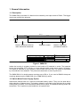
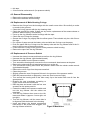
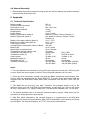
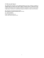
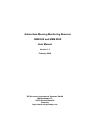
Subsurface Mooring Monitoring Beacons
SMM 500 and SMM 500X
User Manual
Version 1.3
February 2008
SiS Sensoren Instrumente Systeme GmbH
Mühlenkoppel 12
24222 Schwentinental
Germany
http://www.sis-germany.com
Contents
1. General Information ..............................................................................................2
1.1 Description ........................................................................................................2
1.2 Switch Mode Power Supply Option.................................................................2
2. Operating Instructions ..........................................................................................3
2.1 Choosing Batteries for your Application ........................................................3
2.2 Opening the Housing........................................................................................3
2.3 Insertion of Batteries ........................................................................................3
2.4 Replacement of Moisture Absorbent ..............................................................3
3. Principle of Operation ...........................................................................................4
3.1 SMM Operation..................................................................................................4
3.2 CLS Argos Localisation Service......................................................................4
3.3 Admission to the Argos System......................................................................4
4. Maintenance...........................................................................................................4
4.1 Maintenance Notes ...........................................................................................4
4.2 Maintenance Parts and Tools ..........................................................................4
4.3 General Disassembly........................................................................................5
4.4 Replacement of Main Housing O-rings ...........................................................5
4.5 Replacement of Pressure Switch ....................................................................5
4.6 General Assembly.............................................................................................6
5. Appendix ................................................................................................................6
5.1 Technical Specification ....................................................................................6
5.2 Warranty and Support ......................................................................................7
List of Figures
Figure 1 SMM 500 ......................................................................................................2
Figure 2 Membrane....................................................................................................5
1
1. General Information
1.1 Description
The SMM 500(X) consists of a titanium tube closed by end caps made of Delrin. The bigger
upper cap contains the antenna.
60,3 +0.7
853,0
198,0 +/-1.0
81,0 +/-1.0
574,0 +/-1.0
Titanium tube
Delrin antenna dome
with internal antenna
Delrin cap with
pressure switch
Scale
Date
Clrk
Chkd
Norm
Name
12.10.93 Ar
Sensoren
Instrumente
Systeme GmbH
Rev Modification
Date
Name
SMM 500
Sheet
of
1
1
Figure 1 SMM 500
Inside the housing is a battery holder for one bundle of 5 batteries in series. The batteries
power the transmitter (PTT) directly or via an optional switch mode power supply (X Option).
The power is switched on by a pressure switch inside the lower cap. The switch is separated
by a membrane from seawater. The pressure transmission is done by silicon oil.
The SMM 500X is for shallow water moorings up to 500 m. If you need a SMM for deep sea
moorings please use the SMM 2000 (X) or SMM 6000 (X) series.
1.2 Switch Mode Power Supply Option
Instruments marked with an X have the extended battery option. They can be used with a
wider selection of battery types. The battery voltage is converted to the right level by a switch
mode power converter. For instruments without the X-option, the batteries directly power the
transmitter. The X-option may be installed to all systems later.
2
2. Operating Instructions
2.1 Choosing Batteries for your Application
The cell voltage has to be between 2.2 V and 5.2 V. For instruments with the X-option the
cell voltage has to be between 0.8 V and 5.2 V allowing the usage of alkaline batteries or
nickel cadmium accumulators as well. For long term moorings in cold environment we
recommend to use high quality Lithium cells.
The batteries must be able to source 350 mA continuous current and 1700 mA pulse current.
So you should use a battery type which has good efficiency with high currents. This applies
especially to Lithium and Lithium Thionyl Chloride Batteries.
For calculation of battery lifetime use the average power consumption when surfaced. Divide
the energy content of the 5 batteries by the mean power consumption (100 mW) of the
beacon. The table shows typical life times for different battery types:
Temperature
20 °C
0 °C
-30 °C
Lithium battery:
Alkaline battery:
NC battery:
Lithium
75 days
75 days
70 days
Alkaline
30 days
25 days
not applicable
NC
15 days
14 days
not applicable
Silberkraft Eternacell, Lithium-SO2, Size D, Capacity 10 Ah
Philips LR20, Green Alkaline, Size D, Capacity 13.2 Ah
Panasonic 4000N, NC, Size D, Capacity 4 Ah
For instruments without the X option use the Lithium values only!
2.2 Opening the Housing
You open the housing by removing the end caps. The caps are fastened with the tube by
threads. For opening please screw the lower cap anti-clockwise thereby turning the cap out
of the tube.
The inner part is fastened at the upper cap. Normally you don't have to remove the instrument from the housing.
2.3 Insertion of Batteries
Don't open the housing by removing the upper cap. Open the housing by removing the lower
cap.
You will now find a PVC disc, take it out and you will see a tube in a PVC block. Put 5 pieces
D type batteries into the tube oriented with the plus terminal in direction of the antenna cap.
If you want the instrument to operate after insertion of batteries, close the housing by
screwing in the lower cap clockwise.
In case you only want to insert batteries but later on want to operate, please place the PVC
disk for isolation between batteries and cap.
2.4 Replacement of Moisture Absorbent
The printed circuit boards are protected by coating, but condensation of humidity should be
avoided. When leaving the factory, the instrument is filled with dry argon gas and four small
packs with moisture absorbent are placed in slots between the battery holder and the
titanium housing at the lower end. We recommend filling with dry gas or replacing the
moisture absorbent after every opening of the housing. Normally together with battery
3
replacement. With the instrument we deliver some packs with moisture absorbent sealed in a
plastic bag.
3. Principle of Operation
3.1 SMM Operation
The SMM 500 subsurface mooring monitoring beacons go down with the mooring up to
500 m with the PTT cut off by the pressure switch. If the mooring line should break, or when
the mooring is being recovered, the PTT will switch on as it approaches the surface. In the
first case, the beacon will transmit for the lifetime of the batteries (typically 3 months) in the
second, the beacon is manually switched off after recovery.
3.2 CLS Argos Localisation Service
CLS Service Argos has developed a special service for monitoring the status of the
moorings. An alarm state is set upon reception of the signal by an orbiting satellite and
recognition and processing at a ground centre. A warning that the mooring has surfaced, with
its position, will be sent to the user by email, fax or telex. Thereafter each satellite pass will
result in another location and another alarm message until a specified maximum number of
messages has been sent. Generation of alarm messages may be cancelled by the user at
any time. Users always may access data on-line (e.g. via Telnet).
3.3 Admission to the Argos System
The user must fill out some forms and forward it to the Argos User Office:
• Argos System Use Agreement
• Service Contract/Order Form
Please see the Argos documentation for detailed information.
4. Maintenance
4.1 Maintenance Notes
The replacement of the wearing parts, described below, should only be done by qualified
technical personnel. Inexpert handling can produce serious damage.
4.2 Maintenance Parts and Tools
Requires (depends on the parts to be replaced):
• SMM 500 pressure switch spare part kit with:
1 x SMM 500 pressure switch (adjusted to 3 - 5 m)
1 x O-ring, 15.6 x 1.78, 90 shore
1 x O-ring, 4.47 x 1.78, 90 shore
1 x silicon oil (AK 100, Wacker Chemie, FRG)
1 x membrane (60EPDM/266, Carl Freudenberg, Reichelsheim, FRG)
4 x slotted countersunk head screw, DIN 963, M3x8, titanium
• SMM 500 housing O-rings
4 x O-ring, 52.07 x 2.62, 90 shore
• silicon paste (e.g. TEGO-Silikonpaste S 200, Th. Goldschmidt AG, Essen, FRG) or
silicon-based O-ring lubrication (e.g. Super-O-Lube, Parker)
• cleaning cloth (not napped)
• screw driver for M3 screws (for pressure switch plate)
• screw driver for M4 screws (for pressure switch connection)
• small screw driver
4
• thin tape
• 24 mm tubular socket wrench (for pressure switch)
4.3 General Disassembly
• Remove the pressure switch housing.
• Remove the antenna dome housing.
4.4 Replacement of Main Housing O-rings
• Remove the O-rings from the housings with the small screw driver. Be carefully to make
no marks in the grooves.
• Clean the O-ring grooves with the dry cleaning cloth.
• Check the grooves for marks. If there are any marks, replacement of the antenna dome or
pressure switch housing is necessary.
• Cover up the ring followers at the housings with the tape.
• Check the new O-rings for damage.
• Grease the O-rings very slightly with the silicon paste. There should only be a thin film on
the rings.
• Put a piece of paper around the battery tube and slide two O-rings over the paper.
• Push the paper with the O-rings over the battery tube and the ring follower and fit the Orings in the grooves of the antenna dome.
• Fit the other two O-rings in the grooves of the pressure switch housing.
• Remove the tape from the ring followers.
4.5 Replacement of Pressure Switch
•
•
•
•
•
•
•
•
•
•
•
•
•
•
•
•
•
Unscrew the slotted countersunk head screw from the ring follower.
Unscrew the ring follower (right-handed thread).
Detach the cables from the pressure switch.
Turn around the housing and unscrew the four countersunk head screws at the plate.
Remove the plate and the old membrane and pour out the oil.
Turn around the housing and loosen the pressure switch with the tubular socket wrench
(right-handed thread).
Remove the old O-rings from the pressure switch.
Clean the grooves.
Slightly grease the new O-rings and fit them in the grooves of the pressure switch.
Refit the pressure switch or replace by a new one (don't screw too tight).
Turn around the housing and fill the hole nearly up to the border with new oil from the
spare parts kit.
Prepare the new membrane according to
Figure 2 and insert the membrane.
Refit the plate and screw it with the four new
screws from the spare parts kit.
Fasten the cables at the pressure switch and
turn the ring follower until the cables are
untwisted.
Turn the ring follower three turns to the left,
insert and fasten it (approx. 6 turns right, not
too tight).
Turn the ring follower until the screw hole is
in alignment with the thread in the housing.
Insert and fasten the slotted countersunk
head screw. If the screw turns sluggish, turn
the ring follower a little bit.
Figure 2 Membrane
5
4.6 General Assembly
• Reassemble the pressure switch housing at the end with the battery sign and the antenna
dome housing at the other side.
5. Appendix
5.1 Technical Specification
Mooring depth
Pressure switch threshold
Dimensions (l x d)
Mass without batteries
Displacement
Power Supply
Battery Types without option X
Battery Types with option X
500 m
3-5m
853 x 60.3 mm
3.8 kg
2.4 dm3
5 pcs. D cells
Lithium or Lithium Thionyl Chloride (1)
NC, Alkaline, Lithium or Lithium Thionyl
Chloride (1)
2.2 V - 5.2 V
0.8 V - 5.2 V
1700 mA
100 mW
up to 2 years
up to 6 months
3 months
Serpe IESM
Elta / CEIS
PTT 07
UHF 88 or HAL2
33 dBm (2 W)
33 dBm (2 W)
32 bits
32 bits
90 seconds
90 seconds
410.650 MHz
410.650 MHz (UHF88)
410.620 MHz
410.630 MHz (HAL2)
Battery cell voltage (without option X)
Battery cell voltage (with option X)
Peak supply current
Average power consumption when surfaced
Mooring life
Mooring life in euphotic zone
Transmission life with Lithium cells
Transmitter manufacturer (2)
Transmitter model (2)
Output power
Message Length (3)
Repetition rate (4)
Transmit frequency (5)
Notes:
1. The used batteries must be able to source 350 mA continuous current and 1700 mA pulse
current. Some low current types of Lithium Thionyl Chloride batteries can’t be used.
2. There are three transmitter models used with the SMM. Instruments manufactured from
2003 to 2006 are equipped with the Serpe IESM PTT 07 model, those made since 2006 are
equipped with the Elta HAL2 model while older instruments use the Elta / CEIS UHF 88
model.
3. The SMM did not send any user data. Therefore, the message length is set to the
minimum value of 32 bits. With Elta HAL2 transmitters, a prefix byte (typ. 25 hex, with 20-bit
ID only), temperature (°C), supply voltage (mV / 64) and power indication (mV / 4) are send.
4. The default repetition rate is 90 seconds (recommended by Argos). Other rates (e.g. 60
seconds) can be programmed upon request.
5. With Elta HAL2 transmitters, the transmit frequency is programmed to 401.630 MHz
according to the Argos recommendations. With UHF 88 transmitters, the frequency is fixed at
401.650 MHz. The transmit frequency of PTT 07 is set by the manufacturer.
6
5.2 Warranty and Support
SiS warrants this instrument to the original purchaser to be free of defects in material or
manufacturing for a period of two years. Liability is limited to repair or replacement of the
defective part which will be done without charge if the instrument is returned to our factory
prepaid. This warranty does not apply to instruments subjected to misuse or tampering. No
responsibility or warranty for consequential damage is included in the sale of this instrument.
SiS - Sensoren Instrumente Systeme GmbH
Mühlenkoppel 12, D-24222 Schwentinental, Germany
Tel.: +49-431-79972-0
Fax: +49-431-79972-11
Email: [email protected]
WWW: http://www.sis-germany.com
7