1
8004-2
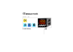
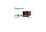
Temperature Controller with Servomotor Output
Chromalox
r USER'S MANUAL
Issue date
May 2000
8004-Tser0-DA.p65
1
5/29/00, 6:50 PM
INDEX
GB
MOUNTING REQUIREMENTS .......................... 1
OUTLINE AND CUT OUT DIMENSIONS ........... 2
CONNECTION DIAGRAMS ................................ 3
PRELIMINARY HARDWARE SETTINGS ........... 9
CONFIGURATION PROCEDURE .................... 10
OPERATIVE MODE .......................................... 18
Display function ......................................... 18
Indicators ................................................... 19
Pushbutton function during operating mode
19
Feedback potentiometer calibration .......... 20
Enable/disable the control output .............. 20
Manual function ......................................... 21
Direct access to the set point .................... 21
operative set point selection ...................... 22
Serial link ................................................... 22
SMART function ........................................ 22
Lamp test ................................................... 23
OPERATIVE PARAMETERS ............................ 23
ERROR MESSAGES ........................................ 26
GENERAL INFORMATIONS ............................ 29
MAINTENANCE ................................................ 33
DEFAULT PARAMETERS ............................... A.1
II
8004-Tser0-DA.p65
2
5/29/00, 6:50 PM
Model identification
Model
8004
1/16 DIN Temperature Controller
Code
21
Outputs
1 servomotor + 1 relay + 3 logic inputs
Code
Output 2 - Alarm
0
None
1
Out #4
2
Out #4 + RS-485
Code
Instrument Power
3
100 - 240 Vac
5
24 V AC/DC
Code
8004 21
1
3
000
Add to complete model number
000
Typical Model Number
III
8004-Tser0-DA.p65
3
5/29/00, 6:50 PM
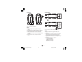
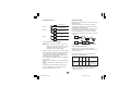
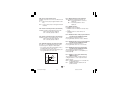
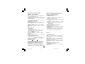
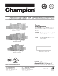
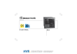
MOUNTING REQUIREMENTS
Select a mounting location where there is
minimum vibration and the ambient temperature
range between 0 and 50 °C.
The instrument can be mounted on a panel up to
15 mm thick with a square cutout of 45 x 92 mm.
For outline and cutout dimensions refer to Fig. 2.
The surface texture of the panel must be better
than 6,3 mm.
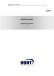
The instrument is shipped with rubber panel
gasket (50 to 60 Sh).
To assure the IP65 and NEMA 4 protection, insert
the panel gasket between the instrument and the
panel as shown in fig. 1.
While holding the instrument against the panel
proceed as follows:
1) insert the gasket in the instrument case;
2) insert the instrument in the panel cutout;
3) pushing the instrument against the panel,
insert the mounting bracket;
4) with a screwdriver, turn the screws with a
torque between 0.3 and 0.4 Nm.
Screw
bracket
Screw
Gasket
Fig. 1
GB
8004-Tser1-DA.p65
1
1
5/29/00, 6:51 PM
Panel
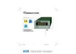
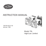
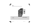
OUTLINE AND CUT OUT
DIMENSIONS
Fig. 2
GB
8004-Tser1-DA.p65
2
2
5/29/00, 6:51 PM
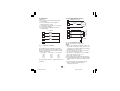
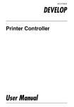
A) MEASURING INPUT
NOTE: Any external components (like zener
barriers etc.) connected between sensor and
input terminals may cause errors in measurement
due to excessive and/or not balanced line
resistance or possible leakage currents.
CONNECTION DIAGRAMS
Connections are to be made with the instrument
housing installed in its proper location.
TC INPUT
+ 1
_ 3
Shield
+ 1
_ 3
Shield
Fig. 4 THERMOCOUPLE INPUT WIRING
Fig. 3
NOTE:
1) Don’t run input wires together with power
cables.
2) For TC wiring use proper compensating cable
preferable shielded.
3) when a shielded cable is used, it should be
connected at one point only.
REAR TERMINAL BLOCK
GB
8004-Tser1-DA.p65
3
3
5/29/00, 6:51 PM
LINEAR INPUT
RTD INPUT
RTD
RTD
mA,
mV
or
_
V
1
+
3
Shield
4
3
1
4
3
+
1
1
_
3
Fig. 5 RTD INPUT WIRING
G
NOTE:
1) Don’t run input wires together with power
cables.
2) Pay attention to the line resistance; a high line
resistance may cause measurement errors.
3) When shielded cable is used, it should be
grounded at one side only to avoid ground loop
currents.
4) The resistance of the 3 wires must be the
same.
GB
8004-Tser1-DA.p65
mA
mV
or
V
4
Fig. 6 mA, mV AND V INPUTS WIRING
NOTE:
1) Don’t run input wires together with power
cables.
2) Pay attention to the line resistance; a high line
resistance may cause measurement errors.
3) When shielded cable is used, it should be
grounded at one side only to avoid ground loop
currents.
4) The input impedance is equal to:
< 5 W for 20 mA input
> 1 MW for 60 mV input
> 200 kW for 5 V input
> 400 kW for 10 V input
4
5/29/00, 6:51 PM
C) VALVE MOTOR DRIVE OUTPUT.
B) LOGIC INPUT
Safety note:
1) Do not run logic input wiring together with
power cables.
2) Use an external dry contact capable of
switching 0.5 mA, 5 V DC.
3) The instrument needs 100 ms to recognize a
contact status variation.
4) The logic inputs are NOT isolated by the
measuring input
17
18
19
s (Open the valve)
Power
line
Servomotor
t (Close the valve)
8
Feedback
potentiometer
20
Log. input 3
21
Log. input 2
7
22
Log. input 1
6
Shield
5
Fig. 8 - SERVOMOTOR WIRING
The two relay outputs are interlocked.
NOTE:
1) Before connecting the instrument to the power
line, make sure that line voltage and the load
current are in accordance with the contact rating
(3A/250V AC on resistive load).
2) To avoid electric shock, connect power line at
the end of the wiring procedure.
3) For servomotor connections use No 16 AWG or
larger wires rated for at last 75 °C.
4) Use copper conductors only.
5) Don’t run input wires together with power cables.
6) For feedback potentiometer, use shielded cable
with the shield connected to the earth at one point
only.
7) The relay outputs are protected by varistor
against inductive load with inductive
component up to 0.5 A.
Fig. 7 - LOGIC INPUT WIRING
This instrument is provided with 3 logic inputs.
The binary combination of the logic input 1 and 3
allows to select the operative set point according
with the following table:
logic input 3
logic input 1 op. set point
open
open
SP
open
close
SP2
close
open
SP3
close
close
SP4
The logic input 2 function is programmed by P 24
parameter.
GB
8004-Tser1-DA.p65
5
5
5/29/00, 6:51 PM
D) RELAY OUTPUTS
14
OUT 3
15
OUT 4
16
INDUCTIVE LOADS
High voltage transients may occur when switching
inductive loads.
Through the internal contacts these transients
may introduce disturbances which can affect the
performance of the instrument.
The internal protection (varistor) assures a correct
protection up to 0.5 A of inductive component.
The same problem may occur when a switch is
used in series with the internal contacts as shown
in Fig. 10.
NO - OUT 3
C - OUT 3/4
NO - OUT 4
17
NO
OUT 1
18
C
Fig. 9 RELAY OUTPUTS WIRING
NOTE: OUT 1 can be used either as servomotor
output or as time proportional relay output;
by the P5 parameter (see pag.11) it is
possible to set the desired output.
Fig. 10 EXTERNAL SWITCH IN SERIES WITH
THE INTERNAL CONTACT
In this case it is recommended to install an
additional RC network across the external contact
as shown in Fig. 10
All relay outputs are protected by varistor against
inductive load with inductive component up to 0.5 A.
The contact rating of OUT 1 is 3A/250V AC on
resistive load, the contact rating of OUT 3 and 4
is 2A/250V AC on resistive load.
The contact rating of the OUT 3 and 4 is 2A/250V AC
resistive load.
The number of operations is 1 x 10⁵ at specified
rating.
Alarm 2 and alarm 3 are in OR condition on the
out 4.
The following recommendations avoid serious
problems which may occur, when using relay
output for driving inductive loads.
GB
8004-Tser1-DA.p65
6
The value of capacitor (C) and resistor (R) are
shown in the following table.
LOAD
(mA)
C
(mF)
R
(W)
P.
(W)
OPERATING
VOLTAGE
<40 mA 0.047 100
<150 mA 0.1
22
<0.5 A
0.33 47
1/2
2
2
260 V AC
260 V AC
260 V AC
Anyway the cable involved in relay output wiring
must be as far away as possible from input or
communication cables.
6
5/29/00, 6:51 PM
SERIAL INTERFACE
RS-485 interface allows to connect up to 30
devices with one remote master unit.
A'/A
B/B'
B'/B
10
9
COMMON
M
A
S
T
E
R
12
8004-Tser1-DA.p65
7
R (S,T)
Fig. 12 POWER LINE WIRING
NOTE:
1) Before connecting the instrument to the power
line, make sure that line voltage corresponds to
the descrtiption on the identification label.
2) To avoid electric shock, connect power line at
the end of the wiring procedure.
3) For supply connections use No 16 AWG or larger
wires rated for at last 75 °C.
4) Use copper conductors only.
5) Don't run input wires together with power cables.
6) For 24 V DC the polarity is a do not care condition.
7) The power supply input is fuse protected by a sub
miniature fuse rated T, 1A, 250 V.
When fuse is damaged, it is advisable to verify
the power supply circuit, so that it is necessary to
send back the instrument to your supplier.
8) The safety requirements for Permanently Connected Equipment say:
- a switch or circuit-breaker shall be included in
the building installation;
- It shall be in close proximity to the equipment
and within easy reach of the operator;
- it shall be marked as the disconnecting device
for the equipment.
Fig. 11 - RS-485 WIRING
The cable length must not exceed 1.5 km at 9600
BAUD.
NOTE: The following report describes the signal
sense of the voltage appearing across the
interconnection cable as defined by EIA for
RS-485.
a) The ” A ” terminal of the generator shall
be negative with respect to the ” B ” terminal
for a binary 1 (MARK or OFF) state.
b) The ” A ” terminal of the generator shall
be positive with respect to the ” B ” terminal
for a binary 0 (SPACE or ON)
GB
POWER LINE 100 V to 240 V A.C
(50/60Hz)
or 24 V AC/DC
N
11
A/A'
N
13
R (S,T)
I
N
S
T
R
U
M
E
N
T
E) POWER LINE WIRING
7
5/29/00, 6:51 PM
NOTE: a single switch or circuit-breaker can drive
more than one instrument.
9) When a neutral line is present, connect it to
terminal 13.
GB
8004-Tser1-DA.p65
8
8
5/29/00, 6:51 PM
OPEN INPUT CIRCUIT
This instrument is able to identify the open circuit
for TC and RTD inputs.
The open input circuit condition for RTD input is
shown by an "overrange" indication.
For TC input, it is possible to select overrange
indication (standard) or underrange indication setting the CH2 and SH2 according to the following
table:
Overrange (STD) CH2 = close SH2 = open
Underrange
CH2 = open
SH2 = close
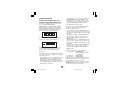
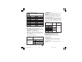
PRELIMINARY HARDWARE
SETTINGS
1) Remove the instrument from its case.
2) It is necessary to set J1 according to the desired
input type as shown in the following figure.
INPUT
J1
TYPE
3-4
5-6
7-8
TC-RTD open
1-2
close
open
open
9-10
open
60 mV
open
close
open
open
open
5V
close
open
close
open
open
10 V
open
open
close
open
open
Both pads are located on the soldering side of the
CPU card
20 mA
open open open close
close
NOTE : the not used jumper can be positioned on
pin 7-9
2
4
6
8
10
1
3
5
7
9
J1
SH2
CH2
V2
Fig. 13
GB
8004-Tser1-DA.p65
9
Fig. 14
9
5/29/00, 6:51 PM
GENERAL NOTES for configuration.
FUNC =
This will memorize the new value of
the selected parameter and go to the
next parameter (increasing order).
MAN = This will scroll back the parameters
without memorization of the new value.
s
= This will increase the value of the
selected parameter
t
= This will decrease the value of the
selected parameter.
CONFIGURATION PROCEDURE
1) Remove the instrument from its case.
2) Set the dip switch V2 to the open condition
(see fig. 13).
3) Re-insert the instrument.
4) Switch on the instrument.
The display will show COnF.
NOTE : If "CAL" indication is displayed, press
immediately the s pushbutton and return to
the configuration procedure.
5) Push the FUNC pushbutton.
SEr1 = Serial interface protocol
OFF = No serial interface
Ero
= Polling/selecting ERO
nbUS = Modbus
jbUS = Jbus
SEr2 = Serial link device address
Not available when SEr1 = OFF
From 1 to 95 for ERO protocol
From 1 to 255 for all the other protocols
NOTE: the electrical characteristic of the RS 485
serial interface will allow the connection of 31
devices maximum.
SEr3 = Baude rate for serial link
Not available when SEr1 = OFF
From 600 to 19200 baud.
NOTE: 19200 baud is shown on display as 19.2.
SEr4 = Byte format for serial link
Not available when SEr1 = OFF
7E = 7 bits + even parity (For ERO protocol only)
7O = 7 bits + odd parity (For ERO protocol only)
8E = 8 bits + even parity
8O = 8 bits + odd parity
8 = 8 bits without parity
P1 - Input type and standard range
0 = TC type L
range
0
1 = TC type L
range
0
2 = TC type J
range-100.0
3 = TC type J
range -100
4 = TC type K
range-100.0
5 = TC type K
range -100
6 = TC type T
range-199.9
7 = TC type N
range -100
8 = TC type R
range
0
9 = TC type S
range
0
10 = TC type B
range
0
11 = RTD type Pt 100 range-199.9
12 = RTD type Pt 100 range -200
13 = mV
Linear range
0
14 = mV
Linear range
12
15 = mA
Linear range
0
16 = mA
Linear range
4
17 = V
Linear range
0
18 = V
Linear range
1
19 = V
Linear range
0
20 = V
Linear range
2
21 = TC type L
range
0
22 = TC type J
range -150
GB 10
8004-Tser1-DA.p65
10
5/29/00, 6:51 PM
/
/
/
/
/
/
/
/
/
/
/
/
/
/
/
/
/
/
/
/
/
/
/
+400.0 °C
+900 °C
+400.0 °C
+1000 °C
+400.0 °C
+1370 °C
+400.0 °C
+1400 °C
+1760 °C
+1760 °C
+1820 °C
+400.0 °C
+800 °C
60 mV
60 mV
20 mA
20 mA
5V
5V
10 V
10 V
+1650 °F
+1830 °F
23 = TC type K
range -150 / +2500 °F
24 = TC type T
range -330 / +750 °F
25 = TC type N
range -150 / +2550 °F
26 = TC type R
range
0 / +3200 °F
27 = TC type S
range
0 / +3200 °F
28 = TC type B
range
0 / + 3310 °F
29 = RTD type Pt 100 range-199.9 / +400.0 °F
30 = RTD type Pt 100 range -330 / +1470 °F
NOTE: selecting P1 = 0, 2, 4, 6, 10,11, 28 or 29,
the instrument set automatically P43 = FLtr. For
all the remaining ranges it will set P43 = nOFL.
P2 = Decimal point position
This parameter is available only when a linear
input is selected (P1 = 13, 14, 15, 16, 17, 18, 19
or 20).
= No decimal figure.
= One decimal figure.
= Two decimal figures.
= Three decimal figures.
----.
---.--.--.---
P3 = Initial scale value
For linear inputs it is programmable from -1999 to
4000.
For TC and RTD input it is programmable within
the input range.
When this parameter is modified, rL parameter
will be re-alligned to it.
P4 = Full scale value
For linear inputs it is programmable from -1999 to
4000.
For TC and RTD inputs, it is programmable within
the input range.
When this parameter is modified, rH parameter
will be re-alligned to it.
The initial and full scale values determine the
input span which is used by the PID algorithm,
the SMART and the alarm functions.
NOTE: the minimum input span (S = P4 - P3), in
absolute value, should be set as follows:
- For linear inputs, S > 100 units.
- For TC input with °C readout, S > 300 °C.
- For TC input with °F readout, S > 550 °F.
- For RTD input with °C readout, S > 100 °C.
- For RTD input with °F readout, S > 200 °F.
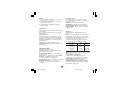
P5 = Output 1 type
Sn.OL= servomotor open loop.
Sn.CL = servomotor close loop.
rEv = time proportional control output with reverse
action
dir = time proportional control output with direct
action.
Reverse
Direct
INPUT
INPUT
t
OUTPUT
t
OUTPUT
t
NOTES:
1) If P5 is changed to "Sn.OL" or it is changed from
"Sn.OL" to another selection, the parameter
P41 will be forced to 0.
2) If P5 is changed to "rEv" the cycle time (Cy1) will
be forced to 15 s
3) If P5 is changed to "dir" the cycle time (Cy1)
will be forced to:
10 s when P25 = Air
4 s when P25 = OIL
2 s when P25 = H2O
GB 11
8004-Tser1-DA.p65
11
t
5/29/00, 6:51 PM
P6 = Valve position indication.
This parameter is available only if P5 = Sn.OL
Fb = the valve position will be displayed
no.Fb = the valve position will not be displayed (the
feedback potentiometer can be omitted)
P7 = Output 3 function.
nonE = output not used.
AL1.P = it is used as Alarm 1 output and the
alarm 1 is programmed as process
alarm.
AL1.b = it is used as Alarm 1 output and the
alarm 1 is programmed as band alarm.
AL1.d = it is used as Alarm 1 output and the alarm
1 is programmed as deviation alarm.
rEv =
it is used as second time proportional
control output with reverse action.
dir =
it is used as second time proportional
control output with direct action.
NOTES:
1) If P7 is changed to "rEv" the cycle time (Cy3) will
be forced to 15 s
2) If P7 is changed to "dir" the cycle time (Cy3)
will be forced to:
10 s when P25 = Air
4 s when P25 = OIL
2 s when P25 = H2O
3) Only one of the two outputs (see P5 and P7)
can be configured as "rEv" control output.
4) Only one of the two outputs (see P5 and P7)
can be configured as "dir" control output.
5) If the servomotor output is selected (P5 ="Sn.OL"
or "Sn.CL") the OUT 3 can be set as alarm
output only (P7 = "AL1.P" or "AL1.b" or "AL1.d").
P8 = Alarm 1 operating mode
Available only when P7 is equal to AL1.P, AL1.b
or AL1.d.
H.A. = High alarm (outside for band alarm) with
automatic reset.
L.A. = Low alarm (inside for band alarm) with
automatic reset.
H.L. = High alarm (outside for band alarm) with
manual reset (latched).
L.L. = low alarm (inside for band alarm) with
manual reset (latched).
P9 = Alarm 2 function (OUT 4).
nonE = output not used.
AL2.P = it is used as Alarm 2 output and the alarm
2 is programmed as process alarm.
AL2.b = it is used as Alarm 2 output and the
alarm 2 is programmed as band alarm.
AL2.d = it is used as Alarm 2 output and the
alarm 2 is programmed as deviation
alarm.
P10 = Alarm 2 operating mode
Available only when P9 is different from "nonE".
H.A. = High alarm (outside for band alarm) with
automatic reset.
L.A. = Low alarm (inside for band alarm) with
automatic reset.
H.L. = High alarm (outside for band alarm) with
manual reset (latched).
L.L. = low alarm (inside for band alarm) with
manual reset (latched).
P11 = Alarm 3 function (OUT 4)
nonE = output not used.
AL3.P = it is used as Alarm 3 output and the alarm
3 is programmed as process alarm.
AL3.b = it is used as Alarm 3 output and the
alarm 3 is programmed as band alarm.
AL3.d = it is used as Alarm 3 output and the alarm
3 is programmed as deviation alarm.
NOTE : The output 4 operates as a logic OR
between the alarm 2 and the alarm 3.
GB 12
8004-Tser1-DA.p65
12
5/29/00, 6:51 PM
P12 = Alarm 3 operating mode
Available only when P11 is different from "nonE".
H.A. = High alarm (outside for band alarm) with
automatic reset.
L.A. = Low alarm (inside for band alarm) with
automatic reset.
H.L. = High alarm (outside for band alarm) with
manual reset.
L.L. = low alarm (inside for band alarm) with
manual reset.
P13 = Programmability of the alarm 3.
Available only when P11 is different from "nonE".
OPrt = Alarm 3 threshold and hysteresis are
programmable in operating mode.
COnF = Alarm 3 threshold and hysteresis are
programmable in configuration mode.
SPEC= During configuration mode, the user
assigns to the alarm 3 the hysteresis
value and two threshold values while,
during operative mode, he can select the
first or the second threshold value as
operative threshold value.
P14 = Alarm 3 first threshold value.
Available only when P11 is different from "nonE"
and P13 is equal to "COnF" or "SPEC".
Range:
- For process alarm - within the range limits.
- For band alarm - from 0 to 500 units.
- For deviation alarm - from -500 to 500 units.
P15 = Alarm 3 second threshold value
Available only when P11 is different from "nonE"
and P13 is equal to "SPEC".
Range:
- For process alarm - within the range limits.
- For band alarm - from 0 to 500 units.
- For deviation alarm - from -500 to 500 units.
P16 = Alarm 3 hysteresis value
Available only when P11 is different from "nonE"
and P13 is equal to "COnF" or "SPEC".
Range: from 0.1% to 10.0 % of the span
selected with P3 and P4 parameters.
P17 = Threshold of the “Soft Start” function.
Available only when P5 is different from "Sn.OL"
or "Sn.CL".
Threshold value, in eng. units, to initiate the "Soft
start" function (output power limiting) at start up.
Range : within the readout span.
NOTE: this threshold value will not be taken into
account when tOL = InF.
P18 = Safety lock
NOTE: When P18 is selected, the display will show:
- "0" if P18 is equal to 0
- "1" if P18 is equal to 1
- "SFt.A" if P18 is included from 2 to 4999
- "SFt.B" if P18 is included from 5000 to 9999.
Using s and t pushbutton set the P18
according to the following conditions:
0 = No parameter protection. The device is
always in unlock condition and all parameters
can be modified.
1 = The device is always in lock condition and no
one of the parameters (exception made for
SP, SP2, SP3, SP4 and alarm manual reset)
can be modified (for SMART status see P33
parameter).
From 2 to 4999 = This combination number is a
secret value to be used, in run time (see nnn
parameter) to put device in lock/unlock
condition.
With this selection, the lock/unlock condition
has no effect on SP, SP2, SP3, SP4 and
manual reset of the alarms (for SMART
status see P33).
GB 13
8004-Tser1-DA.p65
13
5/29/00, 6:51 PM
From 5000 to 9999 = This combination number is
a secret value to be used, in run time (see
nnn parameter) to put device in lock/unlock
condition.
With this selection, the lock/unlock condition
has no effect on SP, SP2, SP3, SP4 ,
manual reset of the alarms and AL1/ AL2/
AL3 thresholds (for SMART status see P33).
The configuration procedure is completed and the
instrument shows "
" on both
displays.
When it is desired to end the configuration
procedure push the FUNC pushbutton; the
display will show "COnF".
-.-.-.-.
When it is desired to access to the advanced
configuration parameter procede as follows:
1) using s and t pushbutton set the 275 code.
2) push the FUNC pushbutton.
NOTE: P19, P20, P21, P22 and P23 are not
used.
P24 = Logic input 2 function (contact)
nonE = Logic input 2 not used
AU.nA = Logic input 2 used for AUTO/ MAN
control mode selection.
Open = AUTO
Closed = MANUAL
rE.dr = Logic input 2 used for REVERSE/
DIRECT control mode selection.
Open = REVERSE
Closed = DIRECT
NOTE: this selection is available only
when P5 = "Sn.OL" or "Sn.CL".
P25 = Cooling media.
Available only when the device is configured with
two control outputs.
AIr = Air
OIL = Oil
H2O = water
Changing P25 parameter, the instrument forces
the cycle time and relative cooling gain parameter
to the default value related with the chosen
cooling media.
When P25 = AIr - Cyx = 10 s and rC = 1.00
P25 = OIL - Cyx = 4 s and rC = 0.80
P25 = H2O - Cyx = 2 and rC = 0.40
P26 = Alarm 1 action
Available only when P7 is equal to "AL1.P" or
"AL1.b" or "AL1.d".
dir = direct action (relay energized in alarm
condition)
rEV = reverse action (relay de-energized in alarm
condition)
P27 = Alarm 1 stand-by function (mask)
Available only when P7 is equal to "AL1.P" or
"AL1.b" or AL1.d".
OFF = stand-by function (mask alarm) disabled
On = stand-by function (mask alarm) enabled
NOTE: If the alarm is programmed as band or
deviation alarm, this function masks the alarm
condition after a set point change or at the
instrument start-up until the process variable
reaches the alarm threshold plus or minus
hysteresis. If the alarm is programmed as a
process alarm, this function masks the alarm
condition at instrument start-up until the process
variable reaches the alarm threshold plus or
minus hysteresis.
GB 14
8004-Tser1-DA.p65
14
5/29/00, 6:51 PM
P28 = Action of the alarm 2 and 3
Available only when P9 or P11 are different from
"nonE".
dir = direct action (relay energized in alarm condition)
rEV = reverse action (relay de-energized in alarm
condition)
P29 = Alarm 2 stand-by function (mask alarm)
Available only when P9 is different from "nonE".
OFF = Stand by (mask) disabled
On = Stand by (mask) enabled
P30 = Alarm 3 stand-by function (mask alarm)
Available only when P11 is different from "nonE".
OFF = Stand by (mask) disabled
On = Stand by (mask) enabled
P31 = OFFSET applied to the measured value
This will set a constant OFFSET throughout the
readout range. It is skipped for linear inputs
- For readout ranges with decimal figure, P31 is
programmable from -19.9 to 19.9.
- For readout ranges without decimal figure, P31
is programmable from -199 to 199.
Readout
P31
Real curve
P32 = Displayable protected parameters
This parameter is skipped when P18 = 0.
OFF = Protected parameters cannot be
displayed.
On = Protected parameter can be
displayed.
P33 = SMART function
0 = SMART function disabled.
1 = SMART function in NOT protected by safety
lock.
2 = SMART function is under safety lock
protection.
P34 = Maximum value of the proportional band
calculated by the SMART algorithm.
This parameter is skipped if P33=0.
It is programmable from P35 value to 200.0 %.
P35 = Minimum value of the proportional band
calculated by the SMART algorithm
This parameter is skipped if P33=0.
It is programmable from 1.0 % to P34 value.
P36 = Minimum value of the integral time
calculated by the SMART algorithm.
This parameter is skipped if P33=0.
It is programmable from 1 second (00.01) to 2
minutes (02.00).
P37 = Relative cooling gain calculated by
SMART function.
This parameter available only when device is
configured with two control output and P33 is
different from 0.
OFF = SMART algorithm does not calculate the
rC parameter value
On = SMART algorithm calculates the rC
parameter value.
Adjusted
curve
Input
GB 15
8004-Tser1-DA.p65
15
5/29/00, 6:51 PM
P38 = MANUAL function
OFF = manual function is disabled
On = manual function can be enabled/
disabled by MAN pushbutton or by
contact closure on logic input 2.
P39 = Device status at instrument start up.
This parameter is skipped when P38 = OFF.
0 = the instrument starts in AUTO mode.
1 = the instrument starts in manual mode.
o If the time proportioning output is
configured, the power output will be set to 0.
o If servomotor control is configured, the
instrument will not modify the valve position.
2 = It starts in the same way it was prior to the
power shut down.
o If the time proportioning output is configured
and the instrument was in manual mode, the
power output will be set to 0.
o If servomotor control is configured and the
instrument was in manual mode, the instrument will not modify the valve position.
3 = It starts in the same way it was prior to the
power shut down.
o If: - the time proportioning output is
configured
- the instrument was in manual mode
the power output will be set equal to the last
value prior to power shut down.
o If: - servomotor control is configured
- the instrument was in manual mode
- P40 = "bUnP"
the instrument will not modify the valve
position.
o If: - servomotor control is configured
- the instrument was in manual mode
- P40 is different from "bUnP"
the instrument will modify the valve position
in order to reach the value set in P40.
P40 = Transfer from AUTO to MANUAL
This parameter is skipped if P38 = OFF
When P5 = "Sn.OL" and P6 = "no.Fb", this
parameter is forced to "bUnP" and it cannot be
modified.
- When the device is configured for one control
output, P40 can be set from 0 to 100
- When device is configured for two control
outputs, P40 can be set from -100 to 100.
Above the 100 value the instrument will show
"bUnP" and the transfer will be bumpless (the
manual mode starts with an output value equal to
the last value in the auto mode)
NOTE: If P40 is different from "bUnP" and an
open loop servomotor control with feedback
potentiometer is programmed, the instrument will
reach the P40 value using the feedback
indication.
P41 = Conditions for output safety value
When P5 is different from "Sn.OL" the P41
possible selections are:
0 = No safety value ("Standard" effect)
1 = Safety value applied when overrange or
underrange condition is detected.
2 = Safety value applied when overrange
condition is detected.
3 = Safety value applied when underrange
condition is detected.
When P5 is equal to "Sn.OL" the P41 possible
selections are:
0 = No safety value ("Standard" effect)
4 = When an overrange or an underrange
condition is detected the instrument will close
the OUT 1 (s) relay contact.
5 = When an overrange or an underrange
condition is detected the instrument will close
the OUT 2 (t) relay contact.
GB 16
8004-Tser1-DA.p65
16
5/29/00, 6:51 PM
6 = When an overrange or an underrange
condition is detected the instrument will
revert the "standard" effect.
NOTE: For "Standard effect" see chapter "Error
messages".
P42 = Output safety value
This parameter is skipped when P41 = 0, 4, 5 or
6.
This value can be set
- from 0 to 100 % when one control output is
configured
- from -100 % to 100 % when two control outputs
are configured.
P43 = Digital filter on the displayed value
It is possible to apply to the displayed value a
digital filter of the first order with a time constant
equal to :
- 4 s for TC and RTD inputs
- 2 s for linear inputs
noFL. = no filter
FLtr = filter enabled
P44 = Control action type
Pid - the instrument operates with a PID algorithm.
Pi - the instrument operates with a PI algorithm.
P45 =
Operative set point alignement at
instrument start up.
0 = The operative set point will be aligned to SP,
SP2, SP3 or SP4 according to the status of
the logic inputs 1 and 3.
1 = The operative set point will be aligned to the
measured value and then it will reach the
selected set point with a programmable ramp
(see Grd1 and Grd2 operative parameters).
NOTE: if the instrument detects an out of range
or an error condition on the measured value it will
ever operate as P45 = 0.
P46 = Timeout selection
This parameter allows to set the time duration of
the timeout for parameter setting used by the
instrument during the operating mode.
tn. 10 = 10 seconds
tn 30 = 30 seconds
P47 = Servo behaviour when PID is limited by
"Sn.LL" and "Sn.HL"
This parameter is available only when P5 =
"Sn.CL".
0 = when the PID value is higher than "Sn.HL" or
lower than "Sn.LL" the instrument will reach
the respective limit value and than it will
maintain the output relays in open condition.
1 = - When PID value is higher than "Sn.HL", the
OUT 1 (s) relay contact is ever closed.
- When PID value is lower than "Sn.LL", the
OUT 2 (t) relay contact is ever closed.
P48 = Set point indication
Fn.SP = during operative mode, when the
instrument performs a ramp, it will show
the final set point value.
OP.SP =during operative mode, when the
instrument performs a ramp, it will show
the operative set point.
P49 = Extension of the anti-reset-wind up
Range: from -30 to +30 % of the proportional
band.
NOTE: a positive value increases the high limit of
the anti-reset-wind up (over set point) while a
negative value decreases the low limit of the antireset-wind up (under set point).
GB 17
8004-Tser1-DA.p65
17
5/29/00, 6:51 PM
P50 - Set point access
0
only SP is accessible.
1
only SP and SP2 are accessible.
2
all 4 set points are accessible.
OPERATIVE MODE
1) Remove the instrument from its case.
2) Set the internal dip switch V2 in closed condition
3) Re-insert the instrument.
4) Switch on the instrument.
The configuration procedure is terminated and the
display return to show "COnF".
DISPLAY FUNCTION
The upper display shows the measured value
while the lower display shows the programmed
set point value (we define the above condition as
“normal display mode”).
Note: When the rate of change (Grd1, Grd2) is
utilized, the displayed set point value may
be different from the operating setpoint
(see P48).
It is possible to change the information on the
lower display as follows:
- Push the FUNC pushbutton for more than 3 s
but less than 10 seconds. The lower display
will show "P. " followed by the valve position
indication.
- Push "FUNC" pushbutton again. The lower
display will show " r. " followed by power value
assigned to the output programmed with "rEv"
action (from 0 to 100%).
- Push "FUNC" pushbutton again. The lower
display will show " d. " followed by power value
assigned to the output programmed with "dir"
action (from 0 to 100%).
- Push FUNC pushbutton again. The display will
return in "Normal Display Mode".
NOTE : These informations will be displayed only
if relative function has been previously
configured.
When no pushbutton is pressed during the time
out (see P46), the display will automatically return
in "Normal Display Mode".
GB 18
8004-Tser1-DA.p65
18
5/29/00, 6:51 PM
In order to keep the desired information
continuously on the lower display, depress "s" or
"t" push- buttons to remove the timeout.
When is desired to return in "Normal Display
Mode" push FUNC push-button again.
INDICATORS
°C
Lit when the process variable is shown in
Celsius degree.
°F
Lit when the process variable is shown in
Fahrenheit degree.
SMRT Flashing when the first part of the SMART
algorithm is active.
Lit when the second part of the SMART
algorithm is active.
s
Lit when the OUT 1 (s) relay contact is
closed (the instrument is opening the
valve) or this output is used as time
proportioning control output and it is in ON
condition.
t
Lit when the OUT 2 (t) relay contact is
closed (the instrument is closing the
valve).
OUT3 Lit when the alarm 1 is in the alarm state
or this output is used as time proportioning
control output and it is in ON condition.
OUT4 Lit when the alarm 2 is in alarm condition.
Flashing with slow rate when the alarm 3
is in alarm condition.
Flashing with high rate when the alarm 2
and 3 are in alarm condition.
REM Lit when the instrument is in REMOTE
condition (functions and parameters are
controlled via serial link).
SPX Lit when SP2, SP3 or SP4 is used.
Flashes when a temporary set point from
serial link is used.
MAN Lit when the instrument is in MANUAL
mode.
Pushbutton functionality during operating mode.
FUNC = o when the instrument is in "normal
display mode"
1) with a brief pressure (<3s) it starts
the parameter modification
procedure.
2) with a pressure longer than 3s but
briefer than 10 s it changes the
indication on the lower display (see
"display function").
3) with a long pressure (>10 s) it
starts the lamp test.
o During parameter modification, it
allows to memorize the new value of
the selected parameter and go to the
next parameter (increasing order).
MAN = pressed for more than 1 s, it allows to
enable or disable the manual function
and, during parameter modification, to
scroll back the parameters without
memorizing the new setting.
s = o when the instrument is in AUTO mode,
it allows to increase the value of the
selected parameter.
o when the instrument is in MANUAL
mode, it allows to close OUT 1 (s)
relay contact.
t = o when the instrument is in AUTO mode,
it allows to decrease the value of the
selected parameter.
o when the instrument is in MANUAL
mode, it allows to close OUT 2 (t)
relay contact.
s+MAN = During parameter modification they
allow to jump to the maximum
programmable value.
t+MAN = During parameter modification they
allow to jump to the minimum
programmable value.
GB 19
8004-Tser1-DA.p65
19
5/29/00, 6:51 PM
NOTE: during run time mode a 10 or 30 seconds
time out (see P46) is applied to parameter modification procedure.
If, during operative parameter modification, no
pushbutton is pressed for more than 10 (30)
seconds, the instrument goes automatically to the
“normal display mode” and the eventual
modification of the last parameter will be lost.
FEEDBACK POTENTIOMETER CALIBRATION
NOTE: this function is available only if a closed
loop servomotor control (P5 = "Sn.CL")or a
servomotor control open loop with feedback
indication (P5="Sn.OL" and P6 = "Fb.")has been
selected during configuration procedure.
When it is desired to calibrate the feedback
potentiometer, proceed as follow:
1) Switch On the instrument.
2) Push the MAN pushbutton for more than 1 s.
The instrument will go in MANUAL mode and
the MAN indicator will lit.
3) Keep pushing the FUNC pushbutton until the
"F.CAL" parameter is shown on the lower
display.
4) Pushing s or t select the "ON" indication
and then push the FUNC pushbutton.
The instrument will show on the upper
display the actual valve position in percent
and, on the lower display the "POS.L"
message.
5) Pushing continuously s or t pushbutton,
drive the servomotor to the beginning of its
stroke.
6) Push the FUNC pushbutton.
The display will show "Fb.LC" (feedback low
limit calibration).
7) Pushing s or t select the "ON" indication
and push the FUNC pushbutton.
The instrument will show on the upper display
the actual valve position in percent and, on the
lower display the "POS.H" message.
8) Pushing continuously s or t pushbutton,
drive the servomotor to the end of its stroke.
9) Push the FUNC pushbutton.
The display will show "Fb.HC" (feedback high
limit calibration).
10) Pushing s or t select the "ON" indication
and push the FUNC pushbutton.
The instrument memorizes the new feedback
potentiometer calibration and return in
MANUAL mode.
NOTES:
1) The minimum span (Fb.LC - FbHC)
acceptable for the instrument is equal to
20 % of the potentiometer stroke.
2) The instrument is able to assure a 1%
resolution for the potentiometer indication
only if the calibrated span is greater than
50 % of the potentiometer stroke.
ENABLE/DISABLE THE CONTROL OUTPUT
NOTE: when the instrument is programmed for
servomotor control drive, this function is not available.
When the instrument is in "normal display mode", by
keeping depressed for more than 5 s s and FUNC
pushbuttons, it is possible to disable the control
outputs. In this open loop mode the device will
function as an indicator, the lower display will show
the word OFF and all control outputs will be in the
OFF state.
When the control outputs are disabled the alarms
are also in non alarm condition.
GB 20
8004-Tser1-DA.p65
20
5/29/00, 6:51 PM
The alarms output conditions depend on the
alarm action type (see P26-P28).
Depress for more than 5 s s and FUNC
pushbuttons to restore the control status.
The alarm standby function, if configured, will be
activated as per power up.
If a shut down occures when the control output is
disabled, at instrument power up the control
output will be disabled again.
MANUAL FUNCTION
The MANUAL mode function can be accessed (only
if enabled by P38=On) by depressing the MAN
pushbutton for more than 1 sec or by closing the
external contact 2 (see P24 parameter).
The command from keyboard is accepted and
executed only if the display is in "Normal Display
Mode".
The command from external contact is always
accepted.
When in MANUAL mode the LED's MAN
annunciator will light up while the lower display
shows the valve position (if configured) or power
output values if time proportioning control output
is configured.
When time proportioning control output is
configured, the power of the "rEv" output is shown
in the two most significant digit field while the
power of the "dir" output (if present) is shown in
the two less significant digit field.
The decimal point between the two values will be
flashing to indicate instrument in MANUAL mode.
Note: The instrument shows the "rEv" output = 100
".
with the graphic simbol "
The instrument shows the "dir" output = 100
with the graphic simbol "
".
The power output can be modified by using s
and t pushbuttons.
By depressing, for more than 1 second, MAN
again, or by opening the contact 2, the device
returns in AUTO mode.
The transfer from AUTO to MANUAL will be in
accordance with P40 parameter set.
The transfer from MANUAL to AUTO will be
bumpless (this function is not provided if integral
action is excluded).
If transfer from AUTO to MANUAL is performed
during the first part of SMART algorithm (TUNE)
when returning in AUTO the device will be forced
automatically to the second part of the SMART
algorithm (ADAPTIVE).
At power up the device will start as selected with
P39.
Notes:
1) When device is configured for two control
outputs and start up occurs in Manual mode
with power output set to 0, the signal output
will be in accordance with the following
formula: "rEv" output - "dir" output = 0.
2) When the AUTO/MANUAL control is
selectable by logic input and P39 = 0 or 1, the
instrument starts in accordance to the logic
input status and ,for MANUAL mode, it will
start with a power output equal to zero.
DIRECT ACCESS TO SETPOINT
When the device is in AUTO mode and in “Normal
Display Mode”, it is possible to modify directly the
selected set point (SP, SP2, SP3 or SP4).
Pushing s or t for more than 2 s, the setpoint
will begin changing.
The new setpoint value becomes operative since
no pushbutton has been depressed at the end of
2 s timeout.
GB 21
8004-Tser1-DA.p65
21
5/29/00, 6:51 PM
OPERATIVE SET POINT SELECTION
It is possible to select the operating set point (SP,
SP2, SP3 or SP4) only by the binary conbination
of the logic inputs 1 and 3.
logic input 3
logic input 1 op. set point
open
open
SP
open
close
SP2
close
open
SP3
close
close
SP4
By setting the P50 parameter it is possible to limit
the number of the available set points.
SERIAL LINK
The device can be connected to a host computer
by a serial link.
The host can put the device in LOCAL (functions
and parameters are controlled via keyboard) or in
REMOTE (functions and parameters are
controlled via serial link) mode.
The REMOTE status is signalled by a LED
labelled REM.
This instrument allows to modify the operative
and configuration parameters, via serial link.
The necessary conditions to implement this
function are the following:
1) Serial parameters from SEr1 to SEr4 should be
properly configurated.
2) Device must be in the OPERATING mode
During the downloading of configuration the
device goes in open loop with all output in OFF
state.
At the end of configuration procedure, the device
performs an automatic reset and then returns to
close loop control.
NOTE: from serial link it is not possible to perform
the "Feedback potentiometer calibration" as well
as the action performed by logic input 2 (Cnt 2).
SMART function
It is used to optimize automatically the control
action.
At instrument power up, if the SMART is ON, the
second algorithm will be enabled.
To enable the SMART function, push the FUNC
pushbutton until "Snrt" parameter is shown.
Pushing s or t set the display "On" and push
the FUNC pushbutton.
The SMRT LED will turn on or flashing according
to the selected algorithm.
When the smart function is enabled, it is possible
to display but not to modify the control parameters (Pb, ti, td, and rC).
To disable the SMART function, push the FUNC
pushbutton again until "Snrt" parameter is shown.
Pushing s or t set the display "OFF" and
push the FUNC pushbutton. The SMRT LED will
turn off.
The instrument will maintain the actual set of
control parameter and will enabled parameter
modification.
NOTES: 1) When ON/OFF control is programmed (Pb=0), the SMART
function is disabled.
2) The SMART enabling/disabling can
be protected by safety key (see
P33).
GB 22
8004-Tser1-DA.p65
22
5/29/00, 6:51 PM
LAMP TEST
When it is desired to verify the display efficiency,
push FUNC pushbutton for more than 10 s. The
instrument will turn ON, with a 50 % duty cycle,
all the LEDs of the display (we define this function
"LAMP TEST").
No time out is applied to the LAMP TEST.
When it is desired to come back to the normal
display mode, push FUNC pushbutton again.
During the LAMP TEST the instrument continues
to control the process but no keyboard functions
are available (exception made for the FUNC
pushbutton).
OPERATIVE PARAMETERS
Push the FUNC pushbutton, the lower display will
show the code while the upper display will shows
the value or the status (ON or OFF) of the
selected parameter.
By s or t pushbutton it is possible to set the
desired value or the desired status.
Pushing the FUNC pushbutton, the instrument
memorizes the new value (or the new status) and
goes to the next parameter.
Some of the following parameter may be skipped
according to the instrument configuration.
Param. DESCRIPTION
SP
Snrt
n.rSt
SP2
SP3
Set point (in eng. units).
Range: from rL to rH.
SP is operative when logic inputs 1 and
3 are open.
SMART status.
The On or OFF indication shows the
actual status of the SMART function
(enabled or disabled respectively).
Set On to enable the SMART function.
Set OFF to disable the SMART function.
Manual reset of the alarms.
This parameter is skipped if none of the
alarms have the manual reset function.
Set On and push FUNC to reset the alarms.
Set point 2 (in eng. units).
Range: from rL to rH.
SP2 is operative when logic input 3 is
open while the logic input 1 is closed.
and P50 is different from 0.
Set point 3 (in eng. units).
Range: from rL to rH.
SP3 is operative when logic input 3 is
closed while the logic input 1 is open.
and P50 = 2
GB 23
8004-Tser1-DA.p65
23
5/29/00, 6:51 PM
SP4
nnn
AL1
HSA1
AL2
Set point 4 (in eng. units).
Range: from rL to rH.
SP4 is operative when logic input 1 and the
logic input 3 are closed and P50 = 2..
Software key for parameter protection.
This parameter is skipped if P18 = 0 or 1
On = the instrument is in LOCK
condition
OFF = the instrument is in UNLOCK condition
When it is desired to switch from LOCK
to UNLOCK condition, set a value equal
to P18 parameter.
When it is desired to switch from
UNLOCK to LOCK condition, set a value
different from P18 parameter.
Alarm 1 threshold
This parameter is available only if P 7 is
equal to "AL1.P", "AL1.b" or "AL1.d".
Ranges:
- Span limits for process alarm.
- From 0 to 500 units for band alarm.
- From -500 to 500 units for deviation
alarm.
Alarm 1 hysteresis
This parameter is available only if P 7 is
equal to "AL1.P", "AL1.b" or "AL1.d".
Range:From 0.1% to 10.0% of the input
span or 1 LSD.
Note: If the hysteresis of a band alarm is
larger than the alarm band, the instrument
will use an hysteresis value equal to the
programmed band minus 1 digit.
Alarm 2 threshold
This parameter is available only if P 9 is
equal to "AL2.P", "AL2.b" or "AL2.d".
For other details see AL1parameter.
HSA2
AL3
HSA3
Pb
HYS
ti
Alarm 2 hysteresis
This parameter is available only if P 9 is
equal to "AL2.P", "AL2.b" or "AL2.d".
For other details see HSA1parameter.
Alarm 3 threshold
This parameter is available only if P 11
is equal to "AL3.P", "AL3.b" or "AL3.d"
and P13 = OPrt or SPEC.
For range details see AL1parameter.
When P13 = SPEC, it allows to select
one of the two values programmed by
P14 and P15 parameters.
Alarm 3 hysteresis
This parameter is available only if P 11
is equal to "AL3.P", "AL3.b" or "AL3.d"
and P13 = OPrt.
For other details see HSA1parameter.
Note: the alarm 2 and 3 are in OR
condition on the OUT 4.
Proportional band
Range: from 1.0% to 200.0% of the input
span. When Pb parameter is set to zero,
the control action becomes ON-OFF.
Note: When device is working with
SMART algorithm the Pb value will be
limited by P34 and P35 parameters.
Hysteresis for ON/OFF control action
This paameter is available only when
Pb=0.
Range: from 0.1% to 10.0% of the input
span.
Integral time
This parameter is skipped if Pb=0 (ON/
OFF action).
Range: from 0.0 to 10.0 [mm.ss]. Above
this value the display blanks and integral
action is excluded
Note: When the device is working with
SMART algorithm, the minimum value of
GB 24
8004-Tser1-DA.p65
24
5/29/00, 6:51 PM
td
IP
Sn.tt
Sn.db
Sn.LL
the integral time will be limited by P36
parameter.
Derivative time
This parameter is skipped if Pb=0 (ON/
OFF action).
Range:From 00.00 to 10.00 mm.ss.
Notes:
1)When device is working with SMART
algorithm the td value will be equal to a
quarter of Ti value.
2)When P44 is equal to "Pi", the
derivative action is always excluded.
Integral pre-load
This parameter is skipped if Pb=0 (ON/
OFF action).
Ranges:
- From 0.0 to 100.0 % of the output if
device is configured with one control
output.
- From -100.0% to 100.0% of the output if
device is configured with two control
outputs.
Servomotor travel time
This parameter is available only when
P5 = Sn.OL.
Range: from 0.06 to 3.00 [mm.ss].
Servomotor dead band .
This parameter is available only when
P5 = Sn.CL or Sn.OL and Pb is different
from 0.
Range: from 1% to 50 % of the travel
timo or of the feedback potentiometer
span
Servomotor low limit.
This parameter is available only when
P5 = Sn.CL
Range: from 0 (in % of the travel time or
of the feedback potentiometer span) to
Sn.HL.
Sn.HL
Cy1
Cy3
rC
OLAP
Servomotor high limit
This parameter is available only when
P5 = Sn.CL
Range from SnLL to 100 (in % of the
travel time or of the feedback
potentiometer span).
Output 1 cycle time
This parameter is available only if P5 is
equal to "rEv" or "dir".
Range:From 1 to 200 s.
Output 3 cycle time
This parameter is available only if P7 is
equal to "rEv" or "dir".
Range:From 1 to 200 s.
Relative Cooling gain.
This parameter is available only if device
is configured with two control outputs and
A) Pb is different from 0 or.
B) device is in manual mode
Range: from 0.20 to 1.00
Note: When the device is working with
SMART algorithm and P37 is set to ON
the rC value is limited in accordance with
the selected type of cooling media:
- from 0.85 to 1.00 when P25 = AIr
- from 0.80 to 0.90 when P25 = OIL
- from 0.30 to 0.60 when P25 = H2O
Dead band/Overlap between H/C
outputs.
This parameter is available only if
device is configured with two control
outputs and
A) Pb is different from 0 or.
B) device is in manual mode
Range: from -20 to 50 % of the
proportional band.
A negative OLAP value shows a dead
band while a positive value shows an
overlap.
GB 25
8004-Tser1-DA.p65
25
5/29/00, 6:51 PM
rL
rH
Grd1
Grd2
OLH
tOL
rnP
Set point low limit
Range: from min. range value (P3) to rH.
Note: When P3 has been modified, rL
will be realigned to it
Set point high limit
Range:from rL to full scale value (P4)
Note: When P4 has been modified, rH
will be realigned to it
Ramp applied to an increasing set
point change
Range: from 1 to 100 digits per minutes.
Above this value the display shows “Inf”
meaning that the transfer will be done as
a step change.
Ramp applied to a decreasing set
point changes
For other details see Grd1 parameter.
Output high limit
This parameter is not available when P5 =
Sn.CL or Sn.OL
Range:
- From 0 to 100% when the device is
configured with one control output.
- From -100% to 100% when the device
is configured with two control outputs.
Time duration of the output power
limiter
This parameter is not available when
P5 = Sn.CL or Sn.OL
Range: from 1 to 540 min.Above this
value the display shows “InF” meaning
that the limiting action is always on
Note: The tOL can be modified but the
new value will become operative only at
the next instrument start up.
Control output max. rate of rise
This parameter is available when Pb is
different from zero.
Range: from 0.1 to 25.0 %/s.Above this
value the display shows “InF” meaning
that no ramp limitation is imposed.
Sn.CA Servomotor control action
("rEv" for reverse control action and "dir"
for direct control action).
This parameter is available when P5 =
Sn.CL or P5 = Sn.OL
Notes:
1) When P24 = nonE or AU.nA, this
parameter can be modified.
2) When P24 = rE.dr, this parameter can
be displayed only.
F.CAL see "Feedback potentiometer calibration".
POS.L see "Feedback potentiometer calibration"
Fb.LC see "Feedback potentiometer calibration"
POS.H see "Feedback potentiometer calibration"
Fb.HC see "Feedback potentiometer calibration"
GB 26
8004-Tser1-DA.p65
26
5/29/00, 6:51 PM
ERROR MESSAGES
OVERRANGE, UNDERRANGE AND
SENSOR LEADS BREAK INDICATIONS
The device is capable to detect a fault on the
process variable (OVERRANGE or
UNDERRANGE or SENSOR LEADS BREAK).
When the process variable exceeds the span
limits established by configuration parameter P 1
an OVERRANGE condition will be shown on
display as shown in the following figure:
An UNDERRANGE condition will be shown on
display as shown in the following figure:
When P41 is different from zero and an out of
range condition is detected, the instrument
operates in accordance with P41 and P42
parameters.
When P41 is equal to 0 (standard effect) and time
proportional outputs are configured, the following
conditions may occur:
- The instrument is set for one output only and an
OVERRANGE is detected, the OUT 1 turns
OFF (if reverse action) or ON (if direct action).
- The instrument is set for heating/cooling action
and an OVERRANGE is detected, OUT 1 turns
OFF and OUT 3 turns ON.
- The instrument is set for one output only and an
UNDERRANGE is detected, the OUT 1 turns
ON (if reverse action) or OFF (if direct action).
- The instrument is set for heating/cooling action
and an UNDERRANGE is detected, OUT 1
turns ON and OUT 3 turns OFF.
When P41 is equal to 0 (standard effect) and the
servomotor control output is configured, the
following conditions may occur:
- The instrument detects an OVERRANGE and a
reverse action is assigned to the servomotor output, the OUT 1 (s) turns OFF while OUT 2 (t)
turns ON.
- The instrument detects an OVERRANGE and a
direct action is assigned to the servomotor
output, the OUT 1 (s) turns ON while OUT 2
(t) turns OFF.
- The instrument detects an UNDERRANGE and a
reverse action is assigned to the servomotor output, the OUT 1 (s) turns ON while OUT 2 (t)
turns OFF.
- The instrument detects an UNDERRANGE and
a direct action is assigned to the servomotor
output, the OUT 1 (s) turns OFF while OUT 2
(t) turns ON.
The sensor leads break can be signalled as:
- for TC/mV input : OVERRANGE or
UNDERRANGE selected by
a solder jumper
- for RTD input
: OVERRANGE
- for mA/V input : UNDERRANGE
Note: On the mA/V input the leads break can be
detected only when the range selected has a zero
elevation (4/20 mA or 1/5 V or 2/10 V)
On RTD input a special test is provided to signal
OVERRANGE when input resistance is less than
15 ohm (Short circuit sensor detection).
GB 27
8004-Tser1-DA.p65
27
5/29/00, 6:51 PM
ERROR MESSAGES
The instrument performs same self-diagnostic
algorithm.
When an error is detected, the instrument shows
on the lower display the “Err” indication while the
upper display shows the code of the detected
error.
ERROR LIST
SEr
100
150
200
201 - 2xx
299
301
302
307
400
500
502
510
512
2) If error 400 is detected, push contemporarily
the s and t pushbuttons for loading the
default parameters then repeat control
parameter setting.
3) When an error 302 is detected, push
contemporarily the s and t pushbuttons for
loading the default feedback potentiometer
calibration values then repeat the feedback
potentiometer calibration.
4) For all the other errors, contact your supplier.
Serial interface parameter error
Write EEPROM error.
CPU error.
Tentative to write on protected
memory.
Configuration parameter error. The
two less significant digit’s shown the
number of the wrong parameter (ex.
209 Err show an Error on P9
parameter)
Error in control outputs selection
Error on calibration of the selected
input
Feedback potentiometer calibration
error
RJ input calibration error
Control parameters error
Auto-zero error
RJ error
Error during calibration procedure
Error during feedback calibration
procedure.
NOTE
1) When a configuration parameter error is
detected, it is sufficient to repeat the configuration procedure of the specify parameter.
GB 28
8004-Tser1-DA.p65
28
5/29/00, 6:51 PM
GENERAL INFORMATIONS
GENERAL SPECIFICATIONS
Case: PC-ABS black color; self-extinguishing degree: V-0 according to UL 94.
Front protection - designed and tested for IP 65 (*)
and NEMA 4X (*) for indoor locations (when panel
gasket is installed).
(*) Test were performed in accordance with CEI 701 and NEMA 250-1991 STD.
Installation: panel mounting.
Rear terminal block:21 screw terminals ( screw
M3, for cables from f 0.25 to f 2.5 mm2 or from
AWG 22 to AWG 14 ) with connection diagrams
and safety rear cover.
Dimensions: DIN 43700 48 x 96 mm, depth 116
mm.
Weight: 450 g/ 1 lb.
Power supply:
- 100V to 240V AC 50/60Hz (-15% to + 10% of
the nominal value).
- 24 V AC/DC (+ 10 % of the nominal value).
Power consumption: 10 VA max.
Insulation resistance: > 100 MW according to
IEC 1010-1.
Dielectric strength: 1500 V rms according to IEC
1010-1.
Display updating time: 500 ms.
Sampling time: 250 ms for linear inputs
500 ms for TC and RTD inputs.
Resolution: 30000 counts.
Accuracy: + 0,2% f.s.v.. + 1 digit @ 25 °C
ambient temperature.
Common mode rejection: 120 dB at 50/60 Hz.
Normal mode rejection: 60 dB at 50/60 Hz.
Electromagnetic compatibility and safety
requirements: This instrument is marked CE.
Therefore, it is conforming to council directives
89/336/EEC (reference harmonized standard EN-
50081-2 and EN-50082-2) and to council
directives 73/23/EEC and 93/68/EEC (reference
harmonized standard EN 61010-1).
Installation category: II
Temperature drift: (CJ excluded)
< 200 ppm/°C of span for mV and TC ranges 1, 3, 5,
7, 21, 22, 23, 25.
< 300 ppm/°C of span for mA/V
< 400 ppm/°C of span for RTD range 12, 30 and TC
ranges 0, 2, 4, 6, 24.
< 500 ppm/°C of span for RTD range 11 and TC
ranges 8, 9, 26, 27.
< 800 ppm/°C of span for RTD range 29 and TC
ranges 10,28.
Operative temperature: from 0 to 50 °C.
Storage temperature : -20 to +70 °C
Humidity: from 20 % to 85% RH, non condensing.
Protections:
1) WATCH DOG circuit for automatic restart.
2) DIP SWITCH for protection against tampering
of configuration and calibration parameters.
INPUTS
A) THERMOCOUPLE
Type : L -J -K -T -N -R -S- B. °C/°F selectable.
External resistance: 100 W max, maximum error
0,1% of span.
Burn out: It is shown as an overrange condition
(standard). It is possible to obtain an underrange
indication by cut and short.
Cold junction: automatic compensation from 0 to
50 °C.
Cold junction accuracy : 0.1 °C/°C
Input impedance: > 1 MW
Calibration : according to IEC 584-1 and DIN
43710 - 1977.
GB 29
8004-Tser1-DA.p65
29
5/29/00, 6:51 PM
STANDARD RANGES TABLE
T/C
type
L
L
J
J
K
K
T
N
R
S
B
Ranges
0/ +400.0°C
0
0 / + 900°C 21
1
2 -100.0/ +400.0°C
-100/ + 1000°C 22
3
4 -100.0/ +400.0°C
-100/ + 1370°C 23
5
6 -199.9/ +400.0°C 24
-100/ + 1400°C 25
7
0 / + 1760°C 26
8
0 / + 1760°C 27
9
0 / +1820 °C 28
10
--0 / + 1650 °F
---150/ + 1830 °F
---150/ + 2500 °F
-330/ + 750 °F
-150/ + 2550 °F
0 / + 3200 °F
0 / + 3200 °F
0 / + 3310 °F
B) RTD (Resistance Temperature Detector)
Input: for RTD Pt 100 W, 3 wire connection.
Input circuit: current injection (135 mA).
°C/°F selection: via front pushbuttons or serial link.
Line resistance: automatic compensation up to 20
W/wire with no measurable error.
Calibration: according to DIN 43760
Burn out : The instrument detect the open condition
of one or more wires. It is able to detect also the short
circuit of the sensor.
STANDARD RANGES TABLE
Input
type
RTD Pt 100 W
DIN 43760
Ranges
11
- 199,9 / + 400,0 °C
12
- 200
29
-199,9 / +400,0 °F
30
-330 / + 1470
/ + 800
°C
C) LINEAR INPUTS
Read-out: keyboard programmable between -1999
and +4000.
Decimal point: programmable in any position
Burn out: the instrument shows the burn out condition as an underrange condition for 4-20 mA, 1-5 V
and 2-10 V input types.
It shows the burn out condition as an underrange or
an overrange condition (selectable by soldering
jumper) for 0-60 mV and 12-60 mV input types. No
indication are available for 0-20 mA, 0-5 V and 0-10
V input types.
impedance
Input type
13
14
15
16
17
18
19
20
0 - 60 mV
12 - 60 mV
0 - 20 mA
4 - 20 mA
0- 5 V
1- 5 V
0 - 10 V
2 - 10 V
> 1 MW
<5W
> 200 kW
30
0.2 % + 1 digit
@ 25°C
> 400 kW
D) FEEDBACK POTENTIOMETER INPUT
Potentiometer type: from 100 W to 10 kW.
Minimum working stroke: 50 % of the
potentiometer rang in order tu assure the 1%
display resolution.
E) LOGIC INPUTS
This instrument is provided of 3 logic inputs.
The logic inputs 1and 3 are used to select the
operative set point:
The logic input 2 function is programmed by P24
parameter.
°F
GB 30
8004-Tser1-DA.p65
Accuracy
5/29/00, 6:51 PM
NOTES
1) Use an external contact with a contact rating
better than 0.5 mA, 5 V DC.
2) The instrument needs 100 ms to recognize a
contact status variation.
3) The logic inputs are NOT isolated by the
measuring input.
SET POINTS
This instrument allows to use 4 set points: SP, SP2,
SP3 and SP4.
The set point selection is possible only by logic
inputs 1 and 3.
Set point transfer:
The transfer between one set point to another (or
between two different set point values) may be
realized by a step transfer or by a ramp with two
different programmable rate of change (ramp up
and ramp down).
Slope value: 1 - 100 eng. unit/min or step.
Set points limiter: RLO and RHI parameters, programmable.
CONTROL ACTIONS
Control action: PID + SMART
Type: One (heating or cooling) or two (heating
and cooling) control outputs.
Proportional Band (Pb): from 1.0 to 200.0 % of
the input span.
When Pb=0, the control action becomes ON/OFF.
Hysteresis (for ON/OFF control action):
from 0.1% to 10.0% of the input span.
Integral time (Ti): from 1 s to 20 min. or excluded.
Derivative time (Td): from 1 s to 10 min.
If zero value is selected, the derivative action is
excluded.
Integral pre-load:
- from 0.0 to 100.0 % for one control output
- from -100.0 (cooling) to +100.0 % (heating) for
two control output.
SMART: keyboard enabling/disabling
Auto/Manual: selectable by front pushbutton.
Auto/Manual transfer: bumpless method type
Indicator "MAN" : OFF in auto mode and lit in
manual mode.
OUTPUTS
This instrument is equipped with four relay
outputs.
OUT 1 can be used either as servomotor output
(together OUT 2, both relays are interlocked) or
as independent relay output (in this case, OUT 2
cannot be used); OUT 3 and OUT 4 are
independent relay outputs (OUT 4 is optional).
The outputs can be programmed as follows:
Out 1 + Out 2
Out 3
OUT 4
interlocked
relay
relay
servomotor
AL1
AL2+ AL3
Heating
AL1
AL2+ AL3
Cooling
AL1
AL2+ AL3
Heating
Cooling
AL2+ AL3
NOTE: alarm 2 and 3 are in OR condition on the
OUT 4 relay.
Control output updating time :
- 250 ms when a linear input is selected
- 500 ms when a TC or RTD input is selected.
Control output resolution: 0.1% of the span.
Direct/reverse action: programmable.
Output level indication (for control outputs):
The instrument displays separately the output 1
value and the output 2 value.
GB 31
8004-Tser1-DA.p65
31
5/29/00, 6:51 PM
Output level limiter(for control outputs):
- For one control medium: from 0.0 to 100.0 % .
- For two control mediums: from -100.0 to +100.0%
This function may be operative at instrument start
up for a programmable time (To avoid thermal shock
and/or preheating the plant).
Process alarm:
Operative mode : High or low programmable.
Threshold : programmable in engineering unit within
the input span.
Hysteresis: programmable from 0.1 % to 10.0 % of
the input span (P4 - P3).
Relay outputs
Outputs 1 and 2: 2 relay interlocked, SPST
contact with rated current 3 A at 250 V AC on
resistive load ( NO contact ).
Output 3: SPST contact with rated current 2 A at
250 V AC on resistive load.
Output 4: SPST contact with rated current 2 A at
250 V AC on resistive load.
NOTE: the side C of the OUT 3 and OUT 4 are
common.
Band alarm
Operative mode: Inside or outside programmable.
Threshold : programmable from 0 to 500 units.
Hysteresis : programmable from 0.1 % to 10.0 % of
the input span.
Output status indication: 4 indicators (s, t,
OUT 3 and OUT 4) are lit when the respective
output is in ON condition.
ALARMS
Actions: Direct or reverse acting.
Alarm functions: each alarm can be configured
as process alarm, band alarm or deviation alarm.
Alarm reset: automatic or manual reset
programmable on each alarm.
Stand by (mask) alarm: each alarm can be
configured with or without stand by (mask)
function.
This function allows to delete false indication at
instrument start up and/or after a set point
change.
Deviation alarm
Operative mode : High or low programmable.
Threshold : programmable from - 500 to +500
units.
Hysteresis : programmable from 0.1 % to 10.0 % of
the input span.
SERIAL COMMUNICATION INTERFACE
Type: RS-485
Protocol type: MODBUS, JBUS, ERO polling/
selecting.
Baud rate: programmable from 600 to 19200
BAUD.
Byte format: 7 or 8 bit programmable.
Parity: even, odd or none programmable.
Stop bit : one.
Address :
- from 1 to 95 for ERO protocol
- from 1 to 255 for all the other protocols
Output voltage levels: according to EIA
standard.
GB 32
8004-Tser1-DA.p65
32
5/29/00, 6:51 PM
MAINTENANCE
1) REMOVE POWER FROM THE POWER
SUPPLY TERMINALS AND FROM RELAY
OUTPUT TERMINALS
2) Remove the instrument from case.
3) Using a vacuum cleaner or a compressed air
jet (max. 3 kg/cm2) remove all deposit of dust
and dirt which may be present on the louvers
and on the internal circuits trying to be careful
for not damage the electronic components.
4) To clean external plastic or rubber parts use
only a cloth moistened with:
- Ethyl Alcohol (pure or denatured) [C2H5OH] or
- Isopropil Alcohol (pure or denatured)
[(CH3)2CHOH] or
- Water (H2O)
5) Verify that there are no loose terminals.
6) Before re-inserting the instrument in its case,
be sure that it is perfectly dry.
7) re-insert the instrument and turn it ON.
GB 33
8004-Tser1-DA.p65
33
5/29/00, 6:51 PM
APPENDIX A
DEFAULT PARAMETERS
DEFAULT OPERATIVE PARAMETERS
The control parameters can be loaded with
predetermined default values. These data are the
typical values loaded in the instrument prior to
shipment from factory. To load the default values
proceed as follows:
a) The internal switch should be closed.
b) The SMART function should be disabled.
c) The upper display will show the process
variable while the lower display will show the
set point value.
d) Held down t pushbutton and press s
pushbutton; the display will show:
OFF
dFLt
e) Press s or t pushbutton; the display will show:
ON
dFLt
g) Press FUNC pushbutton; the display will show:
LOAd
This means that the loading procedure has been
initiated. After about 3 seconds the loading
procedure is terminated and the instrument
reverts to NORMAL DISPLAY mode.
The following is a list of the default operative
parame-ters loaded during the above procedure:
PARAMETER
SP
Snrt
n.rSt
SP2, SP3, SP4
nnn
A1, A2, A3
DEFAULT VALUE
= minimum range-value
= Disable
= OFF
= minimum range value
= OFF
= minimum range-value for
process alarms
0 for deviation or band alarms
HSA1, HSA2, HSA3 = 0.1 %
PB
= 4.0 %
hyS
= 0.5 %
ti
= 4.00 (4 minutes)
td
= 1.00 (1 minute)
IP
= 50 % for servomotor control drive
30 % for one time proportional
control output
0 % for two control outputs.
Sn.tt
= 1 (minute)
Sn.db
= 5 (%)
Sn. LL
= 0 (%)
Sn.HL
= 100 (%)
Cy1
= 15 (s)
When two control outputs are
configured and the OUT1 has a
"dir" action, the CY1 default
value will be equal to:
10 seconds for P25 = AIr
4 seconds for P25 = OIL
2 seconds for P25 = H2O
Cy3
= 15 (s)
When two control outputs are
configured and the OUT3 has a
"dir" action, the CY3 default
value will be equal to:
10 seconds for P25 = AIr
4 seconds for P25 = OIL
2 seconds for P25 = H2O
Appendix A.1
8004-TserA-DA.p65
1
5/29/00, 6:51 PM
rC
OLAP
rL
rH
Grd 1
Grd 2
OLH
tOL
rnP
SnCA
= 1.00 for P25 = AIr
0.80 for P25 = OIL
0.40 for P25 = H2O
=0
= initial scale value
= full scale value
= infinite (step transfer)
= infinite (step transfer)
= 100 %
= infinite
= 25 % /s
= rEv
DEFAULT CONFIGURATION PARAMETERS
The configuration parameters can be loaded with
predetermined default values. These data are the
typical values loaded in the instrument prior to
shipment from factory. To load the default values
proceed as follows:
a) The internal switch (V2, see fig. 13) should
be open.
b) The upper display will show:
COnF
c) Push the t pushbutton; the lower display will
show the firmware version.
COnF
A. 0 0
d) Mantaining the pressure on the t pushbutton
push the s pushbutton also.
The instrument will show
OFF
dFLt
e) Press s pushbutton to select between table 1
(european) or table 2 (american) default set of
parameters; the display will show:
t b. 1
dFLt
f) Press FUNC pushbutton; the display will show:
LOAd
This means that the loading procedure has been
initiated.
Appendix A.2
8004-TserA-DA.p65
2
5/29/00, 6:51 PM
After about 3 seconds the loading procedure is
terminated and the instrument reverts to display
"COnF".
PARA.
SEr 1
SEr 2
SEr 3
SEr 4
P1
P2
P3
P4
P5
P6
P7
P8
P9
P10
P11
P12
P13
P14
P15
P16
P17
P18
P24
P25
P26
P27
P28
P29
P30
P31
P32
P33
P34
P35
TABLE 1
ErO
1
19200
7E
5
----.
0
1200
SnOL
Fb
nonE
H.A.
nonE
H.A.
nonE
H.A.
SPEC
750
850
0.1
0
0
nonE
AIr
rEv
OFF
rEv
OFF
OFF
0
On
2
30.0
1.0
TABLE 2
ErO
1
19200
7E
23
----.
0
2190
SnOL
Fb
nonE
H.A.
nonE
H.A.
nonE
H.A.
OPrt
1380
1560
0.1
0
0
nonE
Air
rEv
OFF
rEv
OFF
OFF
0
On
2
30.0
1.0
P36
P37
P38
P39
P40
P41
P42
P43
P44
P45
P46
P47
P48
P49
P50
00.20
OFF
On
3
bUnP
0
0
nO.FL
Pid
0
10
0
Fn.SP
10
0
00.20
OFF
On
3
bUnP
0
0
nO.FL
Pid
0
30
0
Fn.SP
10
0
Appendix A.3
8004-TserA-DA.p65
3
5/29/00, 6:51 PM
Appendix A.4
8004-TserA-DA.p65
4
5/29/00, 6:51 PM