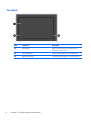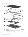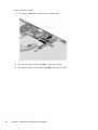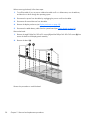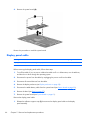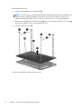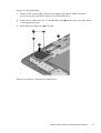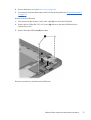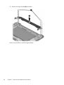
1
HP Pavilion 11 x2 PC and
HP Pro x2 410 G1 PC
Maintenance and Service Guide
IMPORTANT! This document is intended for
HP authorized service providers only.
© Copyright 2014 Hewlett-Packard
Development Company, L.P.
Bluetooth is a trademark owned by its
proprietor and used by Hewlett-Packard
Company under license. Intel, Celeron,
Core, and Pentium are U.S. registered
trademarks of Intel Corporation. Microsoft
and Windows are U.S. registered
trademarks of Microsoft Corporation. SD
Logo is a trademark of its proprietor.
The information contained herein is subject
to change without notice. The only
warranties for HP products and services are
set forth in the express warranty statements
accompanying such products and services.
Nothing herein should be construed as
constituting an additional warranty. HP shall
not be liable for technical or editorial errors
or omissions contained herein.
Third Edition: January 2014
First Edition: December 2013
Document Part Number: 731204-003
Product notice
This guide describes features that are
common to most models. Some features may
not be available on your computer.
Not all features are available in all editions
of Windows 8. This computer may require
upgraded and/or separately purchased
hardware, drivers, and/or software to take
full advantage of Windows 8 functionality.
See for http://www.microsoft.com details.
Software terms
By installing, copying, downloading, or
otherwise using any software product
preinstalled on this computer, you agree to
be bound by the terms of the HP End User
License Agreement (EULA). If you do not
accept these license terms, your sole remedy
is to return the entire unused product
(hardware and software) within 14 days for
a refund subject to the refund policy of your
place of purchase.
For any further information or to request a
full refund of the computer, please contact
your local point of sale (the seller).
Safety warning notice
WARNING! To reduce the possibility of heat-related injuries or of overheating the device, do not
place the device directly on your lap or obstruct the device air vents. Use the device only on a hard, flat
surface. Do not allow another hard surface, such as an adjoining optional printer, or a soft surface,
such as pillows or rugs or clothing, to block airflow. Also, do not allow the AC adapter to contact the
skin or a soft surface, such as pillows or rugs or clothing, during operation. The device and the AC
adapter comply with the user-accessible surface temperature limits defined by the International
Standard for Safety of Information Technology Equipment (IEC 60950).
iii
iv
Safety warning notice
Table of contents
1 Product description ........................................................................................................... 1
2 External component identification ..................................................................................... 5
Tablet ..................................................................................................................................... 5
Display components .................................................................................................. 5
Edge components ...................................................................................................... 7
Keyboard base ........................................................................................................................ 9
Top ......................................................................................................................... 9
Keys ...................................................................................................................... 10
Lights ..................................................................................................................... 11
TouchPad ............................................................................................................... 12
Left side ................................................................................................................. 13
Right side ............................................................................................................... 14
3 Illustrated parts catalog .................................................................................................. 15
Locating the serial number, product number, and model number .................................................. 15
Tablet major components ........................................................................................................ 16
Keyboard base major components ........................................................................................... 21
Miscellaneous parts ................................................................................................................ 24
Sequential part number listing .................................................................................................. 25
4 Removal and replacement preliminary requirements ...................................................... 34
Tools required ....................................................................................................................... 34
Service considerations ............................................................................................................ 34
Plastic parts ............................................................................................................ 34
Cables and connectors ............................................................................................ 34
Grounding guidelines ............................................................................................................. 35
Electrostatic discharge damage ................................................................................. 35
Packaging and transporting guidelines ....................................................... 36
Workstation guidelines .............................................................. 36
v
5 Removal and replacement procedures ............................................................................ 38
Tablet component replacement procedures ................................................................................ 38
Display enclosure .................................................................................................... 38
Sensor board .......................................................................................................... 39
Wireless antenna .................................................................................................... 41
Front-facing webcamera ........................................................................................... 43
Rear-facing webcamera ........................................................................................... 44
WLAN module ........................................................................................................ 45
Power button board ................................................................................................. 47
Volume button board ............................................................................................... 48
Vibrator module ...................................................................................................... 49
RTC battery ............................................................................................................ 50
Solid-state drive ...................................................................................................... 51
Heat sink ............................................................................................................... 53
TouchScreen board ................................................................................................. 55
Bezel ..................................................................................................................... 57
Speakers ................................................................................................................ 59
Power connector board ............................................................................................ 60
System board ......................................................................................................... 61
Display panel cable ................................................................................................ 66
Tablet battery ......................................................................................................... 67
Keyboard base component replacement procedures ................................................................... 69
Bottom cover .......................................................................................................... 69
Keyboard base battery ............................................................................................ 71
TouchPad ............................................................................................................... 73
Card reader board .................................................................................................. 74
HDMI/USB board ................................................................................................... 76
Power connector cable ............................................................................................ 77
Audio/USB board ................................................................................................... 78
Docking board ....................................................................................................... 80
Hinge assembly ...................................................................................................... 82
6 Using Setup Utility (BIOS) and HP PC Hardware Diagnostics (UEFI) .................................. 85
Starting Setup Utility (BIOS) ..................................................................................................... 85
Updating the BIOS ................................................................................................................. 85
Determining the BIOS version ................................................................................... 85
Downloading a BIOS update .................................................................................... 86
Using HP PC Hardware Diagnostics (UEFI) ................................................................................ 87
Downloading HP PC Hardware Diagnostics (UEFI) to a USB device ............................... 87
7 Specifications .................................................................................................................. 88
vi
8 Backing up, restoring, and recovering ............................................................................ 90
Creating recovery media and backups ..................................................................................... 91
Creating HP Recovery media .................................................................................... 91
Restore and recovery .............................................................................................................. 93
Recovering using HP Recovery Manager .................................................................... 93
What you need to know ............................................................................ 94
Using the HP Recovery partition (select models only) ..................................... 94
Using HP Recovery media to recover .......................................................... 95
Changing the computer boot order ............................................................. 95
Removing the HP Recovery partition .......................................................................... 95
9 Power cord set requirements .......................................................................................... 96
Requirements for all countries .................................................................................................. 96
Requirements for specific countries and regions ......................................................................... 96
10 Recycling ...................................................................................................................... 98
Index ................................................................................................................................. 99
vii
viii
1
Product description
Category
Description
Product Name
HP Pro x2 410 G1 PC
HP Pro x2 410
G1 PC
√
HP Pavilion 11 x2 PC
Processor
●
Intel® Core® i5-4202Y 1.60-GHz processor (3.00MB L3 cache, dual core, 4.5 W)
●
Intel Core i3-4012Y 1.50-GHz processor (3.00-MB
L3 cache, dual core, 4.5 W)
●
Intel Pentium® N3520 2.17-GHz (SC turbo up to
2.42-GHz) processor (1333-MHz FSB, quad core,
4.5 W)
●
Intel Pentium N3510 processor (1333-MHz FSB,
quad core, 4.5 W)
●
Intel Celeron® N2920 1.86-GHz (SC turbo up to
2.00-GHz) processor (1066-MHz FSB, 2.0-MB L2
cache, quad core, 4.5 W)
●
Intel Celeron N2910 processor (1066-MHz FSB,
quad core, 4.5 W)
HP Pavilion
11 x2 PC
√
√
√
√
Chipset
Intel soldered on chip (SOC) post controller hub (PCH)
√
Graphics
Internal Graphics: Intel HD Graphics 4200
√
√
Support for HD Decode, DX11, and HDMI
Internal Graphics: Intel HD Graphics
√
Support for HD playback, streaming, and recording @
720p 30fps
Panel
11.6-in (1366×768), high-definition (HD), IPS lightemitting diode (LED), AntiGlare, UWVA, TouchScreen
with MultiTouch enabled; 16:9 ultra-wide aspect ratio;
typical brightness: 400 nits; ultraslim (2.5-mm)
√
√
Supports low-voltage differential signaling (LVDS)
1
Category
Description
Memory
Supports DDR3L-1333-MHz (DDR3L-1600-MHz
downgrade to DDR3L-1333-MHz)
HP Pro x2 410
G1 PC
HP Pavilion
11 x2 PC
√
√
√
√
√
√
√
√
√
√
Supports DDR3L-1066-MHz (DDR3L-1600-MHz
downgrade to DDR3L-1066-MHz)
Supports up to 4096-MB maximum on-board system
memory (8 pieces of 256-MB × 16)
Storage
Supports the m2 SATA-3 (NGFF) solid-state drive
Supports the following solid-state drive configurations:
Audio and video
●
256-GB solid-state drive
●
128-GB solid-state drive
●
64-GB solid-state drive
Front-facing webcamera: 2.0-MP FHD (1080p), fixed (no
tilt)
Rear-facing webcamera: 2.0-MP FHD (1080p), fixed (no
tilt)
Single digital microphone with appropriate echocancellation and noise-suppression software
Beats Audio
Two speakers
Supports MP3, AAC, AAC+, EAAC+, OGG, and MIDI
formats
Sensors
Wireless
●
Accelerometer
●
Ambient Light Sensor
●
Digital compass
●
Gyroscope
Integrated wireless local area network (WLAN) options by
way of wireless module
One built-in WLAN antenna
Supports Miracast
Supports the Intel Dual Band Wireless-N 7260AN
802.11a/b/g/n 2×2 WiFi + BT 4.0 Combo Adapter
Supports the following WLAN modules:
2
●
Intel Wireless-N 7260BN 802.11b/g/n 2×2 WiFi
+ BT 4.0 Combo Adapter
●
Ralink RT3290LE 802.11b/g/n 1×1 WiFi and
Bluetooth 4.0 Combo Adapter
Chapter 1 Product description
√
√
Category
Description
HP Pro x2 410
G1 PC
HP Pavilion
11 x2 PC
External media
cards
HP multiformat Micro Digital Media Reader Slot with
push-push technology. Reads data from and writes data
to digital memory cards such as Secure Digital (SD).
√
√
Ports
Tablet:
√
√
√
√
●
Docking connector (supports charging/docking/
audio-out/video-out)
●
Headphone/microphone combo jack
●
Power connector
Keyboard base:
Keyboard/
pointing devices
●
Docking connector (supports charging/docking/
audio-out/video-out)
●
HDMI v1.4a supporting up to 1080p @ 60Hz
●
Headphone/microphone combo jack
●
Power connector
●
USB 3.0
●
USB 2.0
100%-size, textured, island-style keyboard
Touchpad requirements:
●
Image Sensor ClickPad
●
Multitouch gestures enabled:
◦
Touch
◦
Long touch
◦
Swipe
◦
Drag
◦
Double tap
Supports Palm rejection
Taps enabled as default
3
Category
Description
Power
requirements
Tablet and keyboard base support the following AC
adapters:
●
65-W HP Smart adapter (non-PFC, EM, 3-wire, 4.5mm)
●
45-W HP Smart adapter (non-PFC, RC, 3-wire, 4.5mm)
HP Pro x2 410
G1 PC
HP Pavilion
11 x2 PC
√
√
Tablet supports a 2-cell, 21-Wh, 2.86-Ah, Li-ion battery
Keyboard base supports a 2-cell, 28-Wh, 4.00-Ah, Li-ion
battery
4
Security
Software-based trusted platform module (TPM) solution
√
√
Operating system
Preinstalled:Microsoft® Windows 8 Standard (64-bit)
and Microsoft Windows 8 Professional (64-bit)
√
√
Serviceability
End user replaceable parts: AC adapter
√
√
Chapter 1 Product description
2
External component identification
Tablet
Display components
Item
Component
Description
(1)
WLAN antennas (2)*
Send and receive wireless signals to communicate
with WLANs.
Tablet
5
Item
Component
Description
(2)
HP TrueVision HD Webcamera (front)
Records video, captures still photographs, and allows
you to video conference and chat online using
streaming video.
Swipe from the right edge of the TouchPad or
TouchScreen to display the charms, tap Search, and
then tap the search box. Type camera, and then select
Camera from the list of applications.
– or –
From the Start screen, type camera, and then select
Camera from the list of applications.
(3)
Webcamera light (front)
On: The webcam is in use.
(4)
Ambient light sensor
The ambient light sensor automatically adjusts the
display brightness based on the lighting conditions in
your environment.
(5)
Internal microphone
Records sound.
(6)
Speakers (2)
Produce sound. Display
(7)
Windows button
Returns you to the Start screen from an open app or
the Windows desktop.
*The antennas are not visible from the outside of the computer. For optimal transmission, keep the areas immediately around
the antennas free from obstructions. For wireless regulatory notices, see the section of the Regulatory, Safety, and
Environmental Notices that applies to your country or region. To access this guide, from the Start screen, type support, and
then select the HP Support Assistant app.
6
Chapter 2 External component identification
Edge components
Item
Component
Description
(1)
Power button
●
When the computer is off, press the button to turn
on the tablet.
●
When the computer is on, press the button briefly
to initiate Sleep.
●
When the computer is in the Sleep state, press the
button briefly to exit Sleep.
CAUTION: Pressing and holding down the
power button will result in the loss of unsaved
information.
●
If the computer has stopped responding and
Windows shutdown procedures are ineffective,
press and hold the power button down for at least
5 seconds to turn off the tablet.
To learn more about your power settings, see your
power options:
Swipe from the right edge of the TouchPad or touch
screen to display the charms, tap Search, and then
tap the search box. In the search box, type power,
select Settings, and then select Power options.
– or –
From the Start screen, type power, select Power and
sleep settings, and then select Power and sleep
from the list of applications.
(2)
Alignment post connectors (2)
Align and attach the tablet to the keyboard base.
(3)
Micro SD Card Reader
Supports micro SD cards.
Tablet
7
Item
Component
Description
(4)
Audio-out (headphone)/Audio-in (microphone)
combo jack
Connects optional powered stereo speakers,
headphones, earbuds, a headset, or a television audio
cable. Also connects an optional headset microphone.
This jack does not support optional microphoneonly devices.
WARNING! To reduce the risk of personal injury,
adjust the volume before using headphones, earbuds,
or a headset. For additional safety information, see the
Regulatory, Safety and Environmental Notices. To
access this guide, from the Start screen, type
support, and then select the HP Support
Assistant app.
NOTE: When a device is connected to the jack, the
computer speakers are disabled.
NOTE: Be sure that the device cable has a 4conductor connector that supports both audio-out
(headphone) and audio-in (microphone).
(5)
Docking port/power connector
Connects the tablet to the keyboard base and connects
an AC adapter.
(6)
Power connector
Connects an AC adapter.
(7)
Volume button
Controls speaker volume on the tablet.
(8)
Webcamera (rear)
●
To increase speaker volume, press the + edge of
the button.
●
To decrease speaker volume, press the – edge of
the button.
Records video, captures still photographs, and allows
video conferences and online chat by means of
streaming video.
Swipe from the right edge of the TouchPad or
TouchScreen to display the charms, tap Search, and
then tap the search box. Type camera, and then select
Camera from the list of applications.
– or –
From the Start screen, type camera, and then select
Camera from the list of applications.
8
Chapter 2 External component identification
Keyboard base
Top
Item
Component
Description
(1)
Alignment posts
Align and attach the tablet to the keyboard base.
(2)
Docking connector
Connects the tablet to the keyboard base.
(3)
Release latch
Releases the tablet. To release the tablet, slide the
release latch to the left.
Keyboard base
9
Keys
Item
Component
Description
(1)
esc key
Displays system information when pressed in
combination with the fn key (select models only).
(2)
fn key
Executes frequently used system functions when
pressed in combination with the b key or the esc key
(select models only).
(3)
Windows key
Returns to the Start screen from an open app or the
Windows desktop.
NOTE: Pressing the Windows key again will return
to the previous screen.
(4)
Action keys
Execute frequently used system functions.
NOTE: Action keys do not display or function on the
tablet on-screen keyboard.
10
Chapter 2 External component identification
Lights
Item
Component
Description
(1)
Caps lock light
●
White: Caps lock is on.
●
Off: Caps lock is off.
●
Amber: Computer sound is off.
●
Off: Computer sound is on.
(2)
Mute light
Keyboard base
11
TouchPad
12
Item
Component
Description
(1)
TouchPad zone
Reads your finger gesture to move the pointer or
activate items on the screen.
(2)
Left TouchPad button
Functions like the left button of an external mouse.
(3)
Right TouchPad button
Functions like the right button on an external mouse.
Chapter 2 External component identification
Left side
Item
Component
Description
(1)
USB 2.0 port
Connects optional USB devices, such as a keyboard,
mouse, external drive, printer, scanner or USB hub.
(2)
Audio-out (headphone)/Audio-in (microphone)
combo jack
Connects optional powered stereo speakers,
headphones, earbuds, a headset, or a television audio
cable. Also connects an optional headset microphone.
This jack does not support optional microphoneonly devices.
WARNING! To reduce the risk of personal injury,
adjust the volume before using headphones, earbuds,
or a headset. For additional safety information, see the
Regulatory, Safety and Environmental Notices. To
access this guide, from the Start screen, type
support, and then select the HP Support
Assistant app.
NOTE: When a device is connected to the jack, the
computer speakers are disabled.
NOTE: Be sure that the device cable has a 4conductor connector that supports both audio-out
(headphone) and audio-in (microphone).
Keyboard base
13
Right side
Item
Component
Description
(1)
Memory card reader
Connects optional memory cards that store, manage,
share, or access information.
To insert the memory card, hold the card label
side up with connectors facing the slot, and then
push in the card until it is firmly seated.
●
To remove the memory card, press in on the card
and quickly release it until it pops out.
(2)
HDMI port
Connects an optional video or audio device, such as a
highdefinition television, any compatible digital or
audio component, or a high-speed HDMI device.
(3)
USB 3.0 port
Connects optional USB devices, such as a keyboard,
mouse, external drive, printer, scanner or USB hub.
(4)
AC adapter light
●
White: The AC adapter is connected and the
battery is charged.
●
Amber: The AC adapter is connected and the
battery is charging.
●
Off: The computer is using battery power.
(5)
14
●
Power connector
Chapter 2 External component identification
Connects an AC adapter.
3
Illustrated parts catalog
Locating the serial number, product number, and
model number
The serial number and product number are located on the left edge of the tablet. You may need the
information when you travel internationally or when you contact support.
Locating the serial number, product number, and model number
15
Tablet major components
Item
Component
(1)
Display enclosure (includes power button actuator and volume button actuator):
For use only on HP Pro x2 410 G1 PC computer models
For use only on HP Pavilion 11 x2 PC computer models:
16
Chapter 3 Illustrated parts catalog
Spare part number
759016-001
Item
(2)
Component
Spare part number
In flyer red finish
740182-001
In pearl white finish
740183-001
In sparkling black finish
740181-001
Sensor board (includes cable, double-sided adhesive, and microphone)
742731-001
Webcamera Kit, includes:
740191-001
(3)
Front-facing webcamera (includes bracket and cable)
(4)
Rear-facing webcamera (includes cable and double-sided adhesive)
(5)
WLAN module:
Intel Dual Band Wireless-N 7260AN 802.11a/b/g/n 2×2 WiFi + BT 4.0 Combo
Adapter for use only on HP Pro x2 410 G1 PC computer models
717381-005
For use on all computer models:
Intel Wireless-N 7260BN 802.11b/g/n 2×2 WiFi + BT 4.0 Combo Adapter
717384-005
Ralink RT3290LE 802.11b/g/n 1×1 WiFi and Bluetooth 4.0 Combo Adapter
690020-005
(6)
Vibrator module (includes cable)
741723-001
(7)
RTC battery (includes cable and double-sided adhesive)
741724-001
(8)
m2 solid-state drive:
(9)
256 GB, SATA-3
760921-001
128 GB, SATA
742736-001
64 GB, SATA
742737-001
Heat sink (includes replacement thermal material):
For use only on computer models equipped with an Intel Core processor
750355-001
For use only on computer models equipped with an Intel Pentium or
Intel Celeron processor
740186-001
(10)
Antenna Kit (includes left and right wireless antenna cables and transceivers)
741722-001
(11)
Bezel (includes power connector light pipe and regulatory label):
For use only on HP Pro x2 410 G1 PC computer models in Asia Pacific countries and
regions and Japan (APJ)
759341-001
For use only on HP Pro x2 410 G1 PC computer models in Europe, the Middle East,
and Africa (EMEA)
759340-001
For use only on HP Pro x2 410 G1 PC computer models in Latin America
759344-001
For use only on HP Pro x2 410 G1 PC computer models in North America
759339-001
For use only on HP Pro x2 410 G1 PC computer models in the People's Republic
of China
759345-001
For use only on HP Pro x2 410 G1 PC computer models in South Korea and Taiwan
759343-001
Tablet major components
17
Item
Component
Spare part number
Bezel for use only on HP Pavilion 11 x2 PC computer models equipped with the Ralink
WLAN module in the Asia Pacific regions and countries and Japan
740200-001
Bezel for use only on HP Pavilion 11 x2 PC computer models equipped with the Ralink
WLAN module in Europe, the Middle East, and Africa
740199-001
Bezel for use only on HP Pavilion 11 x2 PC computer models equipped with the Ralink
WLAN module in Latin America
742766-001
Bezel for use only on HP Pavilion 11 x2 PC computer models equipped with the Ralink
WLAN module in North America
740198-001
Bezel for use only on HP Pavilion 11 x2 PC computer models equipped with the Ralink
WLAN module in the People's Republic of China
742767-001
Bezel for use only on HP Pavilion 11 x2 PC computer models equipped with the Ralink
WLAN module in South Korea and Taiwan
740201-001
Bezel for use only on HP Pavilion 11 x2 PC computer models equipped with the Intel
WLAN module in the Asia Pacific regions and countries and Japan
745776-001
Bezel for use only on HP Pavilion 11 x2 PC computer models equipped with the Intel
WLAN module in Europe, the Middle East, and Africa
745775-001
Bezel for use only on HP Pavilion 11 x2 PC computer models equipped with the Intel
WLAN module in Latin America
745778-001
Bezel for use only on HP Pavilion 11 x2 PC computer models equipped with the Intel
WLAN module in North America
745774-001
Bezel for use only on HP Pavilion 11 x2 PC computer models equipped with the Intel
WLAN module in the People's Republic of China
745779-001
Bezel for use only on HP Pavilion 11 x2 PC computer models equipped with the Intel
WLAN module in South Korea and Taiwan
745777-001
(12)
Speaker Kit (includes left and right speakers and cables)
740193-001
(13)
Power connector board (includes cable)
742735-001
(14)
Power button board (includes cable and double-sided adhesive)
740189-001
(15)
Volume button board (includes cable and double-sided adhesive)
742732-001
(16)
TouchScreen board (includes cable and double-sided adhesive)
742734-001
(17)
System board equipped with a graphics subsystem with UMA memory (includes replacement thermal material):
For use only on HP Pro x2 410 G1 PC computer models:
18
Equipped with an Intel Core i5-4202Y 1.60-GHz processor (3.00-MB L3 cache,
dual core, 4.5 W), 4-GB of system memory, and the Windows 8 Professional
operating system
759337-601
Equipped with an Intel Core i5-4202Y 1.60-GHz processor (3.00-MB L3 cache,
dual core, 4.5 W), 4-GB of system memory, and the Windows 8 Standard
operating system
759337-501
Equipped with an Intel Core i5-4202Y 1.60-GHz processor (3.00-MB L3 cache,
dual core, 4.5 W), 4-GB of system memory, and the FreeDOS or Linux
operating system
759337-001
Chapter 3 Illustrated parts catalog
Item
Component
Spare part number
Equipped with an Intel Core i3-4012Y 1.50-GHz processor (3.00-MB L3 cache,
dual core, 4.5 W), 4-GB of system memory, and the Windows 8 Professional
operating system
759337-601
Equipped with an Intel Core i3-4012Y 1.50-GHz processor (3.00-MB L3 cache,
dual core, 4.5 W), 4-GB of system memory, and the Windows 8 Standard
operating system
759337-501
Equipped with an Intel Core i3-4012Y 1.50-GHz processor (3.00-MB L3 cache,
dual core, 4.5 W), 4-GB of system memory, and the FreeDOS or Linux
operating system
759337-001
For use only on HP Pavilion 11 x2 PC computer models:
Equipped with an Intel Core i5-4202Y 1.60-GHz processor (3.00-MB L3 cache,
dual core, 4.5 W), 4-GB of system memory, and the Windows 8 Professional
operating system
750187-601
Equipped with an Intel Core i5-4202Y 1.60-GHz processor (3.00-MB L3 cache,
dual core, 4.5 W), 4-GB of system memory, and the Windows 8 Standard
operating system
750187-501
Equipped with an Intel Core i5-4202Y 1.60-GHz processor (3.00-MB L3 cache,
dual core, 4.5 W), 4-GB of system memory, and the FreeDOS or Linux
operating system
750187-001
Equipped with an Intel Core i3-4012Y 1.50-GHz processor (3.00-MB L3 cache,
dual core, 4.5 W), 4-GB of system memory, and the Windows 8 Professional
operating system
750188-601
Equipped with an Intel Core i3-4012Y 1.50-GHz processor (3.00-MB L3 cache,
dual core, 4.5 W), 4-GB of system memory, and the Windows 8 Standard
operating system
750188-501
Equipped with an Intel Core i3-4012Y 1.50-GHz processor (3.00-MB L3 cache,
dual core, 4.5 W), 4-GB of system memory, and the FreeDOS or Linux
operating system
750188-001
Equipped with an Intel Pentium N3520 2.17-GHz (SC turbo up to 2.42-GHz)
processor (1333-MHz FSB, 2.0-MB L2 cache, quad core, 4.5 W) , 4-GB
of system memory, and the Windows 8 Professional operating system
754647-601
Equipped with an Intel Pentium N3520 2.17-GHz (SC turbo up to 2.42-GHz)
processor (1333-MHz FSB, 2.0-MB L2 cache, quad core, 4.5 W) , 4-GB
of system memory, and the Windows 8 Standard operating system
754647-501
Equipped with an Intel Pentium N3520 2.17-GHz (SC turbo up to 2.42-GHz)
processor (1333-MHz FSB, 2.0-MB L2 cache, quad core, 4.5 W) , 4-GB
of system memory, and the FreeDOS or Linux operating system
754647-001
Equipped with an Intel Pentium N3510 processor (1333-MHz FSB, quad core,
4.5 W), 4-GB of system memory, and the Windows 8 Professional operating system
741029-601
Equipped with an Intel Pentium N3510 processor (1333-MHz FSB, quad core,
4.5 W), 4-GB of system memory, and the Windows 8 Standard operating system
741029-501
Equipped with an Intel Pentium N3510 processor (1333-MHz FSB, quad core,
4.5 W), 4-GB of system memory, and the FreeDOS or Linux operating system
741029-001
Tablet major components
19
Item
20
Component
Spare part number
Equipped with an Intel Celeron N2920 1.86-GHz (SC turbo up to 2.00-GHz)
processor (1066-MHz FSB, 2.0-MB L2 cache, quad core, 4.5 W) , 4-GB
of system memory, and the Windows 8 Professional operating system
754648-601
Equipped with an Intel Celeron N2920 1.86-GHz (SC turbo up to 2.00-GHz)
processor (1066-MHz FSB, 2.0-MB L2 cache, quad core, 4.5 W) , 4-GB
of system memory, and the Windows 8 Standard operating system
754648-501
Equipped with an Intel Celeron N2920 1.86-GHz (SC turbo up to 2.00-GHz)
processor (1066-MHz FSB, 2.0-MB L2 cache, quad core, 4.5 W) , 4-GB
of system memory, and the Windows 7, FreeDOS or Linux operating system
754648-001
Equipped with an Intel Celeron N2920 1.86-GHz (SC turbo up to 2.00-GHz)
processor (1066-MHz FSB, 2.0-MB L2 cache, quad core, 4.5 W) , 2-GB
of system memory, and the Windows 8 Professional operating system
754649-601
Equipped with an Intel Celeron N2920 1.86-GHz (SC turbo up to 2.00-GHz)
processor (1066-MHz FSB, 2.0-MB L2 cache, quad core, 4.5 W) , 2-GB
of system memory, and the Windows 8 Standard operating system
754649-501
Equipped with an Intel Celeron N2920 1.86-GHz (SC turbo up to 2.00-GHz)
processor (1066-MHz FSB, 2.0-MB L2 cache, quad core, 4.5 W) , 2-GB
of system memory, and the FreeDOS or Linux operating system
754649-001
Equipped with an Intel Celeron N2910 processor (1066-MHz FSB, quad core,
4.5 W), 4-GB of system memory, and the Windows 8 Professional operating system
741030-601
Equipped with an Intel Celeron N2910 processor (1066-MHz FSB, quad core,
4.5 W), 4-GB of system memory, and the Windows 8 Standard operating system
741030-501
Equipped with an Intel Celeron N2910 processor (1066-MHz FSB, quad core,
4.5 W), 4-GB of system memory, and the FreeDOS or Linux operating system
741030-001
Equipped with an Intel Celeron N2910 processor (1066-MHz FSB, quad core,
4.5 W), 2-GB of system memory, and the Windows 8 Professional operating system
741031-601
Equipped with an Intel Celeron N2910 processor (1066-MHz FSB, quad core,
4.5 W), 2-GB of system memory, and the Windows 8 Standard operating system
741031-501
Equipped with an Intel Celeron N2910 processor (1066-MHz FSB, quad core,
4.5 W), 2-GB of system memory, and the FreeDOS or Linux operating system
741031-001
(18)
Display panel cable (includes adhesive support strips)
740197-001
(19)
2-cell, 21-Wh, 2.86-Ah, Li-ion battery (for use only in the tablet, includes cable)
722232-005
(20)
Display panel assembly (11.6-inch, AG, HD, UWVA, LED TouchScreen)
740194-001
Chapter 3 Illustrated parts catalog
Keyboard base major components
Item
Component
(1)
Hinge assembly (includes alignment posts, cables, docking connector, and release latch):
For use only on HP Pro x2 410 G1 PC keyboard bases
Spare part number
759019-001
For use only on HP Pavilion 11 x2 PC keyboard bases:
(2)
(3)
In flyer red finish
740204-001
In pearl white finish
740205-001
In sparkling white finish
740203-001
TouchPad (includes cable):
For use only on HP Pro x2 410 G1 PC keyboard bases
759689-001
For use only on HP Pavilion 11 x2 PC keyboard bases
740190-001
Keyboard/top cover (includes keyboard cable):
Keyboard base major components
21
Item
Component
Spare part number
For use only on HP Pro x2 410 G1 PC keyboard bases:
For use in Belgium
759346-A41
For use in Canada
759346-DB1
For use in the Czech Republic and Slovakia
759346-FL1
For use in Denmark, Finland, and Norway
759346-DH1
For use in France
759346-041
For use in Germany
759346-051
For use in Greece
759346-151
For use in Italy
759346-061
For use in Latin America
759346-161
For use in the Netherlands
759346-B31
For use in Portugal
759346-131
For use in Russia
759346-251
For use in Saudi Arabia
759346-171
For use in South Korea
759346-AD1
For use in Spain
759346-071
For use in Switzerland
759346-BG1
For use in Taiwan
759346-AB1
For use in Thailand
759346-281
For use in Turkey
759346-141
For use in the United Kingdom and Singapore
759346-031
For use in the United States
759346-001
For use only on HP Pavilion 11 x2 PC keyboard bases:
22
For use in Belgium
740184-A41
For use in Canada
740184-DB1
For use in the Czech Republic and Slovakia
740184-FL1
For use in Denmark, Finland, and Norway
740184-DH1
For use in France
740184-051
For use in Germany
740184-041
For use in Greece
740184-151
For use in Italy
740184-061
For use in Japan
740184-291
Chapter 3 Illustrated parts catalog
Item
Component
Spare part number
For use in Latin America
740184-161
For use in the Netherlands
740184-B31
For use in Portugal
740184-131
For use in Russia
740184-251
For use in Saudi Arabia
740184-171
For use in South Korea
740184-AD1
For use in Spain
740184-071
For use in Switzerland
740184-BG1
For use in Taiwan
740184-AB1
For use in Thailand
740184-281
For use in Turkey
740184-141
For use in the United Kingdom and Singapore
740184-031
For use in the United States
740184-001
(4)
Docking board
740206-001
(5)
Power connector cable
740188-001
(6)
Audio/USB board (includes audio-out/audio-in combo jack and USB 2.0 port)
742733-001
(7)
HDMI/USB board (includes HDMI port and USB 3.0 port)
740209-001
(8)
Card reader board (includes cable)
740202-001
(9)
2-cell, 28-Wh, 4.00-Ah, Li-ion battery (for use only in the keyboard base,
includes cable)
726596-005
(10)
Bottom cover (includes rubber padding, shielding, and 5 rubber feet):
For use only on HP Pro x2 410 G1 PC keyboard bases:
For use only on keyboard bases using a 65-W AC adapter
759017-001
For use only on keyboard bases using a 45-W AC adapter in South Korea
and Taiwan
759018-001
For use only on HP Pavilion 11 x2 PC keyboard bases:
In flyer red finish
740195-001
In flyer red finish
757225-001
In pearl white finish
740196-001
In sparkling black finish
757224-001
In sparkling black finish
740185-001
Rubber Feet Kit (not illustrated, includes keyboard base bottom cover rubber feet)
Keyboard base major components
23
Item
Component
Spare part number
For use only on HP Pro x2 410 G1 PC keyboard bases
759338-001
For use only on HP Pavilion 11 x2 PC keyboard bases
740207-001
Miscellaneous parts
Component
Spare part number
AC adapter:
65-W HP Smart adapter (non-PFC, EM, 3-wire, 4.5-mm) for use on all computer models
714657-001
45-W HP Smart adapter (non-PFC, RC, 3-wire, 4.5-mm) for use on all computer models
721092-001
45-W HP Smart adapter (non-PFC, RC, non-slim, 3-wire, 4.5-mm) for use only on
HP Pavilion 11 x2 PC computer models
741727-001
HP HDMI-to-VGA adapter
701943-001
HP RJ-45-to-USB adapter dongle
539614-001
Power cord (3-pin, black, 1.83-m):
For use in Argentina on all computer models
490371-D01
For use in Australia on all computer models
490371-011
For use in Denmark on all computer models
490371-081
For use in Europe on all computer models
490371-021
For use in India on all computer models
490371-D61
For use in Italy on all computer models
490371-061
For use in Japan only on HP Pavilion 11 x2 PC computer models
490371-291
For use in North America on all computer models
490371-001
For use in the People's Republic of China on all computer models
490371-AA1
For use in South Korea on all computer models
490371-AD1
For use in Switzerland on all computer models
490371-111
For use in Taiwan on all computer models
490371-AB1
For use in Thailand on all computer models
490371-201
For use in the United Kingdom and Singapore on all computer models
490371-031
Rubber Feet Kit (includes keyboard base bottom cover rubber feet):
24
For use only on HP Pro x2 410 G1 PC computer models
759338-001
For use only on HP Pavilion 11 x2 PC computer models
740207-001
Screw Kit
740208-001
Chapter 3 Illustrated parts catalog
Sequential part number listing
Spare part number
Description
490371-001
Power cord for use on all computer models in North America (3-pin, black, 1.83-m)
490371-011
Power cord for use on all computer models in Australia (3-pin, black, 1.83-m)
490371-021
Power cord for use on all computer models in Europe (3-pin, black, 1.83-m)
490371-031
Power cord for use on all computer models in the United Kingdom and Singapore (3-pin, black,
1.83-m)
490371-061
Power cord for use on all computer models in Italy (3-pin, black, 1.83-m)
490371-081
Power cord for use on all computer models in Denmark (3-pin, black, 1.83-m)
490371-111
Power cord for use on all computer models in Switzerland (3-pin, black, 1.83-m)
490371-201
Power cord for use on all computer models in Thailand (3-pin, black, 1.83-m)
490371-291
Power cord for use only on HP Pavilion 11 x2 PC computer models in Japan (3-pin, black, 1.83-m)
490371-AA1
Power cord for use on all computer models in the People's Republic of China (3-pin, black, 1.83-m)
490371-AB1
Power cord for use on all computer models in Taiwan (3-pin, black, 1.83-m)
490371-AD1
Power cord for use on all computer models in South Korea (3-pin, black, 1.83-m)
490371-D01
Power cord for use on all computer models in Argentina (3-pin, black, 1.83-m)
490371-D61
Power cord for use on all computer models in India (3-pin, black, 1.83-m)
539614-001
RJ-45-to-USB adapter dongle
690020-005
Ralink RT3290LE 802.11b/g/n 1×1 WiFi and Bluetooth 4.0 Combo Adapter for use on all
computer models
701943-001
HDMI-to-VGA adapter
714657-001
65-W HP Smart adapter for use on all computer models (non-PFC, EM, 3-wire, 4.5-mm)
717381-005
Intel Dual Band Wireless-N 7260AN 802.11a/b/g/n 2×2 WiFi + BT 4.0 Combo Adapter for use
only on HP Pro x2 410 G1 PC computer models
717384-005
Intel Wireless-N 7260BN 802.11b/g/n 2×2 WiFi + BT 4.0 Combo Adapter for use on all
computer models
721092-001
45-W HP Smart adapter for use on all computer models (non-PFC, RC, 3-wire, 4.5-mm)
722232-005
2-cell, 21-Wh, 2.86-Ah, Li-ion battery for use only in the tablet (includes cable)
726596-005
2-cell, 28-Wh, 4.00-Ah, Li-ion battery for use only in the keyboard/base (includes cable)
740181-001
Display enclosure in sparkling black finish for use only on HP Pavilion 11 x2 PC computer models
(includes power button actuator and volume button actuator)
740182-001
Display enclosure in flyer red finish for use only on HP Pavilion 11 x2 PC computer models
(includes power button actuator and volume button actuator)
740183-001
Display enclosure in pearl white finish for use only on HP Pavilion 11 x2 PC computer models
(includes power button actuator and volume button actuator)
Sequential part number listing
25
26
Spare part number
Description
740184-001
Keyboard/top cover with TouchPad for use in the United States only on HP Pavilion 11 x2 PC
computer models (includes keyboard cable and TouchPad cable)
740184-031
Keyboard/top cover with TouchPad for use in the United Kingdom and Singapore only on
HP Pavilion 11 x2 PC computer models (includes keyboard cable and TouchPad cable)
740184-041
Keyboard/top cover with TouchPad for use in Germany only on HP Pavilion 11 x2 PC computer
models (includes keyboard cable and TouchPad cable)
740184-051
Keyboard/top cover with TouchPad for use in France only on HP Pavilion 11 x2 PC computer
models (includes keyboard cable and TouchPad cable)
740184-061
Keyboard/top cover with TouchPad for use in Italy only on HP Pavilion 11 x2 PC computer models
(includes keyboard cable and TouchPad cable)
740184-071
Keyboard/top cover with TouchPad for use in Spain only on HP Pavilion 11 x2 PC computer
models (includes keyboard cable and TouchPad cable)
740184-131
Keyboard/top cover with TouchPad for use in Portugal only on HP Pavilion 11 x2 PC computer
models (includes keyboard cable and TouchPad cable)
740184-141
Keyboard/top cover with TouchPad for use in Turkey only on HP Pavilion 11 x2 PC computer
models (includes keyboard cable and TouchPad cable)
740184-151
Keyboard/top cover with TouchPad for use in Greece only on HP Pavilion 11 x2 PC computer
models (includes keyboard cable and TouchPad cable)
740184-161
Keyboard/top cover with TouchPad for use in Latin America only on HP Pavilion 11 x2 PC
computer models (includes keyboard cable and TouchPad cable)
740184-171
Keyboard/top cover with TouchPad for use in Saudi Arabia only on HP Pavilion 11 x2 PC
computer models (includes keyboard cable and TouchPad cable)
740184-251
Keyboard/top cover with TouchPad for use in Russia only on HP Pavilion 11 x2 PC computer
models (includes keyboard cable and TouchPad cable)
740184-281
Keyboard/top cover with TouchPad for use in Thailand only on HP Pavilion 11 x2 PC computer
models (includes keyboard cable and TouchPad cable)
740184-291
Keyboard/top cover with TouchPad for use in Japan only on HP Pavilion 11 x2 PC computer
models (includes keyboard cable and TouchPad cable)
740184-A41
Keyboard/top cover with TouchPad for use in Belgium only on HP Pavilion 11 x2 PC computer
models (includes keyboard cable and TouchPad cable)
740184-AB1
Keyboard/top cover with TouchPad for use in Taiwan only on HP Pavilion 11 x2 PC computer
models (includes keyboard cable and TouchPad cable)
740184-AD1
Keyboard/top cover with TouchPad for use in South Korea only on HP Pavilion 11 x2 PC computer
models (includes keyboard cable and TouchPad cable)
740184-B31
Keyboard/top cover with TouchPad for use in the Netherlands only on HP Pavilion 11 x2 PC
computer models (includes keyboard cable and TouchPad cable)
740184-BG1
Keyboard/top cover with TouchPad for use in Switzerland only on HP Pavilion 11 x2 PC computer
models (includes keyboard cable and TouchPad cable)
740184-DB1
Keyboard/top cover with TouchPad for use in Canada only on HP Pavilion 11 x2 PC computer
models (includes keyboard cable and TouchPad cable)
Chapter 3 Illustrated parts catalog
Spare part number
Description
740184-DH1
Keyboard/top cover with TouchPad for use in Denmark, Finland, and Norway only on HP Pavilion
11 x2 PC computer models (includes keyboard cable and TouchPad cable)
740184-FL1
Keyboard/top cover with TouchPad for use in the Czech Republic and Slovakia only on HP Pavilion
11 x2 PC computer models (includes keyboard cable and TouchPad cable)
740185-001
Bottom cover in sparkling black trim for use only on HP Pavilion 11 x2 PC computer models
(includes rubber padding, shielding, and 5 rubber feet)
740186-001
Heat sink for use only on HP Pavilion 11 x2 PC computer models equipped with Intel Pentium or
Intel Celeron processors (includes replacement thermal material)
740188-001
Power connector cable
740189-001
Power button board (includes cable and double-sided adhesive)
740190-001
TouchPad for use only on HP Pavilion 11 x2 PC computer models (includes cable)
740191-001
Webcamera Kit (includes front-facing webcamera, bracket and cable and rear-facing webcamera
and cable)
740193-001
Speaker Kit (includes left and right speakers and cables)
740194-001
11.6-inch, AG, HD, UWVA, LED TouchScreen display panel assembly
740195-001
Bottom cover in flyer red finish for use only on HP Pavilion 11 x2 PC computer models
(includes rubber padding, shielding, and 5 rubber feet)
740196-001
Bottom cover in pearl white finish for use only on HP Pavilion 11 x2 PC computer models
(includes rubber padding, shielding, and 5 rubber feet)
740197-001
Display panel cable (includes adhesive support strips)
740198-001
Bezel for use only on computer models equipped with the Ralink WLAN module in North America
(includes power connector light pipe and regulatory label)
740199-001
Bezel for use only on computer models equipped with the Ralink WLAN module in Europe,
the Middle East, and Africa (includes power connector light pipe and regulatory label)
740200-001
Bezel for use only on computer models equipped with the Ralink WLAN module in the Asia Pacific
regions and countries and Japan (includes power connector light pipe and regulatory label)
740201-001
Bezel for use only on computer models equipped with the Ralink WLAN module in the South Korea
and Taiwan (includes power connector light pipe and regulatory label)
740202-001
Card reader board (includes cable)
740203-001
Hinge assembly in sparkling black finish for use only on HP Pavilion 11 x2 PC computer models
(includes alignment posts, cables, docking connector, and release latch)
740204-001
Hinge assembly in flyer red finish for use only on HP Pavilion 11 x2 PC computer models
(includes alignment posts, cables, docking connector, and release latch)
740205-001
Hinge assembly in pearl white finish for use only on HP Pavilion 11 x2 PC computer models
(includes alignment posts, cables, docking connector, and release latch)
740206-001
Docking board
740207-001
Rubber Feet Kit for use only on HP Pavilion 11 x2 PC computer models (includes keyboard base
bottom cover rubber feet)
740208-001
Screw Kit
Sequential part number listing
27
28
Spare part number
Description
740209-001
HDMI/USB board (includes HDMI port and USB 3.0 port)
741029-001
System board equipped with an Intel Pentium N3510 processor for use only on HP Pavilion
11 x2 PC computer models (1333-MHz FSB, quad core, 4.5 W), 4-GB of system memory, a
graphics subsystem with UMA memory, and the FreeDOS or Linux operating system
(includes replacement thermal material)
741029-501
System board equipped with an Intel Pentium N3510 processor for use only on HP Pavilion
11 x2 PC computer models (1333-MHz FSB, quad core, 4.5 W), 4-GB of system memory, a
graphics subsystem with UMA memory, and the Windows 8 Standard operating system
(includes replacement thermal material)
741029-601
System board equipped with an Intel Pentium N3510 processor for use only on HP Pavilion
11 x2 PC computer models (1333-MHz FSB, quad core, 4.5 W), 4-GB of system memory, a
graphics subsystem with UMA memory, and the Windows 8 Professional operating system
(includes replacement thermal material)
741030-001
System board equipped with an Intel Celeron N2910 processor for use only on HP Pavilion
11 x2 PC computer models (1066-MHz FSB, quad core, 4.5 W), 4-GB of system memory, a
graphics subsystem with UMA memory, and the FreeDOS or Linux operating system
(includes replacement thermal material)
741030-501
System board equipped with an Intel Celeron N2910 processor for use only on HP Pavilion
11 x2 PC computer models (1066-MHz FSB, quad core, 4.5 W), 4-GB of system memory, a
graphics subsystem with UMA memory, and the Windows 8 Standard operating system
(includes replacement thermal material)
741030-601
System board equipped with an Intel Celeron N2910 processor for use only on HP Pavilion
11 x2 PC computer models (1066-MHz FSB, quad core, 4.5 W), 4-GB of system memory, a
graphics subsystem with UMA memory, and the Windows 8 Professional operating system
(includes replacement thermal material)
741031-001
System board equipped with an Intel Celeron N2910 processor for use only on HP Pavilion
11 x2 PC computer models (1066-MHz FSB, quad core, 4.5 W), 2-GB of system memory, a
graphics subsystem with UMA memory, and the FreeDOS or Linux operating system
(includes replacement thermal material)
741031-501
System board equipped with an Intel Celeron N2910 processor for use only on HP Pavilion
11 x2 PC computer models (1066-MHz FSB, quad core, 4.5 W), 2-GB of system memory, a
graphics subsystem with UMA memory, and the Windows 8 Standard operating system
(includes replacement thermal material)
741031-601
System board equipped with an Intel Celeron N2910 processor for use only on HP Pavilion
11 x2 PC computer models (1066-MHz FSB, quad core, 4.5 W), 2-GB of system memory, a
graphics subsystem with UMA memory, and the Windows 8 Professional operating system
(includes replacement thermal material)
741722-001
Antenna Kit (includes left and right wireless antenna cables and transceivers)
741723-001
Vibrator module (includes cable)
741724-001
RTC battery (includes cable and double-sided adhesive)
741727-001
45-W HP Smart adapter for use only on HP Pavilion 11 x2 PC computer models (non-PFC, non-slim,
RC, 3-wire, 4.5-mm)
742731-001
Sensor board (includes cable, double-sided adhesive, and microphone)
742732-001
Volume button board (includes cable and double-sided adhesive)
Chapter 3 Illustrated parts catalog
Spare part number
Description
742733-001
Audio/USB board (includes audio-out/audio-in combo jack and USB 2.0 port)
742734-001
TouchScreen board (includes cable and double-sided adhesive)
742735-001
Power connector board (includes cable)
742736-001
128-GB m2 SATA solid-state drive
742737-001
64-GB m2 SATA solid-state drive
742766-001
Bezel for use only on computer models equipped with the Ralink WLAN module in Latin America
(includes power connector light pipe and regulatory label)
742767-001
Bezel for use only on computer models equipped with the Ralink WLAN module in the People's
Republic of China (includes power connector light pipe and regulatory label)
745774-001
Bezel for use only on computer models equipped with an Intel WLAN module in North America
(includes power connector light pipe and regulatory label)
745775-001
Bezel for use only on computer models equipped with an Intel WLAN module in Europe, the Middle
East, and Africa (includes power connector light pipe and regulatory label)
745776-001
Bezel for use only on computer models equipped with an Intel WLAN module in the Asia Pacific
regions and countries and Japan (includes power connector light pipe and regulatory label)
745777-001
Bezel for use only on computer models equipped with an Intel WLAN module in South Korea and
Taiwan (includes power connector light pipe and regulatory label)
745778-001
Bezel for use only on computer models equipped with an Intel WLAN module in Latin America
(includes power connector light pipe and regulatory label)
745779-001
Bezel for use only on computer models equipped with an Intel WLAN module in the People's
Republic of China (includes power connector light pipe and regulatory label)
750187-001
System board equipped with an Intel Core i5-4202Y 1.60-GHz processor for use only on
HP Pavilion 11 x2 PC computer models (3.00-MB L3 cache, dual core, 4.5 W), 4-GB
of system memory, and the FreeDOS or Linux operating system (includes replacement
thermal material)
750187-501
System board equipped with an Intel Core i5-4202Y 1.60-GHz processor for use only on
HP Pavilion 11 x2 PC computer models (3.00-MB L3 cache, dual core, 4.5 W), 4-GB
of system memory, and the Windows 8 Standard operating system (includes replacement
thermal material)
750187-601
System board equipped with an Intel Core i5-4202Y 1.60-GHz processor for use only on
HP Pavilion 11 x2 PC computer models (3.00-MB L3 cache, dual core, 4.5 W), 4-GB
of system memory, and the Windows 8 Professional operating system (includes replacement
thermal material)
750188-001
System board equipped with an Intel Core i3-4012Y 1.50-GHz processor for use only on
HP Pavilion 11 x2 PC computer models (3.00-MB L3 cache, dual core, 4.5 W), 4-GB
of system memory, and the FreeDOS or Linux operating system (includes replacement
thermal material)
750188-501
System board equipped with an Intel Core i3-4012Y 1.50-GHz processor for use only on
HP Pavilion 11 x2 PC computer models (3.00-MB L3 cache, dual core, 4.5 W), 4-GB
of system memory, and the Windows 8 Standard operating system (includes replacement
thermal material)
Sequential part number listing
29
30
Spare part number
Description
750188-601
System board equipped with an Intel Core i3-4012Y 1.50-GHz processor for use only on
HP Pavilion 11 x2 PC computer models (3.00-MB L3 cache, dual core, 4.5 W), 4-GB
of system memory, and the Windows 8 Professional operating system (includes replacement
thermal material)
750355-001
Heat sink for use on all computer models equipped with an Intel Core processor
(includes replacement thermal material)
754647-001
System board equipped with an Intel Pentium N3520 2.17-GHz (SC turbo up to 2.42-GHz)
processor for use only on HP Pavilion 11 x2 PC computer models (1333-MHz FSB, 2.0-MB L2
cache, quad core, 4.5 W) , 4-GB of system memory, and the FreeDOS or Linux operating system
(includes replacement thermal material)
754647-501
System board equipped with an Intel Pentium N3520 2.17-GHz (SC turbo up to 2.42-GHz)
processor for use only on HP Pavilion 11 x2 PC computer models (1333-MHz FSB, 2.0-MB L2
cache, quad core, 4.5 W) , 4-GB of system memory, and the Windows 8 Standard
operating system (includes replacement thermal material)
754647-601
System board equipped with an Intel Pentium N3520 2.17-GHz (SC turbo up to 2.42-GHz)
processor for use only on HP Pavilion 11 x2 PC computer models (1333-MHz FSB, 2.0-MB L2
cache, quad core, 4.5 W) , 4-GB of system memory, and the Windows 8 Professional
operating system (includes replacement thermal material)
754648-001
System board equipped with an Intel Celeron N2920 1.86-GHz (SC turbo up to 2.00-GHz)
processor for use only on HP Pavilion 11 x2 PC computer models (1066-MHz FSB, 2.0-MB L2
cache, quad core, 4.5 W) , 4-GB of system memory, and the FreeDOS or Linux operating system
(includes replacement thermal material)
754648-501
System board equipped with an Intel Celeron N2920 1.86-GHz (SC turbo up to 2.00-GHz)
processor for use only on HP Pavilion 11 x2 PC computer models (1066-MHz FSB, 2.0-MB L2
cache, quad core, 4.5 W) , 4-GB of system memory, and the Windows 8 Standard
operating system (includes replacement thermal material)
754648-601
System board equipped with an Intel Celeron N2920 1.86-GHz (SC turbo up to 2.00-GHz)
processor for use only on HP Pavilion 11 x2 PC computer models (1066-MHz FSB, 2.0-MB L2
cache, quad core, 4.5 W) , 4-GB of system memory, and the Windows 8 Professional
operating system (includes replacement thermal material)
754649-001
System board equipped with an Intel Celeron N2920 1.86-GHz (SC turbo up to 2.00-GHz)
processor for use only on HP Pavilion 11 x2 PC computer models (1066-MHz FSB, 2.0-MB L2
cache, quad core, 4.5 W) , 2-GB of system memory, and the FreeDOS or Linux operating system
(includes replacement thermal material)
754649-501
System board equipped with an Intel Celeron N2920 1.86-GHz (SC turbo up to 2.00-GHz)
processor for use only on HP Pavilion 11 x2 PC computer models (1066-MHz FSB, 2.0-MB L2
cache, quad core, 4.5 W) , 2-GB of system memory, and the Windows 8 Standard
operating system (includes replacement thermal material)
754649-601
System board equipped with an Intel Celeron N2920 1.86-GHz (SC turbo up to 2.00-GHz)
processor for use only on HP Pavilion 11 x2 PC computer models (1066-MHz FSB, 2.0-MB L2
cache, quad core, 4.5 W) , 2-GB of system memory, and the Windows 8 Professional
operating system (includes replacement thermal material)
757224-001
Bottom cover in sparkling black finish for use only on HP Pavilion 11 x2 PC computer models
(includes rubber padding, shielding, and 5 rubber feet)
757225-001
Bottom cover in flyer red finish for use only on HP Pavilion 11 x2 PC computer models
(includes rubber padding, shielding, and 5 rubber feet)
Chapter 3 Illustrated parts catalog
Spare part number
Description
759016-001
Display enclosure for use only on HP Pro x2 410 G1 PC computer models (includes power button
actuator and volume button actuator)
759017-001
Bottom cover for use only on HP Pro x2 410 G1 PC keyboard bases using a 65-W AC adapter
(includes rubber padding, shielding, and 5 rubber feet)
759018-001
Bottom cover for use only on HP Pro x2 410 G1 PC keyboard bases using a 45-W AC adapter in
South Korea and Taiwan (includes rubber padding, shielding, and 5 rubber feet)
759019-001
Hinge assembly for use only on HP Pro x2 410 G1 PC computer models (includes alignment posts,
cables, docking connector, and release latch)
759336-001
System board equipped with an Intel Core i5-4202Y 1.60-GHz processor for use only on HP Pro x2
410 G1 PC computer models (3.00-MB L3 cache, dual core, 4.5 W), 4-GB of system memory, and
the FreeDOS or Linux operating system (includes replacement thermal material)
759336-501
System board equipped with an Intel Core i5-4202Y 1.60-GHz processor for use only on HP Pro x2
410 G1 PC computer models (3.00-MB L3 cache, dual core, 4.5 W), 4-GB of system memory, and
the Windows 8 Standard operating system (includes replacement thermal material)
759336-601
System board equipped with an Intel Core i5-4202Y 1.60-GHz processor for use only on HP Pro x2
410 G1 PC computer models (3.00-MB L3 cache, dual core, 4.5 W), 4-GB of system memory, and
the Windows 8 Professional operating system (includes replacement thermal material)
759337-001
System board equipped with an Intel Core i3-4012Y 1.50-GHz processor for use only on HP Pro x2
410 G1 PC computer models (3.00-MB L3 cache, dual core, 4.5 W), 4-GB of system memory, and
the FreeDOS or Linux operating system (includes replacement thermal material)
759337-501
System board equipped with an Intel Core i3-4012Y 1.50-GHz processor for use only on HP Pro x2
410 G1 PC computer models (3.00-MB L3 cache, dual core, 4.5 W), 4-GB of system memory, and
the Windows 8 Standard operating system (includes replacement thermal material)
759337-601
System board equipped with an Intel Core i3-4012Y 1.50-GHz processor for use only on HP Pro x2
410 G1 PC computer models (3.00-MB L3 cache, dual core, 4.5 W), 4-GB of system memory, and
the Windows 8 Professional operating system (includes replacement thermal material)
759338-001
Rubber Feet Kit for use only on HP Pro x2 410 G1 PC computer models (includes keyboard base
bottom cover rubber feet)
759339-001
Bezel for use only on HP Pro x2 410 G1 PC computer models in North America (includes power
connector light pipe and regulatory label)
759340-001
Bezel for use only on HP Pro x2 410 G1 PC computer models in Europe, the Middle East, and
Africa (EMEA; includes power connector light pipe and regulatory label)
759341-001
Bezel for use only on HP Pro x2 410 G1 PC computer models in Asia Pacific countries and regions
and Japan (APJ; includes power connector light pipe and regulatory label)
759343-001
Bezel for use only on HP Pro x2 410 G1 PC computer models in South Korea and Taiwan
(includes power connector light pipe and regulatory label)
759344-001
Bezel for use only on HP Pro x2 410 G1 PC computer models in Latin America (includes power
connector light pipe and regulatory label)
759345-001
Bezel for use only on HP Pro x2 410 G1 PC computer models in the People's Republic of China
(includes power connector light pipe and regulatory label)
759346-001
Keyboard/top cover with TouchPad for use in the United States only on HP Pro x2 410 G1 PC
computer models (includes keyboard cable and TouchPad cable)
Sequential part number listing
31
32
Spare part number
Description
759346-031
Keyboard/top cover with TouchPad for use in the United Kingdom and Singapore only on
HP Pro x2 410 G1 PC computer models (includes keyboard cable and TouchPad cable)
759346-041
Keyboard/top cover with TouchPad for use in France only on HP Pro x2 410 G1 PC computer
models (includes keyboard cable and TouchPad cable)
759346-051
Keyboard/top cover with TouchPad for use in Germany only on HP Pro x2 410 G1 PC computer
models (includes keyboard cable and TouchPad cable)
759346-061
Keyboard/top cover with TouchPad for use in Italy only on HP Pro x2 410 G1 PC computer models
(includes keyboard cable and TouchPad cable)
759346-071
Keyboard/top cover with TouchPad for use in Spain only on HP Pro x2 410 G1 PC computer
models (includes keyboard cable and TouchPad cable)
759346-131
Keyboard/top cover with TouchPad for use in Portugal only on HP Pro x2 410 G1 PC computer
models (includes keyboard cable and TouchPad cable)
759346-141
Keyboard/top cover with TouchPad for use in Turkey only on HP Pro x2 410 G1 PC computer
models (includes keyboard cable and TouchPad cable)
759346-151
Keyboard/top cover with TouchPad for use in Greece only on HP Pro x2 410 G1 PC computer
models (includes keyboard cable and TouchPad cable)
759346-161
Keyboard/top cover with TouchPad for use in Latin America only on HP Pro x2 410 G1 PC
computer models (includes keyboard cable and TouchPad cable)
759346-171
Keyboard/top cover with TouchPad for use in Saudi Arabia only on HP Pro x2 410 G1 PC
computer models (includes keyboard cable and TouchPad cable)
759346-251
Keyboard/top cover with TouchPad for use in Russia only on HP Pro x2 410 G1 PC computer
models (includes keyboard cable and TouchPad cable)
759346-281
Keyboard/top cover with TouchPad for use in Thailand only on HP Pro x2 410 G1 PC computer
models (includes keyboard cable and TouchPad cable)
759346-A41
Keyboard/top cover with TouchPad for use in Belgium only on HP Pro x2 410 G1 PC computer
models (includes keyboard cable and TouchPad cable)
759346-AB1
Keyboard/top cover with TouchPad for use in Taiwan only on HP Pro x2 410 G1 PC computer
models (includes keyboard cable and TouchPad cable)
759346-AD1
Keyboard/top cover with TouchPad for use in South Korea only on HP Pro x2 410 G1 PC computer
models (includes keyboard cable and TouchPad cable)
759346-B31
Keyboard/top cover with TouchPad for use in the Netherlands only on HP Pro x2 410 G1 PC
computer models (includes keyboard cable and TouchPad cable)
759346-BG1
Keyboard/top cover with TouchPad for use in Switzerland only on HP Pro x2 410 G1 PC computer
models (includes keyboard cable and TouchPad cable)
759346-DB1
Keyboard/top cover with TouchPad for use in Canada only on HP Pro x2 410 G1 PC computer
models (includes keyboard cable and TouchPad cable)
759346-DH1
Keyboard/top cover with TouchPad for use in Denmark, Finland, and Norway only on HP Pro x2
410 G1 PC computer models (includes keyboard cable and TouchPad cable)
759346-FL1
Keyboard/top cover with TouchPad for use in the Czech Republic and Slovakia only on HP Pro x2
410 G1 PC computer models (includes keyboard cable and TouchPad cable)
Chapter 3 Illustrated parts catalog
Spare part number
Description
759689-001
TouchPad for use only on HP Pro x2 410 G1 PC computer models (includes cable)
760921-001
256-GB m2 SATA-3 solid-state drive
Sequential part number listing
33
4
Removal and replacement
preliminary requirements
Tools required
You will need the following tools to complete the removal and replacement procedures:
●
Magnetic screw driver
●
Phillips P0 screw driver
●
Plastic case utility tool
Service considerations
The following sections include some of the considerations that you must keep in mind during
disassembly and assembly procedures.
NOTE: As you remove each subassembly from the tablet, place the subassembly (and all
accompanying screws) away from the work area to prevent damage.
Plastic parts
CAUTION: Using excessive force during disassembly and reassembly can damage plastic parts.
Use care when handling the plastic parts. Apply pressure only at the points designated in the
maintenance instructions.
Cables and connectors
CAUTION: When servicing the tablet, be sure that cables are placed in their proper locations during
the reassembly process. Improper cable placement can damage the tablet.
Cables must be handled with extreme care to avoid damage. Apply only the tension required to unseat
or seat the cables during removal and insertion. Handle cables by the connector whenever possible. In
all cases, avoid bending, twisting, or tearing cables. Be sure that cables are routed in such a way that
they cannot be caught or snagged by parts being removed or replaced. Handle flex cables with
extreme care; these cables tear easily.
34
Chapter 4 Removal and replacement preliminary requirements
Grounding guidelines
Electrostatic discharge damage
Electronic components are sensitive to electrostatic discharge (ESD). Circuitry design and structure
determine the degree of sensitivity. Networks built into many integrated circuits provide some
protection, but in many cases, ESD contains enough power to alter device parameters or melt
silicon junctions.
A discharge of static electricity from a finger or other conductor can destroy static-sensitive devices or
microcircuitry. Even if the spark is neither felt nor heard, damage may have occurred.
An electronic device exposed to ESD may not be affected at all and can work perfectly throughout a
normal cycle. Or the device may function normally for a while, then degrade in the internal layers,
reducing its life expectancy.
CAUTION: To prevent damage to the tablet when you are removing or installing internal
components, observe these precautions:
Keep components in their electrostatic-safe containers until you are ready to install them.
Before touching an electronic component, discharge static electricity by using the guidelines described
in this section.
Avoid touching pins, leads, and circuitry. Handle electronic components as little as possible.
If you remove a component, place it in an electrostatic-safe container.
The following table shows how humidity affects the electrostatic voltage levels generated by
different activities.
CAUTION: A product can be degraded by as little as 700 V.
Typical electrostatic voltage levels
Relative humidity
Event
10%
40%
55%
Walking across carpet
35,000 V
15,000 V
7,500 V
Walking across vinyl floor
12,000 V
5,000 V
3,000 V
Motions of bench worker
6,000 V
800 V
400 V
Removing DIPS from plastic tube
2,000 V
700 V
400 V
Removing DIPS from vinyl tray
11,500 V
4,000 V
2,000 V
Removing DIPS from Styrofoam
14,500 V
5,000 V
3,500 V
Removing bubble pack from PCB
26,500 V
20,000 V
7,000 V
Packing PCBs in foam-lined box
21,000 V
11,000 V
5,000 V
Grounding guidelines
35
Packaging and transporting guidelines
Follow these grounding guidelines when packaging and transporting equipment:
●
To avoid hand contact, transport products in static-safe tubes, bags, or boxes.
●
Protect ESD-sensitive parts and assemblies with conductive or approved containers or packaging.
●
Keep ESD-sensitive parts in their containers until the parts arrive at static-free workstations.
●
Place items on a grounded surface before removing items from their containers.
●
Always be properly grounded when touching a component or assembly.
●
Store reusable ESD-sensitive parts from assemblies in protective packaging or
nonconductive foam.
●
Use transporters and conveyors made of antistatic belts and roller bushings. Be sure that
mechanized equipment used for moving materials is wired to ground and that proper materials
are selected to avoid static charging. When grounding is not possible, use an ionizer to dissipate
electric charges.
Workstation guidelines
Follow these grounding workstation guidelines:
36
●
Cover the workstation with approved static-shielding material.
●
Use a wrist strap connected to a properly grounded work surface and use properly grounded tools
and equipment.
●
Use conductive field service tools, such as cutters, screw drivers, and vacuums.
●
When fixtures must directly contact dissipative surfaces, use fixtures made only of staticsafe materials.
●
Keep the work area free of nonconductive materials, such as ordinary plastic assembly aids
and Styrofoam.
●
Handle ESD-sensitive components, parts, and assemblies by the case or PCM laminate. Handle
these items only at static-free workstations.
●
Avoid contact with pins, leads, or circuitry.
●
Turn off power and input signals before inserting or removing connectors or test equipment.
Chapter 4 Removal and replacement preliminary requirements
Equipment guidelines
Grounding equipment must include either a wrist strap or a foot strap at a grounded workstation.
●
When seated, wear a wrist strap connected to a grounded system. Wrist straps are flexible straps
with a minimum of one megohm ±10% resistance in the ground cords. To provide proper ground,
wear a strap snugly against the skin at all times. On grounded mats with banana-plug connectors,
use alligator clips to connect a wrist strap.
●
When standing, use foot straps and a grounded floor mat. Foot straps (heel, toe, or boot straps)
can be used at standing workstations and are compatible with most types of shoes or boots. On
conductive floors or dissipative floor mats, use foot straps on both feet with a minimum of one
megohm resistance between the operator and ground. To be effective, the conductive must be
worn in contact with the skin.
The following grounding equipment is recommended to prevent electrostatic damage:
●
Antistatic tape
●
Antistatic smocks, aprons, and sleeve protectors
●
Conductive bins and other assembly or soldering aids
●
Nonconductive foam
●
Conductive tabletop workstations with ground cords of one megohm resistance
●
Static-dissipative tables or floor mats with hard ties to the ground
●
Field service kits
●
Static awareness labels
●
Material-handling packages
●
Nonconductive plastic bags, tubes, or boxes
●
Metal tote boxes
●
Electrostatic voltage levels and protective materials
The following table lists the shielding protection provided by antistatic bags and floor mats.
Material
Use
Voltage protection level
Antistatic plastics
Bags
1,500 V
Carbon-loaded plastic
Floor mats
7,500 V
Metallized laminate
Floor mats
5,000 V
Grounding guidelines
37
5
Removal and replacement
procedures
Tablet component replacement procedures
CAUTION: Tablet components described in this chapter should only be accessed by an authorized
service provider. Accessing these parts can damage the tablet and void the warranty.
This chapter provides removal and replacement procedures for authorized service provider only parts.
There are as many as 30 screws that must be removed, replaced, and/or loosened when servicing the
tablet. Make special note of each screw size and location during removal and replacement.
Display enclosure
NOTE: The display enclosure spare part kit includes the power button actuator and the volume
button actuator.
Description
Spare part number
For use only on HP Pro x2 410 G1 PC computer models
759016-001
For use only on HP Pavilion 11x2 PC computer models:
In flyer red finish
740182-001
In pearl white finish
740183-001
In sparkling black finish
740181-001
Before disassembling the tablet, follow these steps:
1.
Turn off the tablet. If you are unsure whether the tablet is off or in Hibernation, turn the tablet on,
and then shut it down through the operating system.
2.
Disconnect the power from the tablet by unplugging the power cord from the tablet.
3.
Disconnect all external devices from the tablet.
Remove the display enclosure:
38
Chapter 5 Removal and replacement procedures
CAUTION: Before positioning the tablet with the display screen facing down, make sure the work
surface is clear of tools, screws, and any other foreign objects. Failure to follow this caution can result
in damage to the display screen.
1.
Place the tablet on a flat work surface, with the display screen facing down and the rear-facing
webcamera toward you.
2.
Lift up on the top edge of the display enclosure (1) until the tabs built into the enclosure release
from the display panel assembly.
3.
Remove the display enclosure (2) from the tablet.
4.
Remove the display enclosure.
Reverse this procedure to install the display enclosure.
Sensor board
Description
Spare part number
Sensor board (includes cable, double-sided adhesive, and microphone)
742731-001
Before removing the sensor board, follow these steps:
1.
Turn off the tablet. If you are unsure whether the tablet is off or in Hibernation, turn the tablet on,
and then shut it down through the operating system.
2.
Disconnect the power from the tablet by unplugging the power cord from the tablet.
3.
Disconnect all external devices from the tablet.
4.
Remove the display enclosure (see Display enclosure on page 38).
Tablet component replacement procedures
39
Remove the sensor board:
40
1.
Disconnect the tablet battery cable from the system board.
2.
Disconnect the sensor board cable (1) from the system board.
3.
Disconnect the power button board cable (2) from the sensor board.
Chapter 5 Removal and replacement procedures
4.
Detach the sensor board (3) from the display panel assembly. (The sensor board is attached to the
display panel assembly with double-sided tape.)
5.
Remove the sensor board.
Reverse this procedure to install the sensor board.
Wireless antenna
Description
Spare part number
Antenna Kit (includes left and right wireless antenna cables and transceivers)
741722-001
Before removing the wireless antenna, follow these steps:
1.
Turn off the tablet. If you are unsure whether the tablet is off or in Hibernation, turn the tablet on,
and then shut it down through the operating system.
2.
Disconnect the power from the tablet by unplugging the power cord from the tablet.
3.
Disconnect all external devices from the tablet.
4.
Remove the display enclosure (see Display enclosure on page 38).
5.
Disconnect the tablet battery cable from the system board (see Sensor board on page 39).
Tablet component replacement procedures
41
Remove the wireless antenna:
1.
Disconnect the WLAN antenna cables (1) from the terminals on the WLAN module.
NOTE: The WLAN antenna cable labeled “1” connects to the WLAN module “Main” terminal
labeled “1”. The WLAN antenna cable labeled “2” connects to the WLAN module “Aux” terminal
labeled “2”.
2.
Release the wireless antenna cables from the routing clips (2) built into the display
panel assembly.
3.
Detach the wireless antenna transceivers (3) from the heat sink. (The wireless antenna transceiver
is attached to the heat sink with double-sided tape.)
4.
Remove the wireless antenna cables and transceivers.
Reverse this procedure to install the wireless antenna cables and transceivers.
42
Chapter 5 Removal and replacement procedures
Front-facing webcamera
NOTE: The front-facing webcamera, bracket, and cable are included in the Webcamera Kit, spare
part number 740191-001.
Before removing the front-facing webcamera, follow these steps:
1.
Turn off the tablet. If you are unsure whether the tablet is off or in Hibernation, turn the tablet on,
and then shut it down through the operating system.
2.
Disconnect the power from the tablet by unplugging the power cord from the tablet.
3.
Disconnect all external devices from the tablet.
4.
Remove the display enclosure (see Display enclosure on page 38).
5.
Disconnect the tablet battery cable from the system board (see Sensor board on page 39).
Remove the front-facing webcamera:
1.
Release the ZIF connector (1) to which the front-facing webcamera cable is attached, and then
disconnect the front-facing webcamera cable from the system board.
2.
Remove the Phillips PM1.85×1.60 screw (2) that secures the front-facing webcamera bracket to
the display panel assembly.
3.
Swing the right side of the bracket (3) up and to the left until the bracket releases from the tab (4)
built into the display panel assembly.
4.
Remove the front-facing webcamera (5).
Reverse this procedure to install the front-facing webcamera, bracket, and cable.
Tablet component replacement procedures
43
Rear-facing webcamera
NOTE: The rear-facing webcamera and cable are included in the Webcamera Kit, spare part
number 740191-001.
Before removing the rear-facing webcamera, follow these steps:
1.
Turn off the tablet. If you are unsure whether the tablet is off or in Hibernation, turn the tablet on,
and then shut it down through the operating system.
2.
Disconnect the power from the tablet by unplugging the power cord from the tablet.
3.
Disconnect all external devices from the tablet.
4.
Remove the display enclosure (see Display enclosure on page 38).
5.
Remove the front-facing webcamera (see Front-facing webcamera on page 43).
Remove the rear-facing webcamera:
1.
Release the ZIF connector (1) to which the rear-facing webcamera cable is attached, and then
disconnect the rear-facing webcamera cable from the system board.
2.
Detach the rear-facing webcamera ribbon cable (2) from the display panel assembly. (The rearfacing webcamera ribbon cable is attached to the display panel assembly with doublesided adhesive.)
3.
Remove the rear-facing webcamera and cable.
Reverse this procedure to install the rear-facing webcamera.
44
Chapter 5 Removal and replacement procedures
WLAN module
Description
Spare part number
Intel Dual Band Wireless-N 7260AN 802.11a/b/g/n 2×2 WiFi + BT 4.0 Combo Adapter for
use only on HP Pro x2 410 G1 PC computer models
717381-005
For use on all computer models:
Intel Wireless-N 7260BN 802.11b/g/n 2×2 WiFi + BT 4.0 Combo Adapter
717384-005
Ralink RT3290LE 802.11b/g/n 1×1 WiFi and Bluetooth 4.0 Combo Adapter
690020-005
Before removing the rear-facing webcamera, follow these steps:
1.
Turn off the tablet. If you are unsure whether the tablet is off or in Hibernation, turn the tablet on,
and then shut it down through the operating system.
2.
Disconnect the power from the tablet by unplugging the power cord from the tablet.
3.
Disconnect all external devices from the tablet.
4.
Remove the display enclosure (see Display enclosure on page 38).
5.
Disconnect the tablet battery cable from the system board (see Sensor board on page 39).
CAUTION: To prevent an unresponsive system, replace the wireless module only with a wireless
module authorized for use in the computer by the governmental agency that regulates wireless devices
in your country or region. If you replace the module and then receive a warning message, remove the
module to restore device functionality, and then contact technical support.
Remove the WLAN module:
1.
Disconnect the WLAN antenna cables (1) from the terminals on the WLAN module.
NOTE: The WLAN antenna cable labeled “1” connects to the WLAN module “Main” terminal
labeled “1”. The WLAN antenna cable labeled “2” connects to the WLAN module “Aux” terminal
labeled “2”.
2.
Remove the Phillips PM1.85×3.00 screw (2) that secures the WLAN module to the system board.
(The WLAN module tilts up.)
Tablet component replacement procedures
45
3.
Remove the WLAN module (3) by pulling the module away from the slot at an angle.
NOTE: If the WLAN antenna cables are not connected to the terminals on the WLAN module,
protective sleeves should be installed on the antenna connectors, as shown in the following illustration.
Reverse this procedure to install the rear WLAN module.
46
Chapter 5 Removal and replacement procedures
Power button board
Description
Spare part number
Power button board (includes cable and double-sided adhesive)
740189-001
Before removing the power button board, follow these steps:
1.
Turn off the tablet. If you are unsure whether the tablet is off or in Hibernation, turn the tablet on,
and then shut it down through the operating system.
2.
Disconnect the power from the tablet by unplugging the power cord from the tablet.
3.
Disconnect all external devices from the tablet.
4.
Remove the display enclosure (see Display enclosure on page 38).
5.
Disconnect the tablet battery cable from the system board (see Sensor board on page 39).
Remove the power button board:
1.
Disconnect the power button board cable (1) from the sensor board.
2.
Detach the left wireless antenna transceiver (2) from the heat sink. (The wireless antenna
transceiver is attached to the heat sink with double-sided tape.)
3.
Release the power button board cable from the routing clips (3) built into the display
panel assembly.
Tablet component replacement procedures
47
4.
Detach the power button board (4) from the display panel assembly. (The power button board is
attached to the display panel assembly with double-sided tape.)
5.
Remove the power button board and cable.
Reverse this procedure to install the power button board.
Volume button board
Description
Spare part number
Volume button board (includes cable and double-sided adhesive)
742732-001
Before removing the volume button board, follow these steps:
1.
Turn off the tablet. If you are unsure whether the tablet is off or in Hibernation, turn the tablet on,
and then shut it down through the operating system.
2.
Disconnect the power from the tablet by unplugging the power cord from the tablet.
3.
Disconnect all external devices from the tablet.
4.
Remove the display enclosure (see Display enclosure on page 38).
5.
Disconnect the tablet battery cable from the system board (see Sensor board on page 39).
Remove the volume button board:
1.
48
Release the ZIF connector (1) to which the volume button board cable is attached, and then
disconnect the volume button board cable from the TouchScreen board.
Chapter 5 Removal and replacement procedures
2.
Detach the volume button board (2) from the display panel assembly. (The power button board is
attached to the display panel assembly with double-sided tape.)
3.
Remove the volume button board and cable.
Reverse this procedure to install the volume button board.
Vibrator module
Description
Spare part number
Vibrator module (includes cable)
741723-001
Before removing the vibrator module, follow these steps:
1.
Turn off the tablet. If you are unsure whether the tablet is off or in Hibernation, turn the tablet on,
and then shut it down through the operating system.
2.
Disconnect the power from the tablet by unplugging the power cord from the tablet.
3.
Disconnect all external devices from the tablet.
4.
Remove the display enclosure (see Display enclosure on page 38).
5.
Disconnect the tablet battery cable from the system board (see Sensor board on page 39).
Remove the vibrator module:
1.
Disconnect the vibrator module cable (1) from the system board.
2.
Release the vibrator module cable from the routing clips (2) built into the display panel assembly.
Tablet component replacement procedures
49
3.
Release the vibrator module (3) from the mold built into the display panel assembly.
4.
Remove the vibrator module and cable.
Reverse this procedure to install the vibrator module.
RTC battery
Description
Spare part number
RTC battery (includes cable and double-sided adhesive)
741724-001
Before removing the RTC battery, follow these steps:
1.
Turn off the tablet. If you are unsure whether the tablet is off or in Hibernation, turn the tablet on,
and then shut it down through the operating system.
2.
Disconnect the power from the tablet by unplugging the power cord from the tablet.
3.
Disconnect all external devices from the tablet.
4.
Remove the display enclosure (see Display enclosure on page 38).
5.
Disconnect the tablet battery cable from the system board (see Sensor board on page 39).
Remove the RTC battery:
1.
50
Disconnect the RTC battery cable (1) from the system board.
Chapter 5 Removal and replacement procedures
2.
Detach the RTC battery (2) from the display panel assembly. (The RTC battery is attached to the
display panel assembly with double-sided tape.)
3.
Remove the RTC battery.
Reverse this procedure to install the RTC battery.
Solid-state drive
Description
Spare part number
256-GB m2 SATA-3 solid-state drive
760921-001
128-GB m2 SATA solid-state drive
742736-001
64-GB m2 SATA solid-state drive
742737-001
Before removing the solid-state drive, follow these steps:
1.
Turn off the tablet. If you are unsure whether the tablet is off or in Hibernation, turn the tablet on,
and then shut it down through the operating system.
2.
Disconnect the power from the tablet by unplugging the power cord from the tablet.
3.
Disconnect all external devices from the tablet.
4.
Remove the display enclosure (see Display enclosure on page 38).
5.
Disconnect the tablet battery cable from the system board (see Sensor board on page 39).
Tablet component replacement procedures
51
Remove the solid-state drive:
1.
Remove the Phillips PM1.85×3.00 screw (1) that secures the solid-state drive to the system board.
2.
Lift the side of the solid-state drive (2) opposite the slot until it rests at an angle.
3.
Remove the solid-state drive (3) by pulling the drive away from the slot at an angle.
NOTE: The solid-state drive connector is designed with 2 notches (4) to ensure proper
installation into the slot.
4.
Remove the solid-state drive.
Reverse this procedure to install the solid-state drive.
52
Chapter 5 Removal and replacement procedures
Heat sink
NOTE: The heat sink spare part kit includes replacement thermal material.
Description
Spare part number
Heat sink for use only on computer models equipped with an Intel Core processor
750355-001
Heat sink for use only on computer models equipped with an Intel Pentium or
Intel Celeron processor
740186-001
Before removing the heat sink, follow these steps:
1.
Turn off the tablet. If you are unsure whether the tablet is off or in Hibernation, turn the tablet on,
and then shut it down through the operating system.
2.
Disconnect the power from the tablet by unplugging the power cord from the tablet.
3.
Disconnect all external devices from the tablet.
4.
Remove the display enclosure (see Display enclosure on page 38).
5.
Disconnect the tablet battery cable from the system board (see Sensor board on page 39).
Remove the heat sink:
1.
Detach the wireless antenna transceivers (1) from the heat sink. (The wireless antenna transceivers
are attached to the heat sink with double-sided tape.)
2.
Remove the seven Phillips PM1.85×3.35 screws (2) and the two Phillips PM1.85×1.60
screws (3) that secure the heat sink to the display panel assembly.
Tablet component replacement procedures
53
3.
Remove the heat sink (4).
NOTE: Due to the adhesive quality of the thermal material located between the heat sink and
the system board components, it may be necessary to move the heat sink from side to side to
detach it.
NOTE: The thermal material must be thoroughly cleaned from the surfaces of the system board (1)
and the heat sink (2) each time the heat sink is removed. Replacement thermal material is included with
the heat sink and system board spare part kits.
54
Chapter 5 Removal and replacement procedures
Reverse this procedure to install the heat sink.
TouchScreen board
Description
Spare part number
TouchScreen board (includes cable and double-sided adhesive)
742734-001
Before removing the TouchScreen board, follow these steps:
1.
Turn off the tablet. If you are unsure whether the tablet is off or in Hibernation, turn the tablet on,
and then shut it down through the operating system.
2.
Disconnect the power from the tablet by unplugging the power cord from the tablet.
3.
Disconnect all external devices from the tablet.
4.
Remove the display enclosure (see Display enclosure on page 38).
5.
Disconnect the tablet battery cable from the system board (see Sensor board on page 39).
6.
Remove the heat sink (see Heat sink on page 53).
Tablet component replacement procedures
55
Remove the TouchScreen board:
1.
Release the ZIF connector (1) to which the volume button board cable is attached, and then
disconnect the volume button board cable from the TouchScreen board.
2.
Release the two ZIF connectors (2) and (3) to which the display panel TouchScreen cables are
attached, and then disconnect the display panel TouchScreen cables from the TouchScreen board.
3.
Release the ZIF connector (4) to which the TouchScreen cable is attached, and then disconnect the
TouchScreen cable from the system board.
4.
Detach the TouchScreen cable (5) from the battery. (The TouchScreen cable is attached to the
battery with double-sided tape.)
5.
Detach the TouchScreen board (6) from the display panel assembly. (The TouchScreen board is
attached to the display panel assembly with double-sided tape.)
6.
Remove the TouchScreen board and cable.
Reverse this procedure to install the TouchScreen board.
56
Chapter 5 Removal and replacement procedures
Bezel
NOTE: The bezel spare part kit includes the power connector light pipe and the regulatory label.
Description
Spare part number
For use only on HP Pro x2 410 G1 PC computer models in Asia Pacific countries and regions and
Japan (APJ)
759341-001
For use only on HP Pro x2 410 G1 PC computer models in Europe, the Middle East,
and Africa (EMEA)
759340-001
For use only on HP Pro x2 410 G1 PC computer models in Latin America
759344-001
For use only on HP Pro x2 410 G1 PC computer models in North America
759339-001
For use only on HP Pro x2 410 G1 PC computer models in the People's Republic of China
759345-001
For use only on HP Pro x2 410 G1 PC computer models in South Korea and Taiwan
759343-001
Bezel for use only on HP Pavilion 11 x2 PC computer models equipped with the Ralink WLAN
module in the Asia Pacific regions and countries and Japan
740200-001
Bezel for use only on HP Pavilion 11 x2 PC computer models equipped with the Ralink WLAN
module in Europe, the Middle East, and Africa
740199-001
Bezel for use only on HP Pavilion 11 x2 PC computer models equipped with the Ralink WLAN
module in Latin America
742766-001
Bezel for use only on HP Pavilion 11 x2 PC computer models equipped with the Ralink WLAN
module in North America
740198-001
Bezel for use only on HP Pavilion 11 x2 PC computer models equipped with the Ralink WLAN
module in the People's Republic of China
742767-001
Bezel for use only on HP Pavilion 11 x2 PC computer models equipped with the Ralink WLAN
module in South Korea and Taiwan
740201-001
Bezel for use only on HP Pavilion 11 x2 PC computer models equipped with the Intel WLAN
module in the Asia Pacific regions and countries and Japan
745776-001
Bezel for use only on HP Pavilion 11 x2 PC computer models equipped with the Intel WLAN
module in Europe, the Middle East, and Africa
745775-001
Bezel for use only on HP Pavilion 11 x2 PC computer models equipped with the Intel WLAN
module in Latin America
745778-001
Bezel for use only on HP Pavilion 11 x2 PC computer models equipped with the Intel WLAN
module in North America
745774-001
Bezel for use only on HP Pavilion 11 x2 PC computer models equipped with the Intel WLAN
module in the People's Republic of China
745779-001
Bezel for use only on HP Pavilion 11 x2 PC computer models equipped with the Intel WLAN
module in South Korea and Taiwan
745777-001
Tablet component replacement procedures
57
Before removing the bezel, follow these steps:
1.
Turn off the tablet. If you are unsure whether the tablet is off or in Hibernation, turn the tablet on,
and then shut it down through the operating system.
2.
Disconnect the power from the tablet by unplugging the power cord from the tablet.
3.
Disconnect all external devices from the tablet.
4.
Remove the display enclosure (see Display enclosure on page 38).
5.
Disconnect the tablet battery cable from the system board (see Sensor board on page 39).
Remove the bezel:
1.
Remove the eight Phillips PM1.85×4.50 screws (1) and the Phillips PM1.85×5.65 screw (2) that
secure the bezel to the display panel assembly.
2.
Remove the bezel (3).
Reverse this procedure to install the bezel.
58
Chapter 5 Removal and replacement procedures
Speakers
Description
Spare part number
Speaker Kit (includes left and right speakers and cables)
740193-001
Before removing the speakers, follow these steps:
1.
Turn off the tablet. If you are unsure whether the tablet is off or in Hibernation, turn the tablet on,
and then shut it down through the operating system.
2.
Disconnect the power from the tablet by unplugging the power cord from the tablet.
3.
Disconnect all external devices from the tablet.
4.
Remove the display enclosure (see Display enclosure on page 38).
5.
Disconnect the tablet battery cable from the system board (see Sensor board on page 39).
6.
Remove the bezel (see Bezel on page 57).
Remove the speakers:
1.
Disconnect the speaker cable (1) from the system board.
2.
Release the left speaker cable from the clips (2) built into the display panel assembly.
3.
Remove the two Phillips PM1.85×3.35 screws (3) that secure the speakers to the display
panel assembly.
4.
Remove the speakers (4).
Reverse this procedure to install the speakers.
Tablet component replacement procedures
59
Power connector board
Description
Spare part number
Power connector board (includes cable)
742735-001
Before removing the power connector board, follow these steps:
1.
Turn off the tablet. If you are unsure whether the tablet is off or in Hibernation, turn the tablet on,
and then shut it down through the operating system.
2.
Disconnect the power from the tablet by unplugging the power cord from the tablet.
3.
Disconnect all external devices from the tablet.
4.
Remove the display enclosure (see Display enclosure on page 38).
5.
Disconnect the tablet battery cable from the system board (see Sensor board on page 39).
6.
Remove the bezel (see Bezel on page 57).
Remove the power connector board:
60
1.
Disconnect the power connector board cable (1) from the system board.
2.
Remove the two Phillips PM1.85×3.35 screws (2) that secure the power connector board to the
display panel assembly.
Chapter 5 Removal and replacement procedures
3.
Remove the power connector board (3) and cable.
Reverse this procedure to install the power connector board.
System board
NOTE: The system board spare part kit is equipped with a graphics subsystem with UMA memory
and includes replacement thermal material.
Description
Spare part number
For use only on HP Pro x2 410 G1 PC computer models:
Equipped with an Intel Core i5-4202Y 1.60-GHz processor (3.00-MB L3 cache, dual core,
4.5 W), 4-GB of system memory, and the Windows 8 Professional operating system
759337-601
Equipped with an Intel Core i5-4202Y 1.60-GHz processor (3.00-MB L3 cache, dual core,
4.5 W), 4-GB of system memory, and the Windows 8 Standard operating system
759337-501
Equipped with an Intel Core i5-4202Y 1.60-GHz processor (3.00-MB L3 cache, dual core,
4.5 W), 4-GB of system memory, and the FreeDOS or Linux operating system
759337-001
Equipped with an Intel Core i3-4012Y 1.50-GHz processor (3.00-MB L3 cache, dual core,
4.5 W), 4-GB of system memory, and the Windows 8 Professional operating system
759337-601
Equipped with an Intel Core i3-4012Y 1.50-GHz processor (3.00-MB L3 cache, dual core,
4.5 W), 4-GB of system memory, and the Windows 8 Standard operating system
759337-501
Equipped with an Intel Core i3-4012Y 1.50-GHz processor (3.00-MB L3 cache, dual core,
4.5 W), 4-GB of system memory, and the FreeDOS or Linux operating system
759337-001
Tablet component replacement procedures
61
Description
Spare part number
For use only on HP Pavilion 11 x2 PC computer models:
62
Equipped with an Intel Core i5-4202Y 1.60-GHz processor (3.00-MB L3 cache, dual core,
4.5 W), 4-GB of system memory, and the Windows 8 Professional operating system
750187-601
Equipped with an Intel Core i5-4202Y 1.60-GHz processor (3.00-MB L3 cache, dual core,
4.5 W), 4-GB of system memory, and the Windows 8 Standard operating system
750187-501
Equipped with an Intel Core i5-4202Y 1.60-GHz processor (3.00-MB L3 cache, dual core,
4.5 W), 4-GB of system memory, and the FreeDOS or Linux operating system
750187-001
Equipped with an Intel Core i3-4012Y 1.50-GHz processor (3.00-MB L3 cache, dual core,
4.5 W), 4-GB of system memory, and the Windows 8 Professional operating system
750188-601
Equipped with an Intel Core i3-4012Y 1.50-GHz processor (3.00-MB L3 cache, dual core,
4.5 W), 4-GB of system memory, and the Windows 8 Standard operating system
750188-501
Equipped with an Intel Core i3-4012Y 1.50-GHz processor (3.00-MB L3 cache, dual core,
4.5 W), 4-GB of system memory, and the FreeDOS or Linux operating system
750188-001
Equipped with an Intel Pentium N3520 2.17-GHz (SC turbo up to 2.42-GHz) processor (1333MHz FSB, 2.0-MB L2 cache, quad core, 4.5 W) , 4-GB of system memory, and the Windows 8
Professional operating system
754647-601
Equipped with an Intel Pentium N3520 2.17-GHz (SC turbo up to 2.42-GHz) processor (1333MHz FSB, 2.0-MB L2 cache, quad core, 4.5 W) , 4-GB of system memory, and the Windows 8
Standard operating system
754647-501
Equipped with an Intel Pentium N3520 2.17-GHz (SC turbo up to 2.42-GHz) processor (1333MHz FSB, 2.0-MB L2 cache, quad core, 4.5 W) , 4-GB of system memory, and the FreeDOS or
Linux operating system
754647-001
Equipped with an Intel Pentium N3510 processor (1333-MHz FSB, quad core, 4.5 W), 4-GB
of system memory, and the Windows 8 Professional operating system
741029-601
Equipped with an Intel Pentium N3510 processor (1333-MHz FSB, quad core, 4.5 W), 4-GB
of system memory, and the Windows 8 Standard operating system
741029-501
Equipped with an Intel Pentium N3510 processor (1333-MHz FSB, quad core, 4.5 W), 4-GB
of system memory, and the FreeDOS or Linux operating system
741029-001
Equipped with an Intel Celeron N2920 1.86-GHz (SC turbo up to 2.00-GHz) processor (1066MHz FSB, 2.0-MB L2 cache, quad core, 4.5 W) , 4-GB of system memory, and the Windows 8
Professional operating system
754648-601
Equipped with an Intel Celeron N2920 1.86-GHz (SC turbo up to 2.00-GHz) processor (1066MHz FSB, 2.0-MB L2 cache, quad core, 4.5 W) , 4-GB of system memory, and the Windows 8
Standard operating system
754648-501
Equipped with an Intel Celeron N2920 1.86-GHz (SC turbo up to 2.00-GHz) processor (1066MHz FSB, 2.0-MB L2 cache, quad core, 4.5 W) , 4-GB of system memory, and the Windows 7,
FreeDOS or Linux operating system
754648-001
Equipped with an Intel Celeron N2920 1.86-GHz (SC turbo up to 2.00-GHz) processor (1066MHz FSB, 2.0-MB L2 cache, quad core, 4.5 W) , 2-GB of system memory, and the Windows 8
Professional operating system
754649-601
Equipped with an Intel Celeron N2920 1.86-GHz (SC turbo up to 2.00-GHz) processor (1066MHz FSB, 2.0-MB L2 cache, quad core, 4.5 W) , 2-GB of system memory, and the Windows 8
Standard operating system
754649-501
Chapter 5 Removal and replacement procedures
Description
Spare part number
Equipped with an Intel Celeron N2920 1.86-GHz (SC turbo up to 2.00-GHz) processor (1066MHz FSB, 2.0-MB L2 cache, quad core, 4.5 W) , 2-GB of system memory, and the FreeDOS or
Linux operating system
754649-001
Equipped with an Intel Celeron N2910 processor (1066-MHz FSB, quad core, 4.5 W), 4-GB
of system memory, and the Windows 8 Professional operating system
741030-601
Equipped with an Intel Celeron N2910 processor (1066-MHz FSB, quad core, 4.5 W), 4-GB
of system memory, and the Windows 8 Standard operating system
741030-501
Equipped with an Intel Celeron N2910 processor (1066-MHz FSB, quad core, 4.5 W), 4-GB
of system memory, and the FreeDOS or Linux operating system
741030-001
Equipped with an Intel Celeron N2910 processor (1066-MHz FSB, quad core, 4.5 W), 2-GB
of system memory, and the Windows 8 Professional operating system
741031-601
Equipped with an Intel Celeron N2910 processor (1066-MHz FSB, quad core, 4.5 W), 2-GB
of system memory, and the Windows 8 Standard operating system
741031-501
Equipped with an Intel Celeron N2910 processor (1066-MHz FSB, quad core, 4.5 W), 2-GB
of system memory, and the FreeDOS or Linux operating system
741031-001
Before removing the system board, follow these steps:
1.
Turn off the tablet. If you are unsure whether the tablet is off or in Hibernation, turn the tablet on,
and then shut it down through the operating system.
2.
Disconnect the power from the tablet by unplugging the power cord from the tablet.
3.
Disconnect all external devices from the tablet.
4.
Remove the display enclosure (see Display enclosure on page 38).
5.
Disconnect the tablet battery cable from the system board (see Sensor board on page 39), and
then remove the following components:
a.
WLAN module (see WLAN module on page 45)
b.
Solid-state drive (see Solid-state drive on page 51)
c.
Heat sink (see Heat sink on page 53)
d.
Power connector board (see Power connector board on page 60)
Tablet component replacement procedures
63
Remove the system board:
1.
Disconnect the following cables from the system board:
(1) Sensor board cable
(2) Front-facing webcamera cable
(3) Rear-facing webcamera cable
(4) TouchScreen board cable
64
Chapter 5 Removal and replacement procedures
2.
Disconnect the following cables from the system board:
(1) Vibrator module cable
(2) RTC battery cable
(3) Speaker cable
(4) Display panel cable
(5) Windows button cable
3.
Remove the two Phillips PM1.85×3.00 screws (1) that secure the system board to the display
panel assembly.
Tablet component replacement procedures
65
4.
Remove the system board (2).
Reverse this procedure to install the system board.
Display panel cable
Description
Spare part number
Display panel cable (includes adhesive support strips)
740197-001
Before removing the display panel cable, follow these steps:
1.
Turn off the tablet. If you are unsure whether the tablet is off or in Hibernation, turn the tablet on,
and then shut it down through the operating system.
2.
Disconnect the power from the tablet by unplugging the power cord from the tablet.
3.
Disconnect all external devices from the tablet.
4.
Remove the display enclosure (see Display enclosure on page 38).
5.
Disconnect the tablet battery cable from the system board (see Sensor board on page 39).
6.
Remove the bezel (see Bezel on page 57).
7.
Remove the system board (see System board on page 61).
Remove the display panel cable:
1.
66
Release the adhesive support strip (1) that secures the display panel cable to the display
panel assembly.
Chapter 5 Removal and replacement procedures
2.
Disconnect the display panel cable (2) from the display panel.
Reverse this procedure to install the display panel cable.
Tablet battery
Description
Spare part number
2-cell, 21-Wh, 2.86-Ah, Li-ion battery for use only in the tablet (includes cable)
722232-005
Before removing the tablet battery, follow these steps:
1.
Turn off the tablet. If you are unsure whether the tablet is off or in Hibernation, turn the tablet on,
and then shut it down through the operating system.
2.
Disconnect the power from the tablet by unplugging the power cord from the tablet.
3.
Disconnect all external devices from the tablet.
4.
Remove the display enclosure (see Display enclosure on page 38).
5.
Disconnect the tablet battery cable from the system board (see Sensor board on page 39).
6.
Remove the heat sink (see Heat sink on page 53).
WARNING! To reduce potential safety issues, use only the battery provided with the tablet, a
replacement battery provided by HP, or a compatible battery purchased from HP.
Tablet component replacement procedures
67
CAUTION: Removing a battery that is the sole power source for the tablet can cause loss of
information. To prevent loss of information, save your work or shut down the tablet through Windows
before removing the battery.
Remove the tablet battery:
1.
Remove the four Phillips PM1.85×3.35 screws (1) that secure the tablet battery to the display
panel assembly.
2.
Remove the tablet battery (2).
3.
Remove the tablet battery.
Reverse this procedure to install the tablet battery.
68
Chapter 5 Removal and replacement procedures
Keyboard base component replacement procedures
CAUTION: Keyboard base components described in this chapter should only be accessed by
an authorized service provider. Accessing these parts can damage the keyboard base and void
the warranty.
This chapter provides removal and replacement procedures for authorized service provider only parts.
There are as many as 31 screws that must be removed, replaced, and/or loosened when servicing
the keyboard base. Make special note of each screw size and location during removal
and replacement.
Bottom cover
NOTE: The bottom cover includes rubber padding, shielding, and 5 rubber feet. The five rubber feet
are included in the Rubber Feet Kit, spare part number 740207-001.
Description
Spare part number
For use only on HP Pro x2 410 G1 PC keyboard bases:
For use only on keyboard bases using a 65-W AC adapter
759017-001
For use only on keyboard bases using a 45-W AC adapter in South Korea and Taiwan
759018-001
For use only on HP Pavilion 11 x2 PC keyboard bases:
In flyer red finish
740195-001
In flyer red finish
757225-001
In pearl white finish
740196-001
In sparkling black finish
757224-001
In sparkling black finish
740185-001
Before disassembling the keyboard base, follow these steps:
1.
Turn off the tablet and keyboard base. If you are unsure whether the tablet and keyboard base are
off or in Hibernation, turn the tablet on, and then shut it down through the operating system.
2.
Disconnect the power from the tablet and keyboard base by unplugging the power cord from the
tablet and keyboard base.
3.
Disconnect the tablet from the keyboard base.
Keyboard base component replacement procedures
69
Remove the bottom cover:
1.
Remove the front (1) and rear rubber feet (2).
NOTE: The front and rear rubber feet are different shaped and sized and are available in the
Rubber Feet Kits, spare part numbers 759338-001 (for use only on HP Pro x2 410 G1 PC
keyboard bases) and 740207-001 (for use only on HP Pavilion 11 x2 PC keyboard bases).
2.
Remove the six Phillips PM1.85×5.50 screws (3) and the two Phillips PM1.85×4.80 screws (4)
that secure the bottom cover to the keyboard/top cover.
3.
Remove the bottom cover (5).
Reverse this procedure to install the bottom cover.
70
Chapter 5 Removal and replacement procedures
Keyboard base battery
Description
Spare part number
2-cell, 28-Wh, 4.00-Ah, Li-ion battery for use only in the keyboard base (includes cable)
726596-005
Before removing the keyboard base battery, follow these steps:
1.
Turn off the tablet and keyboard base. If you are unsure whether the tablet and keyboard base are
off or in Hibernation, turn the tablet on, and then shut it down through the operating system.
2.
Disconnect the power from the tablet and keyboard base by unplugging the power cord from the
tablet and keyboard base.
3.
Disconnect the tablet from the keyboard base.
4.
Remove the bottom cover (see Bottom cover on page 69).
WARNING! To reduce potential safety issues, use only the battery provided with the keyboard base,
a replacement battery provided by HP, or a compatible battery purchased from HP.
CAUTION: Removing a battery that is the sole power source for the tablet can cause loss of
information. To prevent loss of information, save your work or shut down the tablet through Windows
before removing the battery.
Remove the keyboard base battery:
1.
Disconnect the battery cable (1) from the docking board.
2.
Remove the eight Phillips PM1.85×3.00 screws (2) that secure the battery to the keyboard/
top cover.
Keyboard base component replacement procedures
71
3.
Remove the keyboard base battery (3).
Reverse this procedure to install the keyboard base battery.
72
Chapter 5 Removal and replacement procedures
TouchPad
Description
Spare part number
For use only on HP Pro x2 410 G1 PC keyboard bases
759689-001
For use only on HP Pavilion 11 x2 PC keyboard bases
740190-001
Before removing the TouchPad, follow these steps:
1.
Turn off the tablet and keyboard base. If you are unsure whether the tablet and keyboard base are
off or in Hibernation, turn the tablet on, and then shut it down through the operating system.
2.
Disconnect the power from the tablet and keyboard base by unplugging the power cord from the
tablet and keyboard base.
3.
Disconnect the tablet from the keyboard base.
4.
Remove the bottom cover (see Bottom cover on page 69).
5.
Remove the keyboard base battery (see Keyboard base battery on page 71).
Remove the TouchPad:
1.
Release the ZIF connector (1) to which the TouchPad cable is attached, and then disconnect the
TouchPad cable from the docking board.
2.
Detach the TouchPad cable (2) from the keyboard/top cover. (The TouchPad cable is attached to
the keyboard/top cover with double-sided adhesive.)
3.
Remove the two Phillips PM1.85×2.75 broad head screws (3) that secure the TouchPad to the
keyboard/top cover.
Keyboard base component replacement procedures
73
4.
Remove the TouchPad (4) by pressing it through the keyboard/top cover.
NOTE: When removing the TouchPad, make sure the TouchPad cable routes cleanly through the
opening (5) in the keyboard/top cover.
Reverse this procedure to install the TouchPad.
Card reader board
Description
Spare part number
Card reader board (includes cable)
740202-001
Before removing the card reader board, follow these steps:
74
1.
Turn off the tablet and keyboard base. If you are unsure whether the tablet and keyboard base are
off or in Hibernation, turn the tablet on, and then shut it down through the operating system.
2.
Disconnect the power from the tablet and keyboard base by unplugging the power cord from the
tablet and keyboard base.
3.
Disconnect the tablet from the keyboard base.
4.
Remove the bottom cover (see Bottom cover on page 69).
5.
Disconnect the keyboard base battery cable from the docking board (see Keyboard base battery
on page 71).
Chapter 5 Removal and replacement procedures
Remove the card reader board:
1.
Release the ZIF connector (1) to which the card reader board cable is attached, and then
disconnect the card reader board cable from the HDMI/USB board.
2.
Remove the two Phillips PM1.85×2.75 broad head screws (2) that secure the card reader board
to the keyboard/top cover.
3.
Remove the card reader board (3) and cable.
Reverse this procedure to install the card reader board.
Keyboard base component replacement procedures
75
HDMI/USB board
Description
Spare part number
HDMI/USB board (includes HDMI port and USB 3.0 port)
740209-001
Before removing the HDMI/USB board, follow these steps:
1.
Turn off the tablet and keyboard base. If you are unsure whether the tablet and keyboard base are
off or in Hibernation, turn the tablet on, and then shut it down through the operating system.
2.
Disconnect the power from the tablet and keyboard base by unplugging the power cord from the
tablet and keyboard base.
3.
Disconnect the tablet from the keyboard base.
4.
Remove the bottom cover (see Bottom cover on page 69).
5.
Disconnect the keyboard base battery cable from the docking board (see Keyboard base battery
on page 71).
Remove the HDMI/USB board:
76
1.
Release the ZIF connector (1) to which the card reader board cable is attached, and then
disconnect the card reader board cable from the HDMI/USB board.
2.
Disconnect the hinge assembly “HDMI side” cable (2) from the HDMI/USB board.
3.
Remove the two Phillips PM1.85×3.00 screws (3) that secure the HDMI/USB board to the
keyboard/top cover.
Chapter 5 Removal and replacement procedures
4.
Remove the HDMI/USB board (4).
Reverse this procedure to install the HDMI/USB board.
Power connector cable
Description
Spare part number
Power connector cable
740188-001
Before removing the power connector cable, follow these steps:
1.
Turn off the tablet and keyboard base. If you are unsure whether the tablet and keyboard base are
off or in Hibernation, turn the tablet on, and then shut it down through the operating system.
2.
Disconnect the power from the tablet and keyboard base by unplugging the power cord from the
tablet and keyboard base.
3.
Disconnect the tablet from the keyboard base.
4.
Remove the bottom cover (see Bottom cover on page 69).
5.
Disconnect the keyboard base battery cable from the docking board (see Keyboard base battery
on page 71).
Keyboard base component replacement procedures
77
Remove the power connector cable:
1.
Disconnect the power connector cable (1) from the docking board.
2.
Remove the Phillips PM1.50×2.25 screw (2) that secures the power connector to the keyboard/
top cover.
3.
Remove the power connector cable (3).
Reverse this procedure to install the power connector cable.
Audio/USB board
Description
Spare part number
Audio/USB board (includes audio-out/audio-in combo jack and USB 2.0 port)
742733-001
Before removing the audio/USB board, follow these steps:
78
1.
Turn off the tablet and keyboard base. If you are unsure whether the tablet and keyboard base are
off or in Hibernation, turn the tablet on, and then shut it down through the operating system.
2.
Disconnect the power from the tablet and keyboard base by unplugging the power cord from the
tablet and keyboard base.
3.
Disconnect the tablet from the keyboard base.
Chapter 5 Removal and replacement procedures
4.
Remove the bottom cover (see Bottom cover on page 69).
5.
Disconnect the keyboard base battery cable from the docking board (see Keyboard base battery
on page 71).
Remove the audio/USB board:
1.
Disconnect the hinge assembly “Audio side” cable (1) from the audio/USB board.
2.
Remove the two Phillips PM1.85×3.00 screws (2) that secure the audio/USB board to the
keyboard/top cover.
3.
Remove the audio/USB board (3) and cable.
Reverse this procedure to install the audio/USB board.
Keyboard base component replacement procedures
79
Docking board
Description
Spare part number
Docking board
740206-001
Before removing the docking board, follow these steps:
80
1.
Turn off the tablet and keyboard base. If you are unsure whether the tablet and keyboard base are
off or in Hibernation, turn the tablet on, and then shut it down through the operating system.
2.
Disconnect the power from the tablet and keyboard base by unplugging the power cord from the
tablet and keyboard base.
3.
Disconnect the tablet from the keyboard base.
4.
Remove the bottom cover (see Bottom cover on page 69).
5.
Remove the keyboard base battery (see Keyboard base battery on page 71).
Chapter 5 Removal and replacement procedures
Remove the docking board:
1.
Disconnect the following cables from the docking board:
(1) and (4) Hinge assembly cables
(2) TouchPad cable
(3) Keyboard cable
(5) Power connector cable
2.
Remove the four Phillips PM1.85×2.75 screws (1) that secure the docking board to the keyboard/
top cover.
Keyboard base component replacement procedures
81
3.
Remove the docking board (2).
Reverse this procedure to install the docking board.
Hinge assembly
NOTE: The hinge assembly spare part kit includes two cables and two rubber feet.
Description
Spare part number
For use only on HP Pro x2 410 G1 PC keyboard bases
759019-001
For use only on HP Pavilion 11 x2 PC keyboard bases:
In flyer red finish
740204-001
In pearl white finish
740205-001
In sparkling white finish
740203-001
Before removing the hinge assembly, follow these steps:
82
1.
Turn off the tablet and keyboard base. If you are unsure whether the tablet and keyboard base are
off or in Hibernation, turn the tablet on, and then shut it down through the operating system.
2.
Disconnect the power from the tablet and keyboard base by unplugging the power cord from the
tablet and keyboard base.
Chapter 5 Removal and replacement procedures
3.
Disconnect the tablet from the keyboard base.
4.
Remove the bottom cover (see Bottom cover on page 69).
5.
Disconnect the keyboard base battery cable from the docking board (see Keyboard base battery
on page 71).
Remove the hinge assembly:
1.
Disconnect the following cables:
(1) Hinge assembly “HDMI side” cable from the HDMI/USB board
(2) and (3) Hinge assembly cables from the docking board
(4) Hinge assembly “Audio side” cable from the audio/USB board
2.
Release the hinge assembly “HDMI side” cable and “Audio side” cable from the retention clips
(5) built into the hinges.
3.
Remove the two Phillips PM1.85×5.50 screws (1) that secure the hinge assembly to the
keyboard/top cover.
Keyboard base component replacement procedures
83
4.
Remove the hinge assembly (2) and cables.
Reverse this procedure to install the hinge assembly.
84
Chapter 5 Removal and replacement procedures
6
Using Setup Utility (BIOS) and HP
PC Hardware Diagnostics (UEFI)
Setup Utility, or Basic Input/Output System (BIOS), controls communication between all the input and
output devices on the system (such as disk drives, display, keyboard, mouse, and printer). Setup Utility
(BIOS) includes settings for the types of devices installed, the startup sequence of the computer, and the
amount of system and extended memory.
Starting Setup Utility (BIOS)
To start Setup Utility (BIOS), turn on or restart the computer, quickly press esc, and then press f10.
Information about how to navigate in Setup Utility (BIOS) is located at the bottom of the screen.
NOTE: Use extreme care when making changes in Setup Utility (BIOS). Errors can prevent the
computer from operating properly.
Updating the BIOS
Updated versions of the BIOS may be available on the HP website.
Most BIOS updates on the HP website are packaged in compressed files called SoftPaqs.
Some download packages contain a file named Readme.txt, which contains information regarding
installing and troubleshooting the file.
Determining the BIOS version
To determine whether available BIOS updates contain later BIOS versions than those currently installed
on the computer, you need to know the version of the system BIOS currently installed.
BIOS version information (also known as ROM date and System BIOS) can be revealed by pressing fn
+esc (if you are already in Windows) or by using Setup Utility (BIOS).
1.
Start Setup Utility (BIOS) (see Starting Setup Utility (BIOS) on page 85).
2.
Use the arrow keys to select Main.
Starting Setup Utility (BIOS)
85
3.
To exit Setup Utility (BIOS) without saving your changes, use the arrow keys to select Exit, select
Exit Discarding Changes, and then press enter.
4.
Select Yes.
Downloading a BIOS update
CAUTION: To reduce the risk of damage to the computer or an unsuccessful installation, download
and install a BIOS update only when the computer is connected to reliable external power using the AC
adapter. Do not download or install a BIOS update while the computer is running on battery power,
docked in an optional docking device, or connected to an optional power source. During the
download and installation, follow these instructions:
Do not disconnect power from the computer by unplugging the power cord from the AC outlet.
Do not shut down the computer or initiate Sleep.
Do not insert, remove, connect, or disconnect any device, cable, or cord.
1.
From the Start screen, type support, and then select the HP Support Assistant app.
2.
Click Updates and tune-ups, and then click Check for HP updates now.
3.
Follow the on-screen instructions.
4.
At the download area, follow these steps:
a.
Identify the most recent BIOS update and compare it to the BIOS version currently installed on
your computer. If the update is more recent than your BIOS, make a note of the date, name,
or other identifier. You may need this information to locate the update later, after it has been
downloaded to your hard drive.
b.
Follow the on-screen instructions to download your selection to the hard drive.
If the update is more recent than your BIOS, make a note of the path to the location on your
hard drive where the BIOS update is downloaded. You will need to access this path when
you are ready to install the update.
NOTE: If you connect your computer to a network, consult the network administrator before
installing any software updates, especially system BIOS updates.
BIOS installation procedures vary. Follow any instructions that are revealed on the screen after the
download is complete. If no instructions are revealed, follow these steps:
1.
From the Start screen, type file, and then select File Explorer.
2.
Click your hard drive designation. The hard drive designation is typically Local Disk (C:).
3.
Using the hard drive path you recorded earlier, open the folder on your hard drive that contains
the update.
4.
Double-click the file that has an .exe extension (for example, filename.exe).
The BIOS installation begins.
5.
86
Complete the installation by following the on-screen instructions.
Chapter 6 Using Setup Utility (BIOS) and HP PC Hardware Diagnostics (UEFI)
NOTE: After a message on the screen reports a successful installation, you can delete the
downloaded file from your hard drive.
Using HP PC Hardware Diagnostics (UEFI)
HP PC Hardware Diagnostics is a Unified Extensible Firmware Interface (UEFI) that allows you to run
diagnostic tests to determine whether the computer hardware is functioning properly. The tool runs
outside the operating system so that it can isolate hardware failures from issues that are caused by the
operating system or other software components.
To start HP PC Hardware Diagnostics UEFI:
1.
Turn on or restart the computer, quickly press esc, and then press f2.
The BIOS searches three places for the HP PC Hardware Diagnostics (UEFI) tools in the following
order:
a.
Connected USB drive
NOTE: To download the HP PC Hardware Diagnostics (UEFI) tool to a USB drive, see
Downloading HP PC Hardware Diagnostics (UEFI) to a USB device on page 87.
2.
b.
Hard drive
c.
BIOS
When the diagnostic tool opens, click the type of diagnostic test you want to run, and then follow
the on-screen instructions.
NOTE: If you need to stop a diagnostic test, press esc.
Downloading HP PC Hardware Diagnostics (UEFI) to a USB device
NOTE: The HP PC Hardware Diagnostics (UEFI) download instructions are provided in English only.
1.
Go to http://www.hp.com.
2.
Click Support & Drivers, and then click the Drivers & Software tab.
3.
Enter the product name in the text box, and then click Go.
4.
Select your computer model, and then select your operating system.
5.
In the Diagnostic section, click HP UEFI Support Environment.
– or –
Click Download, and then select Run.
Using HP PC Hardware Diagnostics (UEFI)
87
7
Specifications
Metric
U.S.
Width
30.3 cm
11.9 in
Depth
19.3 cm
7.6 in
Height
1.2 cm
0.5 in
Weight
0.78 kg
1.72 lbs
Width
30.3 cm
11.9 in
Depth
14.7 cm
5.8 in
Height
1.0 cm
0.4 in
Weight
0.71 kg
1.57 lbs
Width
30.3 cm
11.9 in
Depth
19.3 cm
7.6 in
Height (includes gaps between tablet and keyboard base)
2.2 cm
0.9 in
Weight
1.49 kg
3.29 lbs
Tablet dimensions
Keyboard base dimensions
Computer dimensions (tablet and keyboard base)
Input power
Operating voltage and current
19.5 V dc @ 3.33 A – 65 W
19.5 V dc @ 2.31 A – 45 W
Temperature
Operating
5°C to 35°C
41°F to 95°F
Nonoperating
-20°C to 60°C
-4°F to 140°F
Relative humidity (noncondensing)
Operating
10% to 90%
Nonoperating
5% to 95%
Maximum altitude (unpressurized)
88
Chapter 7 Specifications
Metric
U.S.
Operating
-15 m to 3,048 m
-50 ft to 10,000 ft
Nonoperating
-15 m to 12,192 m
-50 ft to 40,000 ft
NOTE: Applicable product safety standards specify thermal limits for plastic surfaces. The device operates well within this
range of temperatures.
89
8
Backing up, restoring, and
recovering
This chapter provides information about the following processes:
90
●
Creating recovery media and backups
●
Restoring and recovering your system
Chapter 8 Backing up, restoring, and recovering
Creating recovery media and backups
1.
After you successfully set up the computer, create HP Recovery media. This step creates a backup
of the HP Recovery partition on the computer. The backup can be used to reinstall the original
operating system in cases where the hard drive is corrupted or has been replaced.
HP Recovery media you create will provide the following recovery options:
●
System Recovery—Reinstalls the original operating system and the programs that were
installed at the factory.
●
Minimized Image Recovery—Reinstalls the operating system and all hardware-related drivers
and software, but not other software applications.
●
Factory Reset—Restores the computer to its original factory state by deleting all information
from the hard drive and re-creating the partitions. Then it reinstalls the operating system and
the software that was installed at the factory.
See Creating HP Recovery media on page 91.
2.
Use the Windows tools to create system restore points and create backups of personal
information. For more information and steps, see Help and Support. From the Start screen, type
help, and then select Help and Support.
Creating HP Recovery media
HP Recovery Manager is a software program that offers a way to create recovery media after you
successfully set up the computer. HP Recovery media can be used to perform system recovery if the
hard drive becomes corrupted. System recovery reinstalls the original operating system and the
software programs installed at the factory, and then configures the settings for the programs. HP
Recovery media can also be used to customize the system or restore the factory image if you replace
the hard drive.
●
Only one set of HP Recovery media can be created. Handle these recovery tools carefully, and
keep them in a safe place.
●
HP Recovery Manager examines the computer and determines the required storage capacity for
the blank USB flash drive or the number of blank DVD discs that will be required.
●
To create recovery discs, your computer must have an optical drive with DVD writer capability,
and you must use only high-quality blank DVD-R, DVD+R, DVD-R DL, or DVD+R DL discs. Do not
use rewritable discs such as CD±RW, DVD±RW, double-layer DVD±RW, or BD-RE (rewritable Bluray) discs; they are not compatible with HP Recovery Manager software. Or instead you can use a
high-quality blank USB flash drive.
●
If your computer does not include an integrated optical drive with DVD writer capability, but you
would like to create DVD recovery media, you can use an external optical drive (purchased
separately) to create recovery discs, or you can obtain recovery discs from support. See the
Worldwide Telephone Numbers booklet included with the computer. You can also find contact
information from the HP website. Go to http://www.hp.com/support, select your country or
region, and follow the on-screen instructions. If you use an external optical drive, it must be
Creating recovery media and backups
91
connected directly to a USB port on the computer; the drive cannot be connected to a USB port on
an external device, such as a USB hub.
●
Be sure that the computer is connected to AC power before you begin creating the recovery
media.
●
The creation process can take up to an hour or more. Do not interrupt the creation process.
●
If necessary, you can exit the program before you have finished creating all of the recovery DVDs.
HP Recovery Manager will finish burning the current DVD. The next time you start HP Recovery
Manager, you will be prompted to continue, and the remaining discs will be burned.
To create HP Recovery media:
IMPORTANT: For tablets, connect to the keyboard dock before beginning these steps (select models
only).
1.
From the Start screen, type recovery, and then select HP Recovery Manager.
2.
Select Recovery Media Creation, and then follow the on-screen instructions.
If you ever need to recover the system, see Recovering using HP Recovery Manager on page 93.
92
Chapter 8 Backing up, restoring, and recovering
Restore and recovery
There are several options for recovering your system. Choose the method that best matches your
situation and level of expertise:
●
Windows offers several options for restoring from backup, refreshing the computer, and resetting
the computer to its original state. For more information and steps, see Help and Support. From the
Start screen, type help, and then select Help and Support.
●
If you need to correct a problem with a preinstalled application or driver, use the Drivers and
Applications Reinstall option of HP Recovery Manager to reinstall the individual application or
driver.
From the Start screen, type recovery, select HP Recovery Manager, select Drivers and
Applications Reinstall, and then follow the on-screen instructions.
●
If you want to reset your computer using a minimized image, you can choose the HP Minimized
Image Recovery option from the HP Recovery partition (select models only) or HP Recovery media.
Minimized Image Recovery installs only drivers and hardware-enabling applications. Other
applications included in the image continue to be available for installation through the Drivers and
Applications Reinstall option in HP Recovery Manager.
For more information, see Recovering using HP Recovery Manager on page 93
●
If you want to recover the computer's original factory partitioning and content, you can choose the
System Recovery option from the HP Recovery partition (select models only) or use the HP Recovery
media that you have created. For more information, see Recovering using HP Recovery Manager
on page 93. If you have not already created recovery media, see Creating HP Recovery media
on page 91.
●
If you have replaced the hard drive, you can use the Factory Reset option of HP Recovery media to
restore the factory image to the replacement drive. For more information, see Recovering using HP
Recovery Manager on page 93.
●
If you wish to remove the recovery partition to reclaim hard drive space, HP Recovery Manager
offers the Remove Recovery Partition option.
For more information, see Removing the HP Recovery partition on page 95.
Recovering using HP Recovery Manager
HP Recovery Manager software allows you to recover the computer to its original factory state by using
the HP Recovery media that you created or by using the HP Recovery partition (select models only). If
you have not already created recovery media, see Creating HP Recovery media on page 91.
Restore and recovery
93
Using HP Recovery media, you can choose from one of the following recovery options:
●
System Recovery—Reinstalls the original operating system, and then configures the settings for the
programs that were installed at the factory.
●
Minimized Image Recovery (select models only)—Reinstalls the operating system and all hardwarerelated drivers and software, but not other software applications.
●
Factory Reset—Restores the computer to its original factory state by deleting all information from
the hard drive and re-creating the partitions. Then it reinstalls the operating system and the
software that was installed at the factory.
The HP Recovery partition (select models only) allows System Recovery and Minimized Image Recovery.
What you need to know
●
HP Recovery Manager recovers only software that was installed at the factory. For software not
provided with this computer, you must either download the software from the manufacturer's
website or reinstall the software from the media provided by the manufacturer.
●
Recovery through HP Recovery Manager should be used as a final attempt to correct computer
issues.
●
HP Recovery media must be used if the computer hard drive fails. If you have not already created
recovery media, see Creating HP Recovery media on page 91.
●
To use the Factory Reset option, you must use HP Recovery media. If you have not already created
recovery media, see Creating HP Recovery media on page 91.
●
If the HP Recovery media does not work, you can obtain recovery media for your system from
support. See the Worldwide Telephone Numbers booklet included with the computer. You can
also find contact information from the HP website. Go to http://www.hp.com/support, select your
country or region, and follow the on-screen instructions.
IMPORTANT: HP Recovery Manager does not automatically provide backups of your personal data.
Before beginning recovery, back up any personal data you wish to retain.
Using the HP Recovery partition (select models only)
The HP Recovery partition (select models only) allows you to perform a system recovery or minimized
image recovery without the need for recovery discs or a recovery USB flash drive. This type of recovery
can only be used if the hard drive is still working.
To start HP Recovery Manager from the HP Recovery partition:
IMPORTANT: For tablets, connect to the keyboard dock before beginning these steps (select models
only).
1.
Press f11 while the computer boots.
– or –
Press and hold f11 as you press the power button.
2.
94
Choose your keyboard layout.
Chapter 8 Backing up, restoring, and recovering
3.
Select Troubleshoot from the boot options menu.
4.
Select Recovery Manager, and then follow the on-screen instructions.
Using HP Recovery media to recover
You can use HP Recovery media to recover the original system. This method can be used if your system
does not have an HP Recovery partition or if the hard drive is not working properly.
1.
If possible, back up all personal files.
2.
Insert the HP Recovery disc you created, and then restart the computer.
NOTE: If the computer does not automatically restart in HP Recovery Manager, change the
computer boot order. See Changing the computer boot order on page 95.
3.
Follow the on-screen instructions.
Changing the computer boot order
If computer does not restart in HP Recovery Manager, you can change the computer boot order, which
is the order of devices listed in BIOS where the computer looks for startup information. You can change
the selection for an optical drive or a USB flash drive.
To change the boot order:
1.
Insert the HP Recovery media you created.
2.
Restart the computer, quickly press esc, and then press f9 for boot options.
3.
Select the optical drive or USB flash drive you want to boot from.
4.
Follow the on-screen instructions.
Removing the HP Recovery partition
HP Recovery Manager software allows you to remove the HP Recovery partition to free up hard drive
space.
IMPORTANT: After you remove the HP Recovery partition, you can no longer use the Windows
Refresh option, the Windows option to remove everything and reinstall Windows, or the HP Recovery
Manager option. So before you remove the Recovery partition, create HP Recovery media; see
Creating HP Recovery media on page 91.
Follow these steps to remove the HP Recovery partition:
1.
From the Start screen, type recovery, and then select HP Recovery Manager.
2.
Select Remove Recovery Partition, and then follow the on-screen instructions.
Restore and recovery
95
9
Power cord set requirements
The wide-range input feature of the computer permits it to operate from any line voltage from 100 to
120 volts AC, or from 220 to 240 volts AC.
The 3-conductor power cord set included with the computer meets the requirements for use in the
country or region where the equipment is purchased.
Power cord sets for use in other countries and regions must meet the requirements of the country or
region where the computer is used.
Requirements for all countries
The following requirements are applicable to all countries and regions:
●
The length of the power cord set must be at least 1.0 m (3.3 ft) and no more than 2.0 m (6.5 ft).
●
All power cord sets must be approved by an acceptable accredited agency responsible for
evaluation in the country or region where the power cord set will be used.
●
The power cord sets must have a minimum current capacity of 10 amps and a nominal voltage
rating of 125 or 250 V AC, as required by the power system of each country or region.
●
The appliance coupler must meet the mechanical configuration of an EN 60 320/IEC 320
Standard Sheet C13 connector for mating with the appliance inlet on the back of the computer.
Requirements for all countries 113
Requirements for specific countries and regions
96
Country/region
Accredited agency
Applicable note number
Australia
EANSW
1
Austria
OVE
1
Belgium
CEBC
1
Canada
CSA
2
Denmark
DEMKO
1
Finland
FIMKO
1
Chapter 9 Power cord set requirements
Country/region
Accredited agency
Applicable note number
France
UTE
1
Germany
VDE
1
Italy
IMQ
1
Japan
METI
3
The Netherlands
KEMA
1
Norway
NEMKO
1
The People's Republic of China
COC
5
South Korea
EK
4
Sweden
CEMKO
1
Switzerland
SEV
1
Taiwan
BSMI
4
The United Kingdom
BSI
1
The United States
UL
2
1.
The flexible cord must be Type HO5VV-F, 3-conductor, 1.0-mm² conductor size. Power cord set fittings (appliance coupler
and wall plug) must bear the certification mark of the agency responsible for evaluation in the country or region where it
will be used.
2.
The flexible cord must be Type SPT-3 or equivalent, No. 18 AWG, 3-conductor. The wall plug must be a two-pole
grounding type with a NEMA 5-15P (15 A, 125 V) or NEMA 6-15P (15 A, 250 V) configuration.
3.
The appliance coupler, flexible cord, and wall plug must bear a “T” mark and registration number in accordance with the
Japanese Dentori Law. The flexible cord must be Type VCT or VCTF, 3-conductor, 1.00-mm² conductor size. The wall plug
must be a two-pole grounding type with a Japanese Industrial Standard C8303 (7 A, 125 V) configuration.
4.
The flexible cord must be Type RVV, 3-conductor, 0.75-mm² conductor size. Power cord set fittings (appliance coupler
and wall plug) must bear the certification mark of the agency responsible for evaluation in the country or region where it
will be used.
5.
The flexible cord must be Type VCTF, 3-conductor, 0.75-mm² conductor size. Power cord set fittings (appliance coupler
and wall plug) must bear the certification mark of the agency responsible for evaluation in the country or region where it
will be used.
Requirements for specific countries and regions
97
10 Recycling
When a non-rechargeable or rechargeable battery has reached the end of its useful life, do not dispose
of the battery in general household waste. Follow the local laws and regulations in your area for
battery disposal.
HP encourages customers to recycle used electronic hardware, HP original print cartridges, and
rechargeable batteries. For more information about recycling programs, see the HP Web site at
http://www.hp.com/recycle.
98
Chapter 10 Recycling
Index
A
AC adapter light 14
AC adapter, spare part numbers
24, 25, 28
action keys 10
alignment post connectors 7
alignment posts 9
ambient light sensor 6
antenna
location 5
removal 41
spare part number 17, 28, 41
Antenna Kit, spare part number
17, 28, 41
audio, product description 2
audio-in jack 8, 13
audio-out jack 8, 13
audio/USB board
removal 78
spare part number 23, 29, 78
B
backups 90
battery
removal 67, 71
spare part numbers 20, 23,
25, 67, 71
bezel
removal 57
spare part numbers 17, 27,
29, 31, 57
boot order, changing HP Recovery
Manager 95
bottom cover
removal 69
spare part numbers 23, 27,
30, 31, 69
buttons
power 7
TouchPad 12
volume 8
Windows 6
C
cables, service considerations 34
caps lock light 11
card reader board
removal 74
spare part number 23, 27, 74
chipset, product description 1
components
keyboard base 9
keyboard base keys 10
keyboard base left-side 13
keyboard base lights 11
keyboard base right-side 14
keyboard base top 9
keyboard base TouchPad 12
tablet 5, 7
connectors
docking 9
power 8, 14
service considerations 34
D
deleted files, restoring 93
display enclosure
removal 38
spare part numbers 16, 25,
31, 38
display panel assembly, spare part
number 20, 27
display panel cable
removal 66
spare part number 20, 27, 66
display panel, product
description 1
docking board
removal 80
spare part number 23, 27, 80
docking connector 9
docking port 8
E
electrostatic discharge 35
equipment guidelines 37
esc key 10
external media cards, product
description 3
F
fn key 10
front-facing webcamera
location 6
removal 43
spare part number 43
G
graphics, product description
grounding guidelines 35
guidelines
equipment 37
grounding 35
packaging 36
transporting 36
workstation 36
1
H
HDMI port 14
HDMI-to-VGA adapter, spare part
number 24, 25
HDMI/USB board
removal 76
spare part number 23, 28, 76
headphone jack 8, 13
Index
99
heat sink
removal 53
spare part numbers 17, 27,
30, 53
hinge assembly
removal 82
spare part numbers 21, 27,
31, 82
HP Recovery Manager
correcting boot problems 95
starting 94
HP Recovery media
creating 91
recovery 95
HP Recovery partition
recovery 94
removing 95
J
jacks
audio-in 8, 13
audio-out 8, 13
headphone 8, 13
microphone 8, 13
K
keyboard base
components 9
major components 21
specifications 88
keyboard/top cover, spare part
numbers 21, 26, 27, 31, 32
keys
action 10
esc 10
fn 10
Windows 10
L
lights
AC adapter 14
caps lock 11
mute 11
webcamera 6
M
memory card reader 14
memory, product description 2
microphone
location 6
product description 2
100
Index
microphone jack 8, 13
minimized image
creating 93
recovery 94
model name 1
mute light 11
power requirements 3, 4
processors 1
product name 1
security 4
sensors 2
serviceability 4
storage 2
video 2
wireless 2
product name 1
O
operating system, product
description 4
operating system, security 4
original system recovery 93
P
packaging guidelines 36
plastic parts, service
considerations 34
ports
docking 8
HDMI 14
product description 3
USB 2.0 13
USB 3.0 14
power button 7
power button board
removal 47
spare part number 18, 27,
power connector 8, 14
power connector board
removal 60
spare part number 18, 29,
power connector cable
removal 77
spare part number 23, 27,
power cord
set requirements 96
spare part numbers 25
power requirements, product
description 3, 4
processor, product description
product description
audio 2
chipset 1
display panel 1
external media cards 3
graphics 1
memory 2
microphone 2
operating system 4
ports 3
47
60
77
1
R
rear-facing webcamera
location 8
removal 44
spare part number 44
recovery
discs 91, 95
HP Recovery Manager 93
media 95
options 91
starting 94
supported discs 91
system 93
USB flash drive 95
using HP Recovery media 92
recovery media
creating 91
creating using HP Recovery
Manager 92
recovery partition
removing 95
release latch 9
restore, Windows File History 93
RJ-45-to-USB adapter dongle, spare
part number 24, 25
RTC battery
removal 50
spare part number 17, 28, 50
Rubber Feet Kit, spare part
numbers 23, 24, 27, 70
rubber feet, removal 70
S
Screw Kit, spare part number 24,
27
SD Card Reader 7
sensor board
removal 39
spare part number 17, 28, 39
sensors, product description 2
service considerations
cables 34
connectors 34
plastic parts 34
serviceability, product description
4
solid-state drive
removal 51
spare part numbers 17, 29,
33, 51
Speaker Kit, spare part number
18, 27, 59
speakers
location 6
removal 59
spare part number 18, 27, 59
specifications
keyboard base 88
tablet 88
storage, product description 2
supported discs, recovery 91
system board
removal 61
spare part numbers 18, 28,
29, 30, 31, 61
system recovery 94
system restore point
creating 91
T
tablet
edge components 7
exterior components 5
major components 16
specifications 88
tools required 34
TouchPad
removal 73
spare part numbers 21, 27,
33, 73
TouchPad button 12
TouchPad zone 12
TouchScreen board
removal 55
spare part number 18, 29, 55
transporting guidelines 36
U
USB 2.0 port
USB 3.0 port
14
V
vibrator module
removal 49
spare part number 17, 28, 49
video, product description 2
volume button 8
volume button board
removal 48
spare part number 18, 28, 48
W
webcam light 6
webcamera
location 6, 8
removal 43, 44
spare part number 17, 27,
43, 44
Webcamera Kit, spare part
number 17, 27
Windows
File History 93
restoring files 93
system restore point 91
Windows button 6
Windows key 10
wireless antenna
location 5
removal 41
spare part number 17, 28, 41
wireless, product description 2
WLAN module
removal 45
spare part numbers 17, 25,
45
workstation guidelines 36
13
Index
101