1
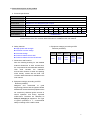
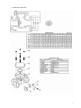
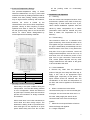
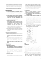
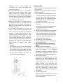
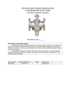
Document No. : MD-QO-04-117 Date : 2009/09/10 Version : 1.0 SF-PN16 Flanged Check Valves, Swing Type, API 603 PN 16 USER MANUAL Modentic Industrial Corporation 14F-1,No.57Taya Rd.,Taichung,Taiwan,R.O.C. Email:[email protected] http://www.modentic.com.tw WARRANTY Modentic warrants its products against defects in manufacturing if the products Are used for the purposes for which they are manufactured and sold. This warranty Shall expire one year from date of shipments. 1. To use for company in Europe who will place the product on the market , please amend which necessary. 2.Modentic reserves the right to change any details without prior notice. Contents 1. General Precautions 2. General Description of Product 3. Pressure-Temperature Ratings 4. Delivery Condition and Storage 5. Installation and Operation 6. Put into service 7. Dangers of inappropriate use 8. Maintenance 9. Corrosion Data 10. Use in potential explosive atmosphere areas 11. Marking Importer, Agent or Distributor responsible for servicing 1. General Precautions a. Operation: leakage. High fluid velocity or the presence of solid particles in suspension will further reduce seat life in throttling applications. The Check Valves are used to check and control liquid media, e.g. sewage and wastewater, where the media has solid matter volume of more than 5%, a free flow is required for operational safety reason. Valve in which the obturator movement is f. Do not disassembly when bearing pressure. Valve is not equipped with pressure access device. User should check it by other method through its piping system. g. Do not touch the surface of valve at high temperature condition. linear and, in the seating area, at right angle to the direction of flow. b. Material Selection: The possibility of material deterioration in service and the need for periodic inspections is depended on the contained fluid. Carbide phase conversions to graphite, oxidation of ferrite materials will decrease in ductility of carbon steels at low temperature are among those items. However information about corrosion data is provided together with this user manual, the user is requested to take attention or consideration to determine the suitability of material in their application. h. Not allowed for unstable fluid, otherwise specified with PED catogory III in Declaration of conformity or/and in this user manual. i. Use in potential explosive atmosphere safely, see section 10 for detail. c. Pressure-Temperature rating: The Pressure-Temperature rating is considered for static pressure. Please refer to P & T rating section 3 for actual application. The allowable temperature is between -20°C and 180°C. Do not exceed the temperature range to avoid danger. d. Liquids with high fluid velocity: When valves must be operated frequently on liquids with very high velocity, a check shall be made with the valve distributor or manufacturer for appropriate advice to minimize the possibility of seat deformation, especially when they are highly pressurized on high-temperature line. e. Throttling service: Valves are generally not recommended for throttling service, where both the fluid flow and the leading edge of the ball can damage or deform the resilient ball seats causing 1 2. General description of the product a. Technical specification Model: CHECK VALVES Port: Standrad Port End connection: Flanged End Service fluid Dangerous or non-dangerous gas or liquid Service temp. -20°C to 180°C Nominal Size NPS 1/2’’ Nominal Size DN Nominal pressure PN 3/4’’ 1” 1½” 2” 2½” 3” 4’’ 5’’ 6’’ 8’’ 10’’ 12’’ 15 20 25 40 50 65 80 100 125 150 200 250 300 PN16 PN16 PN16 PN16 PN16 PN16 PN16 PN16 PN16 PN16 PN16 PN16 PN16 Shell Material 1.4408/EN1503-1 Note 1: User shall consider the material’s anti-corrosion feature of components which directly contact with the fluid. The corrosion data information is available in this user manual. b. Safety features Appropriate shell strength Anti-blow out stem design Anti-static design Pressure release hole at ball Pressure release channel at ball seat c. Dimensions and Parts list See the following drawing for the detailed external dimensions of each nominal size, the components list and materials available. User shall consider the material’s anti-corrosion feature of seals and packing which directly contact with the fluid. The corrosion data information is available in this user manual. e. Equipment category according to PED Directive (97/23/EC) Nominal Pressure PN16 S.E.P Category I CategoryII CategoryIII DN15 DN20 DN25 DN65 DN80 DN100 DN125 DN150 DN200 DN40 DN50 DN250 DN300 d. Equipment category according to ATEX Directive (94/9/EC) Designed and constructed to good engineering practice and the ignition hazard assessment ensure that the equipment does not contain any effective ignition sources in normal operation and during expected malfunctions. Therefore we classified as Group II, Category 2 equipment. The Type of ignition protection is ‘c’, constructional safety according to EN 13463-5:2003. 2 f. Dimensions/ Parts List 3 3. Pressure-Temperature Ratings The pressure-temperature rating of Check Valves are determined, not only by valve shell materials, but also by sealing materials used for Gasket, and stem packing. Sealing materials may be high molecule, elasticity and hardness, however, the choice is limited by the characteristics of the service fluid, temperature, pressure, velocity of fluid, frequency of valves operation and sizes of valves etc, Followings are the general rating chart for non-shock fluid service for Check Valves distinguished by nominal pressure and sealing materials. off the packing under an unnecessary situation. 5. Installation and Operation 5.1 Cleaning Even the valves was transported under a clean environment, operator must check is there any foreign body or dusts inside the bore. If yes, clean it before installation. Operator clean the valves by water, compression air, or steam (automation valve shall be cleaned only with water or steam, the compression air is not allowed.) 5.2 Thread cutting Care should be taken not to thread-cut the pipes excessively. Care should be taken not to over-tighten the pipe connected to the valve. If the pipe is inadvertently screwed deep into the thread chamber of the valve, it may deform the body disc. Prior to pipe connection, remove all foreign material deposits, such as mud, rust, oil and swarf, from the thread-cut portion of the pipe. Prior to pipe connection, remove sand, mud, molten spatter deposits and any other foreign materials from the interior of the pipes to be connected to the valve 5.3 Valve Installation Temp. (°C) -20 to 0 0 to 50 50 to 100 100 to 150 150 to 200 PN16 Bar 14.7 14.3 12.0 11.2 10.3 4. Delivery Condition and Storage Valves stay in the open condition during the transportation, such that the seating material is not in compression. Valves are drained of any test liquid. The body ends are covered to prevent the introduction of foreign materials and moisture. a. Remove any swarf from the thread-cut portion of the pipe, then wrap with Teflon tap, or apply a thin coat of an appropriate liquid sealant (pipe compound), to that portion. The liquid sealant should be selected with due consideration to the kind and temperature of the fluid, and must be applied on the thread of the pipe. b. When a screwed-end valve will be connected to the pipe, be sure to hold the pipe in the pipe vice and screw the valve onto it. In this case, always apply the wrench to the connected end of the valve Connecting to Valves must store in an indoor warehouse to avoid dusts and other foreign object. The elastomeric seating shall be protected from ultra violet light. Do not exposed in an open space without body end cover. Do not take pipeline c. Select the correct specification of bolts to fasten the flange with pipeline. 5.4 Hanger Inspection 4 Proper installation and maintenance of the pipe hangers are essential for the proper functioning of the valve installed. The valve and adjoining pipes should always be kept in a straight line. 6. Put into service a. Once pipe installation is completed, open all valves completely and flush the piping with air, water or steam. b. After flushing, close the valves completely and check that they function properly, if the valves do not close, disassembly and inspection should be performed. c. Systems hydrostatic test Before delivery, valves are tested 1.5 times the allowable working pressure at ambient temperature in open position. After installation, the pipe line system may subject to system tests, as condition not to exceed the maximum working pressure. flange, tight the bolts of the flange end caps, the force must distribute on the every single bolt evenly. The order to tight the bolts need to be symmetrically. For long-term purpose, it is need to be re-installed with new seal. c. Disassembly (NOTE If complete disassembly is necessary, replacement of all seats and seals is recommended.) (1) To dismantle the valve must follow the procedure below. (2) It doesn’t matter where the position of valve located is; usually it contained the seal up fluid, so operator must be very carefully when moving the valve on the pipe. It must open the ball a little and let the fluid come out slowly, it also need to watch out the poisonous and inflammability objects if there is any. (3) To lift the screenl by hoist, it must make the protection on corner to avoid the screendamaged by metal contacted. d. After pressure testing, user shall operate the valve again about 3 times to ensure the function. 7. Dangers of inappropriate use a. Never uses the product exceed its allowed condition, such as pressure, temperature and fluid. b. If the product has any inappropriate use, the product was damage however there are no signals occurs immediately. User shall change the product to avoid danger in the future. 8. Maintenance a. Maintenance frequency The maintenance frequency is determined upon the application. User shall consider the time interval depend on the kinds of fluid, flow velocity, operation frequency, high-pressure effect and high-temperature effect etc. b. Emergency repair When leakage occurs at the pipe connection d. Parts inspection, maintenance, and replacement: (1)Check the surface of screen if it is scraped use the PT for inspection if necessary. If there is any damage on the surface, then find out the root cause such as the dirt fluid…etc. avoid the damage factors as far as possible as we can . (2)The damage of the screen surface, to gauge if it is locate on the contacting area of ball and ball seat. If it is the case, then the ball must take a fine milling. If it cause a heavy 5 damaged, then it must welded and re-machined. If it cannot be repaired then change a new screen. (3)If the scraped area is not at the location described in the item (2)above, then it must re-fine milling the damage area again. Otherwise, the screen ball will damage the soft seat during the open and close operation or it will dig out the ball seat and cause a heavy damage to ball and seat. (4)Check the thickness of valve body and cap. As defined in section 1. the body and cap material may wear be cause of the status of fluid.User should decide the frequency for checking thickness. (5) To do the final inspection for a valve, 10 times of open and close operating must be done to ensure all the parts are assembled correctly. To ensure the torque is in a same value during the open/close operation. If the torque is not the same in operation, then there may has some parts in an correct position or interference.please dismantle and re-assembly. Otherwise, the valve will get damaged easily when working on pipeline under higher pressure . e. Assembly For assembly process, it takes the opposite way of dismantle process. The must in the close position during assembling the body and end cap, the stopper must be located at the right place; otherwise, the open and close operation will be opposite. 9. Corrosion Data CF8M,1.4408,SS316 Stainless steel is suitable for the general Application of corrosion , but below conditions shall be concerned: a. HCL in humid or high temperature is more corrosive, wet HCL is more corrosive than dry HCL under 700ºF, while the corrosive, wet HCL and dry HCL are almost the same above 700ºF. the max. tolerance for dry HCL and HCI is 320ºC b. Hydrofluoric acid corrosion easy cause corrosion. c. Phosphoric acid under 65ºCis applicable in any thickness. And so is the boiling Phosphoric acid in 40% d. H2SO4 in normal temperature the thickness under 20% or above 85% are applicable, but the thickness between 20% and 85% are not. Under 50ºCthe thickness must be under 10%, when reach boiling point the thickness should be under 1%. e. HCI under 2% in low temperature. f. Used in seawater minimum content should be more than 2.75% 10. Use in potential explosive atmosphere areas a. Maximum surface temperature It is depends on the heated fluid inside the valve. The limitation of the application temperature is marked on the label. There is no additional temperature raise cause by normal operation and expected malfunction. b. Electro static charges The only non-conductive part of the equipment is the plastic handle grip. The surface resistance of the material does not exceed 1GΩ at (23 2) C and (50 5)% relative humidity. The equipment also designed and constructed with an electrical continuity design between ball, stem and body. Any occurrence of efficient electro static charge will be earthed through the pipe line earthing. c. Containing light metals Materials used in the construction of external parts do not contain light metals more than 7.5% of magnesium. 6 d. Equipment was tested in factory according to high pressure leakage test before delivery. It will not release flammable gases to explosive atmosphere outside the equipment. e. The internal parts, such as seals and packing can be adversely affected by some solvents. List of solvents which are known to be compatible with the seal and packing material are provided in the corrosion data information. f. The equipment also conforms to Pressure Equipment Directive (97/23/EC), The mechanical strength of the structure can withstand the hazard cause by internal pressure. 11. Marking Mfg logo: MD Mfg location: TAICHUNG, Taiwan Mfg year: 2009 CE mark: CE for DN 25 and smaller CE 0035 for DN 32 and larger Max. working pressure: For PN 16: 14.7bar at -20°C, 10.3bar at 180°C ATEX mark II2DGc: Group II, category 2 equipment, Dust & Gas application, Constructional safety according to EN 13463-5:2003. T.F ref. No. ATEX-TF-0701: Technical file reference number provided by ATEX certification body. Other identification such as DN (size in mm), Shell Material (1.4408 or 1.4308 or 1.0619), PN (bar), Heat number are marked on the shell respectively. 7