1
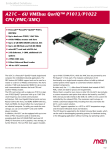
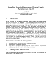
ADC-EMC
User Manual
AD001174
Version 1.3
ADC-EMC User Manual
Copyright © 2007 Alpha Data Parallel Systems Ltd. All rights reserved.
This publication is protected by Copyright Law, with all rights reserved. No part of
this publication may be reproduced, in any shape or form, without prior written
consent from Alpha Data Parallel Systems Limited.
Alpha Data Parallel Systems Ltd.
4 West Silvermills Lane
Edinburgh EH3 5BD
Scotland
UK
Phone: +44 (0) 131 558 2600
Fax:
+44 (0) 131 558 2700
Email: [email protected]
ADC-EMC User Manual
Reserved rights
This manual is designed to provide outline information only. Alpha Data has a
continual policy of improving its products; hence it reserves the right to change
product specification without prior warning. Alpha Data cannot accept any liability
for loss or damages arising from the use of this manual or the use of products
detailed within it.
Trademark acknowledgements
PCI TM, PCI-X TM, PCI EXPRESS® and PCIe® are registered trademarks of PCISIGTM.
Warranty and Support
All Alpha Data products enjoy parts and labour warranty for 12 months after
purchase. The warranty is based on the customer returning the defective goods to
Alpha Data for repair or replacement, which will be at the discretion of the
company. The warranty does not cover damages caused by negligence, misuse, and
normal wear and tear. No liability is accepted by the company for any damage
caused by the use of its hardware or software.
All goods from Alpha Data carry a 6 months free support service. This service is
available by letter, phone, fax, and email. Technical support contracts for longer
periods are available on request. Support contracts for software components also
normally cover the cost of upgrades.
ADC-EMC User Manual
Table of Contents
1.
Introduction ........................................................................................................................... 1-1
1.1
About the Hardware ...................................................................................................... 1-1
1.2
Board Architecture Description ..................................................................................... 1-1
1.3
Board Clocking ............................................................................................................. 1-2
1.4
JTAG Debugging .......................................................................................................... 1-3
2.
Installation ............................................................................................................................. 2-4
2.1
Into a PC....................................................................................................................... 2-4
2.2
Adding PMC/XMC cards.............................................................................................. 2-4
2.3
Software Support........................................................................................................... 2-4
2.4
Power Considerations.................................................................................................... 2-5
3.
Hardware Information ............................................................................................................ 3-6
3.1
Switches........................................................................................................................ 3-6
3.2
JP1 ................................................................................................................................ 3-6
3.3
JP4 ................................................................................................................................ 3-6
3.4
J1 JTAG Connector....................................................................................................... 3-6
3.5
J2 / J3 Samtec QSE-DP Connector ................................................................................ 3-7
3.6
J4 Disk Power Connector .............................................................................................. 3-7
3.7
J16 / J17 JTAG Headers ................................................................................................ 3-7
3.8
J18 I2C Header ............................................................................................................. 3-7
3.9
Board LEDs .................................................................................................................. 3-7
3.10
J5 Header Configuration................................................................................................ 3-8
3.11
P15 / P25 XMC Primary Connector............................................................................. 3-10
3.12
P11, P21, P12, P22 PMC Connectors .......................................................................... 3-10
3.13
P13, P23, P14, P24 PMC Connectors .......................................................................... 3-11
Revision History............................................................................................................................ 3-12
ADC-EMC User Manual
1. Introduction
1.1
About the Hardware
The ADC-EMC is a full length PCI Express card designed to carry two PCI Mezzanine Cards
(PMC) or Switched Mezzanine Cards (XMC). It can be used in x1, x2, x4 and x8 PCIe
signalling environments installed in x8 or x16 PCIe slots. There are two PMC slots on the card
which support 32 or 64-bit operation on independent PCI/PCI-X busses. The secondary bus
VIO is configured for 3.3V operation, and a key pin prevents 5V signalling devices from being
installed.
The board has many configurations for XMC support. The high speed serial lanes of two
XMC cards can be connected for inter-XMC communication, can route to the PCI express
bridge for host communication and can route to a Samtec QS-DP connector for intra-carrier
card communication.
The ADC-EMC carrier card also supports features of Alpha Data FPGA boards in a PCI
environment with the provision of Pn4 routing between the two PMC sites and selectively to a
64-way header.
The secondary bus interfaces are rated at up to 133MHz operation in PCI-X mode. The
primary PCIe interfaces are rated for Gen1 at 2.5GHz.
1.2
Board Architecture Description
The ADC-EMC is based on the PEX8525 PCIe switch and PEX8114 PCIe-PCIX bridges.
Each PMC site is connected to an independent PCI/PCI-X bus as shown in Figure 1.
Each of the two PMC sites supports Pn4 IO with quick-switch isolation to permit various IO
combinations. A set of switches on the board enables each of the quick-switch blocks. The IOBus is 64 bits wide and connects to all 64 signals from the Pn4 connector of each PMC site.
Further, all of the IO-Bus can be routed to the J5 header through a quick-switch block that
provides a level of protection to the IO bus signals by limiting the external signal levels.
x4
PEX
8525
PCIe
Switch
PCIe
x8
X8 PCIe
Primary
PCIe
PCIe
P
C
I
e
P
C
I
e
x4
P
C PEX
I 8114
e
P
C
I
X
133MHz
PMC1
80 pin hdr
x4
J
1
1
J
1
2
J
1
3
J
1
4
J
1
5
64 I/O
mux
64 I/O
X8 serdes
64 I/O
P
C PEX
I 8114
e
P
C
I
X
133MHz
PMC2
J
2
1
J
2
2
J
2
3
J
2
4
J
2
5
x4
Figure 1 ADC-EMC Board Block Diagram
1-1
ADC-EMC User Manual
x4
hdr
hdr
x4
x4
0-3
PCIe
PEX
8525
PCIe
Switch
PCIe
PCIe
P
C
I
e
J15
x4
4-7
PMC1
X4 serdes
P
C
I
e
x4
X4 serdes
PMC2
4-7
J25
0-3
x8
x4
X8 PCIe
Primary
Figure 2 XMC Switching
Figure 2 shows the interface between primary XMC connectors of the two PMC/XMC sites.
There are two groups of x4 SERDES signals between the two sites using switched routing.
Each SERDES lane (x1) consists of a TX and RX pair.
The first group of x4 connects via a multiplexer to a x4 PCIe port of the 8525 switch to allow
host communication to XMC resources. Alternatively, the XMCs may be connected via the
multiplexer to each other for sideband communication.
The second group of x4 connects via a multiplexer to a Samtec QSE-DP connector to allow
linking of multiple ADC-EMC boards. Alternatively, the XMCs may be connected via the
multiplexer to each other for sideband communication. The cable used to connect 2 carrier
cards via the QSE-DP connectors is a Samtec EQDP-014-06.00-TTR-TBL-2.
1.3
Board Clocking
PEX
8525
P C Ie
S w itc h
P C Ie
P C Ie
P C Ie
P
C
I
e
P
C
I
e
P
C PEX
I 8114
e
IC S
9DB
106
100MHz
X 8 P C Ie
P rim a r y
P
C
I
X
P
C PEX
I 8114
e
P
C
I
X
J
1
5
*
*
* = T r i- s ta t e
J
2
5
Figure 3 Clock Distribution
The clock distribution network on the ADC-EMC uses a 1:6 buffer to replicate the 100MHz
reference clock from the edge connector to all PCI Express devices. Each clock driven to an
XMC connector is automatically disabled if the plug-in card is not present.
1-2
ADC-EMC User Manual
JTAG Debugging
The ADC-EMC features a versatile JTAG debugging chain that has selectable routing to the
carrier card devices, and either of the PMC JTAG headers. The main JTAG connector (J1)
connects to a Xilinx Parallel IV or Xilinx Platform Cable USB using the IDC ribbon cable
provided with these devices.
There are 2 JTAG headers (J16 and J17) which allow connections to the PMC/XMC cards’
JTAG chains by using flying leads which are available from Xilinx. The I/O voltage of the
JTAG header signals is controlled by the VCC signal from the PMC, and is supported from
2.5V to 5.0V.
There are 3 switches on the ADC-EMC that control the routing of the JTAG chain. When the
corresponding switch is closed, the devices will automatically be inserted into the JTAG chain
in the following order: SW2-1 will include the PEX8525, and both PEX8114 devices in the
chain, SW2-2 will include the PMC1 header in the chain, and SW2-3 will include the PMC2
header in the chain. When the corresponding switch is open, the JTAG signals will be set in an
idle state and the JTAG chain routed around them.
The PMC JTAG headers have an auto-detect feature that will remove them from the JTAG
chain if the header is not connected.
Note: Routing is also included for JTAG connections to each PMC via the PMC connectors,
and can be enabled with a firmware change from the factory.
PEX8114
J16 Header
SW
PEX8114
PMC1
J17 Header
SW
SWITCHING (CPLD)
PEX8525
J1
JTAG Header
1.4
PMC2
SW
Figure 4 JTAG Routing
1-3
ADC-EMC User Manual
2. Installation
In order to ensure that the board operates correctly first time, please read these instructions
completely before attempting installation. It will also help you to read the whole manual first so
that you know how you want the board to be set up. The installation instructions for your PC
should be followed at all times.
2.1
Into a PC
The ADC-EMC can be installed in any x8 or x16 PCIe host connector.
2.2
Adding PMC/XMC cards
Fit any PMC modules that are required. If only one PMC module is to be fitted, either site can
be used. PMC site #1 is positioned so that an I/O connector on the module aligns with the
aperture in the ADC-EMC's edge panel. The PMC modules should be supplied with mounting
kits, which normally include spacers, nuts, bolts and washers. Figure 1 shows the typical
assembly of a PMC to the ADC-EMC. It is recommended that washers be used on both sides of
the ADC-EMC to avoid damage to the PCB.
PMC
ADC-EMC
Figure 5 Assembly of a PMC to the ADC-EMC
2.3
Software Support
The ADC-EMC uses transparent bridge devices that are compatible with most operating
systems that adhere to the PCI Bios specification.
No software is required to enable operation of the ADC-EMC.
Configuration of the 8525 switch is by a dedicated pre-programmed SPI EEPROM on the
ADC-EMC. Configuration of each of the 8114 bridges is also by individual dedicated preprogrammed SPI EEPROMs. The 8525 switch can also be controlled via a dedicated I2C
connection available via a header for debug purposes.
2-4
ADC-EMC User Manual
2.4
Power Considerations
The ADC-EMC is designed to support standard PMC or PMC/XMC format boards. These
cards are usually specified to consume a maximum of 7.5W each and these, together with the
background power consumed by the ADC-EMC amount to around 22W, within the budget of a
typical PCI Express slot (x16/x8).
The ADC-EMC can operate using the power provided by the PCI Express edge connector if the
PMC/XMC cards will require less than 19W total. Where additional power is required, a disk
drive type connector is provided to allow a controlled connection to the system power supply to
source and additional 24W (12V at up to 2.0A).
A protection mechanism will prevent the board from exceeding the current limit of the PCIe
connector by more than 50%. A red LED will illuminate and the 12V power will be removed
automatically if this condition is reached. This indicates the auxiliary disk power connector
must also be used. This protection mechanism is set at a higher limit than the recommended
maximum, so care should be taken to ensure the board has adequate power supplied. The
ADC-EMC seamlessly controls the two sources of 12V power, and will not allow current to
flow from one source back to the other (when jumper JP4 is removed).
The PMC/XMC cards are supplied with +12V, -12V, +5V and +3.3V power rails. Figure 6
shows the maximum power limit on each supply rail to the combined load of both PMC/XMC
cards. The system must not exceed any of these limits in the given configuration. The total
power provided to the PMC/XMC cards must not exceed 19W, or 43W if the disk power
connector is supplied.
Using External Power
Connector
43W
43W
18W
28W
25W
PMC Power Limits
Total available for both PMC Sites
+12V Rail available power
-12V Rail available power
+5V Rail available power
+3.3V Rail available power
PCIe Power Only
19W
19W
18W
19W
19W
Figure 6 Power Supply Limits
Disk power
+12V
+12V
+12Ve
Pwr
Mux
psu
+3V3
+5V
pmc1
pmc2
-12V
+3V3
psu
+
seq
1.0V
1.5V
3.3V
pex
switch
+
bridges
X8 PCIe
Primary
Figure 7 Power Supply Diagram
2-5
ADC-EMC User Manual
3. Hardware Information
3.1
Switches
There are 16 switches on the board that are used for configuration settings.
SWITCH
FUNCTION
CLOSED (ON)
OPEN (OFF)
SW1-1
SW1-2
XMC1 NVM WRITE PROHIBIT
ALLOW NON-VOLITILE MEM WRITES
PROHIBIT
XMC2 NVM WRITE PROHIBIT
ALLOW NON-VOLITILE MEM WRITES
PROHIBIT
SW1-3
XMC MUX SELECT LANES 0-1 *
CONNECT LANES TO BRIDGE
CONNECT LANES (J15-J25)
SW1-4
XMC MUX SELECT LANES 2-3 *
CONNECT LANES TO BRIDGE
CONNECT LANES (J15-J25)
SW1-5
XMC MUX SELECT LANES 4-5 *
CONNECT LANES TO HEADER
CONNECT LANES (J15-J25)
SW1-6
XMC MUX SELECT LANES 6-7 *
CONNECT LANES TO HEADER
CONNECT LANES (J15-J25)
SW1-7
XMC1 ROOT COMPLEX **
ENABLE
DISABLE
SW1-8
XMC2 ROOT COMPLEX **
ENABLE
DISABLE
SW2-1
JTAG CARRIER DEBUG
BYPASS CARRIER (8525 & 8114)
INCLUDE IN JTAG CHAIN
SW2-2
JTAG PMC1 DEBUG
BYPASS PMC1 JTAG HEADER
INCLUDE IN JTAG CHAIN
SW2-3
JTAG PMC2 DEBUG
BYPASS PMC2 JTAG HEADER
INCLUDE IN JTAG CHAIN
SW2-4
80 PIN HEADER J5 ENABLE
CONNECT BUSSED Jn4 SIGNALS
HEADER UNCONNECTED
SW2-5
PMC1 J14 BUS CONNECT
CONNECT LOWER 32 BITS
UNCONNECTED
SW2-6
PMC1 J14 BUS CONNECT
CONNECT UPPER 32 BITS
UNCONNECTED
SW2-7
PMC2 J24 BUS CONNECT
CONNECT LOWER 32 BITS
UNCONNECTED
SW2-8
PMC2 J24 BUS CONNECT
CONNECT UPPER 32 BITS
UNCONNECTED
* Note: Switch controls the corresponding lanes of both XMC sites
** Note: Root signal is used in PCI-express mode to enable a processor XMC root features (bus enumeration). It also
the carrier card to propagate the XMC (Reset) MRSTOn to both XMC sites MRSTIn.
3.2
enables
JP1
JP1 is connected to the PortEN signal of the CPLD. It is used at the factory to configure the
device and should and should only be installed in manufacturing as changes to this device
could cause system failure.
3.3
JP4
JP4 should be left installed, unless the system uses separate power supplies for the PCIe
backplane and J4 Power connector. It is connected to the power controller device and can be
removed to enable the OR’ing feature between the disk power connector and PCIe edge
connector. This feature will protect the ADC-EMC from feeding power from one power supply
back to the other.
3.4
J1 JTAG Connector
NC 14
NC 12
TDI 10
TDO 8
TCK 6
TMS 4
VREF 2
13
11
9
7
5
3
1
GND
GND
GND
GND
GND
GND
GND
3-6
ADC-EMC User Manual
For use with Xilinx Parallel IV or Platform Cable USB IDC ribbon cables. For more
information see DS300 or DS097 available at www.xilinx.com.
3.5
J2 / J3 Samtec QSE-DP Connector
(Note: J2 Connects to XMC1 J15 signals, J3 connects to XMC2 J25 signals)
PIN DESCRIPTION
LINK
LINK
DESCRIPTION
PIN
XMC_ DP4 +
1
2
XMC_ DP14 +
TXA
RXA
XMC_ DP4 3
4
XMC_ DP14 –
XMC_ DP5 +
5
6
XMC_ DP15 +
TXB
RXB
XMC_ DP5 7
8
XMC_ DP15 –
XMC_ DP6 +
9
10
XMC_ DP16 +
TXC
RXC
XMC_ DP6 11
12
XMC_ DP16 –
XMC_ DP7 +
13
14
XMC_ DP17 +
TXD
RXD
XMC_ DP7 15
16
XMC_ DP17 –
Unused
17
18
Unused
Unused
19
20
Unused
Unused
21
22
Unused
Unused
23
24
Unused
Unused
25
26
Unused
Unused
27
28
Unused
3.6
J4 Disk Power Connector
4 3 2 1
+12V
GND
J16 / J17 JTAG Headers
Pin
1
2
3
4
5
6
7
8
9
3.8
GND
NC
3.7
Function
VCC (JTAG I/O Voltage input from PMC)
GND
Unused
TCK
NC
TDO
TDI
*KEY* Not Installed
TMS
J18 I2C Header
Pin
1
2
3
4
5
Function
SDA
GND
GPO (General Purpose Output of PEX8525)
VCC (3.3V Fused)
SCL
The 1/10 inch header can be used to access the internal registers of the PEX8525, at I2C bus
address 0x58. The I2C bus is also routed to the XMC connectors J15 and J16 with I2C channel
select addresses of 0x00 and 0x01 respectively. The ADC-EMC board has the necessary pullups for I2C communication.
3.9
Board LEDs
Reference
Color
Function
D1
Green
PCIe-PCI Bridge PMC2 Port Good
D2
Green
PCIe-PCI Bridge PMC1 Port Good
D3
Green
PCIe Host Port Good
3-7
ADC-EMC User Manual
D4
Green
3V3 Power OK Indicator
D5
Green
XMC2 PCIe Port Good
D6
Green
XMC1 PCIe Port Good
D7
Green
12V Power OK Indicator
D8
Red
PCIe 12V Supply Limit Exceeded
3.10 J5 Header Configuration
The IO header, J5, is suitable for mating with IDC connectors and is a RN P50E-080-P1-SR1TG or equivalent. The signaling level is dependant on the PMC drivers and the header inputs,
but is limited to 3.3V in either direction by level shifting circuitry on the ADC-EMC carrier
card.
2
80
1
79
J5
gnd
gnd
gnd
gnd
gnd
Pn4-1
Pn4-2
Pn4-5
Pn4-6
Pn4-9
Pn4-10
Pn4-13
Pn4-14
Pn4-17
Pn4-18
Pn4-21
Pn4-22
Pn4-25
Pn4-26
Pn4-29
Pn4-30
Pn4-33
Pn4-34
Pn4-37
Pn4-38
Pn4-41
Pn4-42
Pn4-45
Pn4-46
Pn4-49
Pn4-50
Pn4-53
Pn4-54
Pn4-57
Pn4-58
Pn4-61
Pn4-62
gnd
gnd
gnd
1
3
5
7
9
11
13
15
17
19
21
23
25
27
29
31
33
35
37
39
41
43
45
47
49
51
53
55
57
59
61
63
65
67
69
71
73
75
77
79
2
4
6
8
10
12
14
16
18
20
22
24
26
28
30
32
34
36
38
40
42
44
46
48
50
52
54
56
58
60
62
64
66
68
70
72
74
76
78
80
gnd
gnd
gnd
gnd
gnd
Pn4-3
Pn4-4
Pn4-7
Pn4-8
Pn4-11
Pn4-12
Pn4-15
Pn4-16
Pn4-19
Pn4-20
Pn4-23
Pn4-24
Pn4-27
Pn4-28
Pn4-31
Pn4-32
Pn4-35
Pn4-36
Pn4-39
Pn4-40
Pn4-43
Pn4-44
Pn4-47
Pn4-48
Pn4-51
Pn4-52
Pn4-55
Pn4-56
Pn4-59
Pn4-60
Pn4-63
Pn4-64
gnd
gnd
gnd
The IO header is optimised for LVDS pairing to ADM-XRC-4FX and later mezzanine card
connections. All odd number J5 header signals are “P” with even numbers being “N”. For
example J5-11 and J5-12 are a P/N pair connected to Pn4-1 and Pn4-3. The pairing on this
connector is consistent with the heritage ADC-PMC board, and the routing from Pn4 is
updated for the new pairing system on the ADM-XRC-4FX and later PMC boards.
3-8
ADC-EMC User Manual
3-9
ADC-EMC User Manual
3.11 P15 / P25 XMC Primary Connector
01
02
03
04
05
06
07
08
09
10
11
12
13
14
15
16
17
18
19
A
B
C
D
E
F
DP00+
DP003.3V
DP01+
DP01VPWR
GND
GND
NC
GND
GND
MRSTI#
DP02+
DP023.3V
DP03+
DP03VPWR
GND
GND
NC
GND
GND
MRSTO#
DP04+
DP043.3V
DP05+
DP05VPWR
GND
GND
NC
GND
GND
+12V
DP06+
DP063.3V
DP07+
DP07VPWR
GND
GND
NC
GND
GND
-12V
NC
NC
NC
NC
NC
VPWR
GND
GND
NC
GND
GND
GA0
DP10+
DP10NC
DP11+
DP11VPWR
GND
GND
GA1
GND
GND
MPRESENT#
DP12+
DP12NC
DP13+
DP13VPWR
GND
GND
GA2
GND
GND
MSDA
DP14+
DP14NC
DP15+
DP15VPWR
GND
GND
MVMRO
GND
GND
MSCL
DP16+
DP16NC
DP17+
DP17NC
GND
GND
NC
GND
GND
NC
REFCLK +
REFCLKNC
PCIE_WAKE
PCIE_ROOT
NC
Notes:
VPWR = 5.0V
JTAG Connections pulled high to inactive state and TDI is connected to TDO.
For signal definitions, see VITA42.0, VITA42.2 (Serial Rapid IO) or VITA42.3 (PCI-Express)
3.12 P11, P21, P12, P22 PMC Connectors
Pn1/Jn1 32 Bit PCI
Pin Signal
Signal
Pin
1
TCK
-12V 2
3
Ground
INTA# 4
5
INTB#
INTC# 6
7
BUSMODE1#
+5V 8
9
INTD#
NC 10
11
Ground
NC 12
13
CLK
Ground 14
15
Ground
GNT# 16
17
REQ#
+5V 18
19
V(I/O)
AD[31] 20
21
AD[28]
AD[27] 22
23
AD[25]
Ground 24
25
Ground
C/BE[3]# 26
27
AD[22]
AD[21] 28
29
AD[19]
+5V 30
31
V(I/O)
AD[17] 32
33
FRAME#
Ground 34
35
Ground
IRDY# 36
37
DEVSEL#
+5V 38
39
PCIXCAP
LOCK# 40
41
NC
NC 42
43
PAR
Ground 44
45
V(I/O)
AD[15] 46
47
AD[12]
AD[11] 48
49
AD[09]
+5V 50
51
Ground
C/BE[0]# 52
53
AD[06]
AD[05] 54
55
AD[04]
Ground 56
57
(I/O)
AD[03] 58
59
AD[02]
AD[01] 60
61
AD[00]
+5V 62
63
Ground
REQ64# 64
Notes:
V(I/O) = 3.3V
For signal definitions, see IEEE Std 1386-2001
Pin
1
3
5
7
9
11
13
15
17
19
21
23
25
27
29
31
33
35
37
39
41
43
45
47
49
51
53
55
57
59
61
63
Pn2/Jn2 32 Bit PCI
Signal
Signal
+12V
TRST#
TMS
TDO
TDI
Ground
Ground
NC
NC
NC
BUSMODE2#
+3.3V
RST#
BUSMODE3#
3.3V
BUSMODE4#
PME#
Ground
AD[30]
AD[29]
Ground
AD[26]
AD[24]
+3.3V
IDSEL
AD[23]
+3.3V
AD[20]
AD[18]
Ground
AD[16]
C/BE[2]#
Ground
IDSELB
TRDY#
+3.3V
Ground
STOP#
PERR#
Ground
+3.3V
SERR#
C/BE[1]#
Ground
AD[14]
AD[13]
M66EN
AD[10]
AD[08]
+3.3V
AD[07]
REQB#
+3.3V
GNTB#
NC
Ground
NC
NC
Ground
NC
ACK64#
+3.3V
Ground
MONARCH#
Pin
2
4
6
8
10
12
14
16
18
20
22
24
26
28
30
32
34
36
38
40
42
44
46
48
50
52
54
56
58
60
62
64
3-10
ADC-EMC User Manual
3.13 P13, P23, P14, P24 PMC Connectors
Pn3/Jn3 64 Bit PCI
Pin
Signal
Signal Pin
1
NC
Ground 2
3
Ground
C/BE[7]# 4
5
C/BE[6]#
C/BE[5]# 6
7
C/BE[4]#
Ground 8
9
V(I/O)
PAR64 10
11
AD[63]
AD[62] 12
13
AD[61]
Ground 14
15
Ground
AD[60] 16
17
AD[59]
AD[58] 18
19
AD[57]
Ground 20
21
V(I/O)
AD[56] 22
23
AD[55]
AD[54] 24
25
AD[53]
Ground 26
27
Ground
AD[52] 28
29
AD[51]
AD[50] 30
31
AD[49]
Ground 32
33
Ground
AD[48] 34
35
AD[47]
AD[46] 36
37
AD[45]
Ground 38
39
V(I/O)
AD[44] 40
41
AD[43]
AD[42] 42
43
AD[41]
Ground 44
45
Ground
AD[40] 46
47
AD[39]
AD[38] 48
49
AD[37]
Ground 50
51
Ground
AD[36] 52
53
AD[35]
AD[34] 54
55
AD[33]
Ground 56
57
V(I/O)
AD[32] 58
59
NC
NC 60
61
NC
Ground 62
63
Ground
NC 64
Notes:
V(I/O) = 3.3V
For signal definitions, see IEEE Std 1386-2001
Pin
1
3
5
7
9
11
13
15
17
19
21
23
25
27
29
31
33
35
37
39
41
43
45
47
49
51
53
55
58
59
61
63
Pn4/Jn4 User Defined I/O
Signal
Signal
I/O
I/O
I/O
I/O
I/O
I/O
I/O
I/O
I/O
I/O
I/O
I/O
I/O
I/O
I/O
I/O
I/O
I/O
I/O
I/O
I/O
I/O
I/O
I/O
I/O
I/O
I/O
I/O
I/O
I/O
I/O
I/O
I/O
I/O
I/O
I/O
I/O
I/O
I/O
I/O
I/O
I/O
I/O
I/O
I/O
I/O
I/O
I/O
I/O
I/O
I/O
I/O
I/O
I/O
I/O
I/O
I/O
I/O
I/O
I/O
I/O
I/O
I/O
I/O
Pin
2
4
6
8
10
12
14
16
18
20
22
24
26
28
30
32
34
36
38
40
42
44
46
48
50
52
54
56
58
60
62
64
3-11
ADC-EMC User Manual
Revision History
Date
Nov-2007
Jun – 2008
Aug – 2008
Rev
1.0
1.1
1.2
Comment
Initial release
Added JP4 Information
Section 3.3
Recommendation to install JP4 unless different power
supplies are used in the system.
Section 3.10
Updated J5 Header table to clarify connections to Pn4 and
pairing of differential signals.
Jun – 2009
1.3
Fixed LED Definitions
3-12


![[Insert the picture here]](http://vs1.manualzilla.com/store/data/005750886_1-61b7896b0a61bec1f004b64a994fc9d3-150x150.png)