1
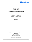
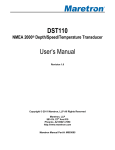
FFM100 Fuel Flow Monitor User’s Manual Revision 1.3 Copyright © 2013 Maretron, LLP All Rights Reserved Maretron, LLP 9014 N. 23rd Ave #10 Phoenix, AZ 85021 http://www.maretron.com Maretron Manual Part #: M003010 Revision 1.3 Page i FFM100 User’s Manual Revision History Revision Description 1.0 Release for Review 1.1 Public Release 1.2 Corrected formatting problems in certain figures Added notes about tamper-proof silicone seals on sensor screws Added information about location of sensors 1.3 Added information about configuration tools Modified troubleshooting guide Added Maretron Proprietary PGN’s for fluid types other than fuel and extended range on trip volume Page ii Revision 1.3 Table of Contents 1 2 3 General ................................................................................................................................1 1.1 Introduction ....................................................................................................................1 1.2 Firmware Revision .........................................................................................................1 1.3 Features ........................................................................................................................1 1.4 FFM100 Accessories .....................................................................................................1 1.5 Quick Install ...................................................................................................................1 1.6 Theory of Operation .......................................................................................................2 1.6.1 Operating Modes ................................................................................................2 1.6.2 Sensor Accuracy .................................................................................................2 1.6.3 Diesel Fuel Flow Measurement ...........................................................................4 1.6.4 Temperature Compensation ...............................................................................5 1.6.5 Fuel Flow Sensor Selection ................................................................................6 1.6.6 Accuracy of Diesel Fuel Flow Measurement .......................................................7 1.6.7 Choosing a Fluid Flow Sensor Mounting Location ..............................................8 Installation ............................................................................................................................8 2.1 Unpacking the Box.........................................................................................................8 2.2 Choosing a Mounting Location ......................................................................................8 2.3 Mounting the FFM100 ....................................................................................................9 2.4 Mounting the Fluid Flow Sensor ....................................................................................9 2.5 Connecting the FFM100 ................................................................................................9 2.5.1 Fluid flow sensor Connections ............................................................................9 2.5.2 NMEA 2000® Connection .................................................................................. 10 Configuring the FFM100 .................................................................................................... 11 3.1 Advanced Configuration .............................................................................................. 12 3.1.1 Configuring Device Instance ............................................................................. 12 3.1.2 Configuring Channel #0 Installation Orientation ................................................ 12 3.1.3 Configuring Channel #1 Installation Orientation ................................................ 12 3.1.4 Configuring Channel #0 Allow Negative Flow ................................................... 12 3.1.5 Configuring Channel #1 Allow Negative Flow ................................................... 13 3.1.6 Configuring Differential Mode Allow Negative Flow .......................................... 13 3.1.7 Configuring Installation Description ................................................................... 13 3.1.8 Configuring NMEA 2000 PGN Enable/Disable .................................................. 13 3.1.9 Restoring Factory Default Settings ................................................................... 13 3.2 Configuring the Device Label ....................................................................................... 13 3.3 Configuring the Operating Mode .................................................................................. 13 3.4 Configuring Channel #0 ............................................................................................... 14 3.4.1 Enabling/Disabling Channel #0 ......................................................................... 14 3.4.2 Configuring Channel #0 Engine Instance .......................................................... 14 3.4.3 Configuring Channel #0 Engine Label............................................................... 14 3.4.4 Configuring Channel #0 K-factor ....................................................................... 14 3.4.5 Configuring Channel #0 Data Damping Period ................................................. 14 3.4.6 Resetting the Total Volume Recorded for Channel #0 ...................................... 14 3.4.7 Configuring Channel #0 Temperature Instance ................................................ 14 3.4.8 Configuring Channel #0 Temperature Source ................................................... 15 3.4.9 Configuring Channel #0 Temperature Label ..................................................... 15 Revision 1.3 Page iii FFM100 User’s Manual 4 5 6 7 8 9 3.5 Configuring Channel #1 ............................................................................................... 15 3.5.1 Enabling/Disabling Channel #1 ......................................................................... 15 3.5.2 Configuring Channel #1 Engine Instance .......................................................... 15 3.5.3 Configuring Channel #1 Engine Label............................................................... 15 3.5.4 Configuring Channel #1 K-factor ....................................................................... 15 3.5.5 Configuring Channel #1 Temperature Coefficient ............................................. 15 3.5.6 Configuring Channel #1 Data Damping Period ................................................. 16 3.5.7 Resetting the Total Volume Recorded for Channel #1 ...................................... 16 3.5.8 Configuring Channel #1 Temperature Instance ................................................ 16 3.5.9 Configuring Channel #1 Temperature Source ................................................... 16 3.5.10 Configuring Channel #1 Temperature Label ..................................................... 16 Maintenance....................................................................................................................... 17 Troubleshooting ................................................................................................................. 18 Technical Specifications ..................................................................................................... 19 Technical Support .............................................................................................................. 20 Installation Template .......................................................................................................... 21 Maretron (2 Year) Limited Warranty ................................................................................... 22 Table of Figures Figure 1 - M1RSP-2R-E8 and M2RSP-2R-E8 Accuracy and Pressure Loss............................. 3 Figure 2 - M4ARP-2-E8 Typical Accuracy and Pressure Loss .................................................. 4 Figure 3 - Diesel Fuel Rate Measurement Fluid Flow Sensor Locations ................................... 5 Figure 4 – Fluid Flow Sensor Selection Chart for Diesel Engine Applications ........................... 6 Figure 5 – Mounting the FFM100 .............................................................................................. 9 Figure 6 – Fluid flow sensor Connection Diagram ................................................................... 10 Figure 7 – NMEA 2000® Connector Face Views ..................................................................... 11 Figure 8 – Troubleshooting Guide ........................................................................................... 18 Figure 9 – Mounting Surface Template ................................................................................... 21 Table of Appendices Appendix A – NMEA 2000® Interfacing.................................................................................... A1 Page iv Revision 1.3 1 General 1.1 Introduction Congratulations on your purchase of the Maretron Fuel Flow Monitor (FFM100). Maretron has designed and built your monitor to the highest standards for years of reliable, dependable, and accurate service. Maretron’s Fuel Flow Monitor (FFM100) is used to adapt up to two positive displacement fluid flow sensors to the NMEA 2000® network (Fluid Flow sensors sold separately). This allows you to observe engine fuel usage on a vessel where there are NMEA 2000® compatible displays. With the appropriate sensor, the FFM100 reports flow rate for diesel engines or gasoline engines. The FFM100 can be used with the positive displacement sensors to detect flow rates of many other types of fluid as well, including water, hydraulic oil, or other fluids. The Maretron FFM100 is designed to operate within the harsh demands of the marine environment. However, no piece of marine electronic equipment can function properly unless installed, calibrated, and maintained in the correct manner. Please read carefully and follow these instructions for installation, calibration, and usage of the Maretron FFM100 in order to ensure optimal performance. 1.2 Firmware Revision This manual corresponds to FFM100 firmware revision 1.1.2.1. 1.3 Features The Maretron FFM100 has the following features: NMEA 2000® interface Adapts up to two fluid flow sensors to the NMEA 2000 network Each channel independently programmable to match fluid flow sensor characteristics The FFM100 can be programmed to measure a differential flow rate using two fluid flow sensors (supply and return flow for diesel engines) or two completely independent flow rates. 1.4 FFM100 Accessories Maretron offers the following accessories for the FFM100: M1RSP-2R-E8 Fuel Flow Sensor 20 to 200 HP (0.53 to 26.4 GPH, 2 to 100 LPH) M2RSP-2R-E8 Fuel Flow Sensor 200 to 1000 HP (4 to 132 GPH, 15 To 500 LPH) M4ARP-2-E8 Fuel Flow Sensor 1000 to 3000 HP (48 to 396 GPH, 180 To 1500 LPH) 1.5 Quick Install Installing the Maretron FFM100 involves the following steps. Please refer to the individual sections for additional details. Revision 1.3 Page 1 FFM100 User’s Manual 1. 2. 3. 4. 5. 6. 7. Unpack the Box (Section 2.1) Choose a Mounting Location (Section 2.2) Mount the FFM100 (Section 2.3) Mount the Flow Sensors and Connect Fluid Lines (Section 2.4) Connect the Flow Sensors to the FFM100 (Section 2.5.1) Connect the FFM100 to the NMEA 2000® network (Section 2.5.1) Configure the FFM100 (Section 3) 1.6 Theory of Operation The FFM100 operates by using positive displacement fluid flow sensors. These sensors are volumetric (they measure the volume of fluid passing through them as opposed to the mass of the fluid). 1.6.1 Operating Modes The FFM100 can operate in one of two user-selectable operating modes: 1) Differential Flow Rate – this mode is used for diesel engines that recirculate unused fuel back into the fuel tank. These engines will have separate supply and return fuel lines. In this mode, Channel 0 must be connected to the fuel flow sensor on the supply fuel line, and Channel 1 must be connected to the fuel flow sensor on the return fuel line. 2) Two Independent Flow Rates – the FFM100 can measure flow rates from two independent sources; for example, a water flow rate on one channel and a gasoline fuel flow rate on another channel. 1.6.2 Sensor Accuracy The M1RSP-2R-E8, M2RSP-2R-E8, and M4ARP-2-E8 fuel flow sensors use positive displacement technology. These sensors are extremely accuracy over a wide flow range. Please refer to Figure 1 below for a chart detailing typical accuracy and pressure loss versus flow rate for the M1RSP-2R-E8 and M2RSP-2R-E8 fuel flow sensors. Page 2 Revision 1.3 Figure 1 - M1RSP-2R-E8 and M2RSP-2R-E8 Accuracy and Pressure Loss Please refer to Figure 2 below for a chart detailing typical accuracy and pressure loss versus flow rate for the M4ARP-2-E8 fuel flow sensor. Revision 1.3 Page 3 FFM100 User’s Manual Figure 2 - M4ARP-2-E8 Typical Accuracy and Pressure Loss 1.6.3 Diesel Fuel Flow Measurement Most diesel engines do not use all of the fuel that is supplied to them by the fuel pump via the supply line. A portion of the fuel is consumed by the engine, but the majority of the fuel is used for cooling the injection system and returned to the fuel tank via the return line. For diesel engines, the FFM100 will operate in its differential mode, and will measure the net fuel consumption of these engines by separately measuring the fuel sent to the engine via the supply line and the fuel returned to the fuel tank from the engine via the return line. The difference between these two readings is the fuel consumption of the engine. Please refer to Figure 3 below for a system diagram demonstrating the location of the supply and return fuel flow sensors in a diesel fuel system. Page 4 Revision 1.3 Display/MFD Supply Fuel Flow Sensor Fuel Filter Engine Return Fuel Flow Sensor Fuel Tank Figure 3 - Diesel Fuel Rate Measurement Fluid Flow Sensor Locations 1.6.4 Temperature Compensation The task of computing fuel consumption for a diesel engine is further complicated by the following two factors: 1) Diesel fuel expands when heated 2) Diesel fuel is heated as it passes through the engine When using volumetric sensors such as positive displacement sensors or turbine flow sensors, simply subtracting the return flow rate from the supply flow rate without taking these factors Revision 1.3 Page 5 FFM100 User’s Manual into account will result in the fuel consumption being underestimated. In fact, without compensating for temperature, if the engine were consuming no fuel, the return fuel flow rate is greater than the supply fuel rate, since the fuel is expanded by the engine’s heat as it passes through the injection system. The M1RSP-2R-E8, M2RSP-2R-E8, and M4ARP-2-E8 fuel flow sensors feature embedded temperature sensors, so that the temperature of both the supply and return fuel is sensed and used in real time by the FFM100 to compensate for the expansion of the fuel due to the increase in temperature, for the most accurate possible fuel flow measurement. 1.6.5 Fuel Flow Sensor Selection The fluid flow sensors must likewise be sized to accommodate the flow rate of fluid flowing through the supply and return lines, as opposed to the net fuel consumption used by the engine. If too small a fuel flow sensor is used, excessive back pressure will occur through the sensors and the sensor may wear prematurely. For example, consider the M1RSP-2R-E8 fluid flow sensor, which is rated at a maximum flow rate of 26.4 GPH (100 LPH). A typical diesel engine will consume 20% of the fuel sent to the engine, so under this assumption, this fuel sensor will be able to support a diesel engine which consumes 5.28 GPH (20 LPH). The fluid flow sensor you select must have sufficient range to measure the supply flow rate of the engine whose fuel consumption you are monitoring. The table in Figure 4 below shows the maximum fuel supply flow rates that can be sensed by each fuel flow sensor, and approximate engine power ranges for each fuel flow sensor type. Please consult your engine’s documentation or contact your engine manufacturer for the maximum supply fuel flow rate (sometimes called fuel feed rate) for the specific engine whose fuel consumption you wish to monitor. Fluid Flow Sensor Flow Rate Range M1RSP-2R-E8 0.53 to 26.4 GPH 2 to 100 LPH 4 to 132 GPH 15 to 500 LPH 48 to 396 GPH 180 to 1500 LPH M2RSP-2R-E8 M4ARP-2-E8 Approximate Engine Power Range 20 to 200 HP 14.9 to 149 kW 200 to 1000 HP 149 to 746 kW 1000 to 3000 HP 746 to 2237 kW Figure 4 – Fluid Flow Sensor Selection Chart for Diesel Engine Applications If you are unable to obtain maximum supply fuel flow rates from the engine manufacturer, another way to get a good estimate of the engine’s fuel feed rate is to disconnect the fuel return line from the tank and direct it into a five gallon bucket. Run the engine at maximum RPM until the bucket is filled, and calculate the return fuel flow rate by dividing the amount of fuel in the bucket by the amount of time it took to fill the bucket. For instance, if it took 15 minutes (0.25 hour) to fill the five gallon bucket, the return flow rate is: Page 6 Revision 1.3 Max. return flow rate = 5 gallons / 0.25 hours = 20 gallons per hour Now, add in the engine’s consumption fuel rate at this RPM, which should be readily available from the manufacturer’s documentation for the engine, and calculate the maximum supply flow rate as follows: Max. supply flow rate = Max. return flow rate + Max. consumption flow rate For this example, let’s assume that the engine manufacturer’s documentation shows that the fuel consumption of the engine at the maximum RPM is 5 gallons per hour. We can calculate the maximum supply flow rate as follows: Max. supply flow rate = 20 gallons per hour + 5 gallons per hour = 25 gallons per hour. The 25 gallons per hour maximum supply flow rate is within the specifications of the M1RSP2R-E8 fuel flow sensor, so the M1RSP-2R-E8 is appropriate for this fuel flow application. If the maximum supply flow rate had exceeded the M1RSP-2R-E8 specifications, you would have needed to select the next larger fuel flow sensor, the M2RSP-2R-E8. 1.6.6 Accuracy of Diesel Fuel Flow Measurement Even though the fluid flow sensors used with the FFM100 are rated at ±0.25% accuracy, since the fuel consumption measurement is calculated as the difference of the supply and return fuel flow rates, the accuracy of the fuel consumption measurement when operating in differential mode for a diesel engine depends on the ratio of the flow rate of fuel consumed by the engine to the flow rate of fuel supplied to the engine. Following is a worst-case analysis of diesel engine fuel consumption measurement accuracy with a 4:1 supply rate to consumption rate ratio (this ratio is typical of many diesel engines). This assumes that both the supply and return fuel flow sensors are at the limit of their specifications in the way that will cause the most inaccuracy in the fuel consumption calculation. Actual Supply Flow Rate: Actual Engine Fuel Consumption: Actual Return Flow Rate: Measured Supply Flow Rate: Measured Return Flow Rate: Calculated Fuel Consumption: Error: 80.0 20.0 60.0 80.2 LPH LPH LPH LPH (This assumes that the supply sensor reads 0.25% high) 59.85 LPH (This assumes that the return sensor reads 0.25% low) 20.35 LPH 1.75 % The resulting 1.75% error value is what appears in the FFM100 specifications for differential flow rate accuracy. Revision 1.3 Page 7 FFM100 User’s Manual 1.6.7 Choosing a Fluid Flow Sensor Mounting Location Choosing a proper mounting location for fluid flow sensors is critical to obtaining accurate tank level measurements. Because of the positive displacement design of the FFM100 sensors, no pulse dampening or flow straightening is necessary. The installation instructions packaged with each fuel flow sensor contain details on choosing a mounting location and installation. The ideal location for the supply fuel flow sensor is immediately after the fuel filter. NOTE: Maretron fuel flow sensors have anti-tamper blue silicone on one or more of the screws that hold the body of the sensor together. Do not remove these screws. Removing these screws will void the warranty on the sensor. 2 Installation 2.1 Unpacking the Box When unpacking the box containing the Maretron FFM100, you should find the following items: 1 – FFM100 Fuel Flow Monitor 1 – Parts Bag containing 4 Stainless Steel Mounting Screws 1 – FFM100 User’s Manual 1 – Warranty Registration Card If any of these items are missing or damaged, please contact Maretron. 2.2 Choosing a Mounting Location Please consider the following when choosing a mounting location. 1. The FFM100 is waterproof, so it can be mounted in a damp or dry location. 2. The orientation is not important, so the FFM100 can be mounted on a horizontal deck, vertical bulkhead, or upside down if desired. 3. The FFM100 is temperature-rated to 55°C (130°F), so it should be mounted away from engines or engine rooms where the operating temperature exceeds the specified limit. Page 8 Revision 1.3 2.3 Mounting the FFM100 Attach the FFM100 securely to the vessel using the included stainless steel mounting screws or other fasteners as shown in Figure 5 below. Do not use threadlocking compounds containing methacrylate ester, such as Loctite Red (271), as they will cause stress cracking of the plastic enclosure. Figure 5 – Mounting the FFM100 2.4 Mounting the Fluid Flow Sensor Since the FFM100 supports different fluid flow sensors depending on the application, please consult the installation instructions that are packaged with each sensor for detailed installation instructions. 2.5 Connecting the FFM100 The FFM100 requires two types of electrical connections: 1) the fluid flow sensor connections, which are described in Section 2.5.1, and 2) the NMEA 2000® connection (refer to Section 2.5.2). 2.5.1 Fluid flow sensor Connections The FFM100 fluid flow sensor connections are made by connecting to the 12-pin terminal strip on the top of the unit. First, remove the four screws at the corners of the unit detaching the splash guard from the unit. On the bottom of the splash guard, you will find a label detailing the wire connection to pin number assignments, which are repeated in the table below. Revision 1.3 Page 9 FFM100 User’s Manual Pin # 1 2 3 4 5 6 7 8 9 10 11 12 Signal Name P0 G0 A0 B0 C0 T0 P1 G1 A1 B1 C1 T1 Connection Fluid flow sensor 0 power connection Fluid flow sensor 0 ground connection Fluid flow sensor 0 phase A connection Fluid flow sensor 0 phase B connection Fluid flow sensor 0 phase C connection Fluid flow sensor 0 temperature sensor connection Fluid flow sensor 1 power connection Fluid flow sensor 1 ground connection Fluid flow sensor 1 phase A connection Fluid flow sensor 1 phase B connection Fluid flow sensor 1 phase C connection Fluid flow sensor 1 temperature sensor connection Table 1 - Fluid Flow Sensor Connections For differential mode, Channel 0 must be connected to the fuel flow sensor on the supply fuel line, and Channel 1 must be connected to the fuel flow sensor on the return fuel line. Red Black Orange Blue Green White Please refer to Figure 6 for connecting the FFM100 to a M1RSP-2R-E8, M2RSP-2R-E8, or M4ARP-2-E8 fluid flow sensor. This figure shows the connection of the fluid flow sensor to channel 0. Connections to other channels are similar. Fluid flow sensor FFM100 Screw Terminals 2 3 4 5 6 7 8 9 10 11 12 P0 G0 A0 B0 C0 T0 P1 G1 A1 B1 C1 T1 1 Figure 6 – Fluid flow sensor Connection Diagram 2.5.2 NMEA 2000® Connection The NMEA 2000® connector can be found on the side of the enclosure. The NMEA 2000® connector is a round five pin male connector (see Figure 7). You connect the FFM100 to an NMEA 2000® network using a Maretron NMEA 2000® cable (or an NMEA 2000® compatible cable) by connecting the female end of the cable to the FFM100 (note the key on the male connector and keyway on the female connector). Be sure the cable is connected securely and Page 10 Revision 1.3 that the collar on the cable connector is tightened firmly. Connect the other end of the cable (male) to the NMEA 2000® network in the same manner. The FFM100 is designed such that you can plug or unplug it from an NMEA 2000® network while the power to the network is connected or disconnected. Please follow recommended practices for installing NMEA 2000® network products. Figure 7 – NMEA 2000® Connector Face Views 3 Configuring the FFM100 The FFM100 has several configurable parameters, which are shown below, including the default values. If you are not using the default values, then you will need to configure the FFM100 appropriately. You can configure the FFM100 using a Maretron DSM150 display, DSM250 display, or Maretron N2KAnalyzer software. For full details on the configuration procedure, please refer to the User’s Manual for the product which you are using to configure the FFM100. 1. Advanced Configuration (Section 3.1) a. Device Instance b. Channel-0 Installation c. Channel-1 Installation d. Channel-0 Allow negative flow e. Channel-1 Allow negative flow f. Differential Mode Allow negative flow g. Installation Description h. NMEA 2000 PGN Enable/Disable i. Restore Factory Defaults 2. Device Label (Section 3.2) 3. Operating Mode (Section 3.3) 4. Channel #0 (Section 3.4) a. Channel Enable/Disable (Section 3.4.1) b. Engine Instance (Section 3.4.2) Revision 1.3 Page 11 FFM100 User’s Manual c. Engine Label (Section 3.4.3) d. K-Factor (Section 3.4.4) e. Data Damping Period (Section 3.4.5) f. Reset Total Volume Recorded (Section 3.4.6) g. Temperature Instance (Section 3.4.7) h. Temperature Source (Section 3.4.8) i. Temperature Label (Section 3.4.9) 5. Channel #1 (Section 3.5) a. Channel Enable/Disable (Section 3.5.1) b. Engine Instance (Section 3.5.2) c. Engine Label (Section 3.5.3) d. K-Factor (Section 3.5.4) e. Temperature Coefficient (Section 3.5.5) f. Data Damping Period (Section 3.5.6) g. Reset Total Volume Recorded (Section 3.5.7) h. Temperature Instance (Section 3.5.8) i. Temperature Source (Section 3.5.9) j. Temperature Label (Section 3.5.10) 3.1 Advanced Configuration 3.1.1 Configuring Device Instance NMEA 2000® provides a unique device instance for each flow measuring device on a vessel. This value should be programmed in each FFM100 so that each FFM100 is associated with a unique device instance number. The default instance number is 0, which is used to indicate the first FFM100 that is hooked to the network. Subsequent FFM100s connected to the network would be numbered 1, 2, and so on. 3.1.2 Configuring Channel #0 Installation Orientation If you install the Channel #0 fluid flow sensor with the “FLOW” arrow on the sensors pointing in the same direction as the fuel flow, you will not need to change this parameter from the factory default setting. If you inadvertently install the sensor in the reverse direction, rather than reinstalling the sensor, you may change this parameter from “Normal” to “Reverse”, and the FFM100 will compensate for the reversed installation of the flow sensor. 3.1.3 Configuring Channel #1 Installation Orientation If you install the Channel #1 fluid flow sensor with the “FLOW” arrow on the sensors pointing in the same direction as the fuel flow, you will not need to change this parameter from the factory default setting. If you inadvertently install the sensor in the reverse direction, rather than reinstalling the sensor, you may change this parameter from “Normal” to “Reverse”, and the FFM100 will compensate for the reversed installation of the flow sensor. 3.1.4 Configuring Channel #0 Allow Negative Flow The M1RSP-2R-E8, M2RSP-2R-E8, and M4ARP-2-E8 fuel flow sensors are capable of sensing flow in both directions. When this parameter is in the default state of “Yes”, the FFM100 will report reverse flow on Channel #0 as a negative flow rate. If you do not wish to Page 12 Revision 1.3 see negative flow rates from the Channel #0 sensor, you may change this parameter to “No”. When this parameter is set to “No”, the FFM100 will report a zero flow rate for Channel #0 when reverse flow occurs. 3.1.5 Configuring Channel #1 Allow Negative Flow The M1RSP-2R-E8, M2RSP-2R-E8, and M4ARP-2-E8 fuel flow sensors are capable of sensing flow in both directions. When this parameter is in the default state of “Yes”, the FFM100 will report reverse flow on Channel #1 as a negative flow rate. If you do not wish to see negative flow rates from the Channel #1 sensor, you may change this parameter to “No”. When this parameter is set to “No”, the FFM100 will report a zero flow rate for Channel #1 when reverse flow occurs. 3.1.6 Configuring Differential Mode Allow Negative Flow In differential mode, if no fuel consumption occurring but fuel is flowing through both the supply and return fuel flow sensors, the resulting calculated net fuel consumption can result in a small negative value. When this parameter is set to the default state of “No”, the FFM100 will report this as a zero flow rate value. If you wish to see these small negative values transmitted by the FFM100, change the value of this parameter to “Yes”. 3.1.7 Configuring Installation Description You can configure the two installation description parameters with any text you wish. Examples include date of installation, location, etc. NMEA 2000 diagnostic tools such as Maretron N2KAnalyzer® can display this information. 3.1.8 Configuring NMEA 2000 PGN Enable/Disable The FFM100 is capable of transmitting NMEA 2000® messages (or PGNs) associated with monitored fluid senders. You may individually enable or disable each of these messages. You may also change the rate of transmission of each of these messages if desired. 3.1.9 Restoring Factory Default Settings Selecting this configuration option causes all stored parameters in the FFM100 to be reset to the values they contained when the unit was manufactured. 3.2 Configuring the Device Label Program this parameter with a text string which identifies this device. Maretron display products will display this label text when you are selecting data to display. 3.3 Configuring the Operating Mode The FFM100 can be operated in one of two selectable operating modes: 1. Differential Flow Rate (default) – in this mode, the FFM100 measures fuel consumption of a diesel engine by measuring the flow rate of the fuel sent from the fuel tank to the engine and the flow rate of the fuel returned from the engine to the fuel tank, and computing the difference between these two flow rates, with temperature compensation. This difference is the flow Revision 1.3 Page 13 FFM100 User’s Manual rate of the fuel actually consumed by the engine, and is transmitted as a single parameter over the NMEA 2000 network. In this mode, Channel 0 must be connected to the fuel flow sensor on the supply fuel line, and Channel 1 must be connected to the fuel flow sensor on the return fuel line. 2. Two Individual Flow Rates – in this mode, the FFM100 can measure two independent flow rates of any fluids – diesel, oil, water, etc., and transmit the two flow rate measurements as separate parameters over the NMEA 2000 network. 3.4 Configuring Channel #0 3.4.1 Enabling/Disabling Channel #0 By default, the channel is enabled and will measure the flow rate and transmit it over the NMEA 2000 network. If this parameter is programmed to “Disable”, the channel will be completely disabled and will not measure flow rate nor transmit it over the NMEA 2000 network. 3.4.2 Configuring Channel #0 Engine Instance Program this parameter to match the desired engine instance number of the flow rate and total fuel used for this channel. You can program this parameter to any value between 0 and 252. 3.4.3 Configuring Channel #0 Engine Label Program this parameter with a text string which identifies the particular parameter being monitored by this channel. Maretron display products will display this label text when you are selecting data to display. 3.4.4 Configuring Channel #0 K-factor Program this parameter to match the K-factor that appears on the flow sensor connected to this channel. 3.4.5 Configuring Channel #0 Data Damping Period You can configure a damping parameter to smooth the flow rate readings or make them more responsive. The data damping is configurable between 0.2-25.0 seconds. The default data damping period is 3.0 seconds. 3.4.6 Resetting the Total Volume Recorded for Channel #0 The FFM100 maintains the total volume recorded in EEPROM, so that it is maintained across power cycles. Select this menu entry to reset the total volume recorded to zero. 3.4.7 Configuring Channel #0 Temperature Instance Program this parameter to match the desired instance number of the temperature reading for this channel. You can program this parameter to any value between 0 and 252. The default value for this parameter is 0. Page 14 Revision 1.3 3.4.8 Configuring Channel #0 Temperature Source Program this parameter to match the desired instance number of the temperature reading for this channel. You can program this parameter to any value between 0 and 252. The default value for this parameter is 129 (User Defined). 3.4.9 Configuring Channel #0 Temperature Label Program this parameter with a text string which identifies the particular temperature parameter being monitored by this channel. Maretron display products will display this label text when you are selecting data to display. 3.5 Configuring Channel #1 3.5.1 Enabling/Disabling Channel #1 NOTE: This parameter is available only when the Operating Mode of the FFM100 is set to “Two Independent Flow Rates”. By default, the channel is enabled and will measure the flow rate and transmit it over the NMEA 2000 network. If this parameter is programmed to “Disable”, the channel will be completely disabled and will not measure flow rate nor transmit it over the NMEA 2000 network. 3.5.2 Configuring Channel #1 Engine Instance NOTE: This parameter is available only when the Operating Mode of the FFM100 is set to “Two Independent Flow Rates”. Program this parameter to match the desired engine instance number of the flow rate and total fuel used for this channel. You can program this parameter to any value between 0 and 252. 3.5.3 Configuring Channel #1 Engine Label NOTE: This parameter is available only when the Operating Mode of the FFM100 is set to “Two Independent Flow Rates”. Program this parameter with a text string which identifies the particular parameter being monitored by this channel. Maretron display products will display this label text when you are selecting data to display. 3.5.4 Configuring Channel #1 K-factor Program this parameter to match the K-factor that appears on the flow sensor connected to this channel. 3.5.5 Configuring Channel #1 Temperature Coefficient NOTE: This parameter is available only when the Operating Mode of the FFM100 is set to “Differential Mode”. Revision 1.3 Page 15 FFM100 User’s Manual In a diesel engine, the diesel fuel is used to help cool the fuel injection system. Therefore, the fuel returned from the engine to the tank has a higher temperature than the fuel sent to the engine from the tank. Diesel fuel expands when heated. To calculate the most accurate fuel usage measurement, the FFM100 accounts for this expansion by sensing the temperature at the supply flow sensor and the receive flow sensor, and calculating the effect of the temperature difference on the fuel expansion. In order to do this compensation, this parameter is programmed with the appropriate value for thermal expansion coefficient of the fluid being measured. The default value of this field is (0.083%/°C), which is appropriate for diesel fuel. The configuration tools have predefined values for common fluids: diesel, engine oil, gasoline, and water. You may select one of these values or choose your own. 3.5.6 Configuring Channel #1 Data Damping Period NOTE: This parameter is available only when the Operating Mode of the FFM100 is set to “Two Independent Flow Rates”. You can configure a damping parameter to smooth the flow rate readings or make them more responsive. The data damping is configurable between 0.2-25.0 seconds. The default data damping period is 3.0 seconds. 3.5.7 Resetting the Total Volume Recorded for Channel #1 NOTE: This parameter is available only when the Operating Mode of the FFM100 is set to “Two Independent Flow Rates”. The FFM100 maintains the total volume recorded in EEPROM, so that it is maintained across power cycles. Select this menu entry to reset the total volume recorded to zero. 3.5.8 Configuring Channel #1 Temperature Instance Program this parameter to match the desired instance number of the temperature reading for this channel. You can program this parameter to any value between 0 and 252. The default value for this parameter is 0. 3.5.9 Configuring Channel #1 Temperature Source Program this parameter to match the desired instance number of the temperature reading for this channel. You can program this parameter to any value between 0 and 252. The default value for this parameter is 129 (User Defined). 3.5.10 Configuring Channel #1 Temperature Label Program this parameter with a text string which identifies the particular temperature parameter being monitored by this channel. Maretron display products will display this label text when you are selecting data to display. Page 16 Revision 1.3 4 Maintenance Regular maintenance is not required; however, an occasional inspection will ensure continued proper operation of the Maretron FFM100. Perform the following tasks periodically: Clean the unit with a soft cloth. Do not use chemical cleaners as they may remove paint or markings or may corrode the FFM100 enclosure or seals. Do not use any cleaners containing acetone, as they will deteriorate the plastic enclosure. Ensure that the unit is mounted securely and cannot be moved relative to the mounting surface. If the unit is loose, tighten the screws holding the cable ties. Check the security of the cable connected to the NMEA 2000® interface and tighten if necessary. Check the security of all of the fluid flow sensor connections on the top of the unit and tighten if necessary. Revision 1.3 Page 17 FFM100 User’s Manual 5 Troubleshooting If you notice unexpected operation of the Maretron FFM100, follow the troubleshooting procedures in this section to remedy simple problems. Symptom No Fuel Flow data visible on NMEA 2000® network. 1. 2. 3. 4. No Fluid Temperature data visible on NMEA 2000® network. 1. 2. 3. Fluid will not flow through the fluid flow sensors 1. 2. 3. Reduced flow 1. through the fluid flow sensors 2. Inaccurate fluid flow reading 1. 2. Troubleshooting Procedure Ensure that the FFM100 is properly connected to the NMEA 2000® network. Ensure that fluid flow sensors are properly connected to the FFM100. Ensure that each channel that you wish to monitor is configured correctly and that instance numbers are configured correctly. Ensure that the FFM100 has the appropriate NMEA 2000 PGNs enabled. If operating in the NMEA 2000® Mode, check the connection to the NMEA 2000® interface (see Section 2.5.1) and tighten if necessary. Ensure that power is supplied to the NMEA 2000® network. Proper network power can be checked by measuring the voltage at an open tee between NET-S and NET-C. The voltage should be between 9 and 16 volts. Ensure that both trunk line terminators are in place. Proper network termination can be checked by removing network power and measuring the resistance at an open tee between NET-L and NET-H signals. The resistance should read approximately 60 ohms (two 120 ohm terminators in parallel equals 60 ohms). Check the meter for foreign matter blocking the rotors by pouring fluid through the meter. If foreign matter is found to be blocking the rotors, please contact Maretron to obtain an RMA number in order to return the product to the factory for servicing. If a line strainer is installed, check to see whether it is blocked, and clean if necessary. Check the sensor connections to see if they are over-tightened, and re-adjust if necessary. If a line strainer is installed, check to see if it is partially blocked, and clean if necessary. Ensure that the fluid being measured is less than 1000 centipoise viscosity. Ensure that the fluid flow rate is within the minimum and maximum specifications for the sensor. Check for air in the system, and bleed if present. Figure 8 – Troubleshooting Guide If these steps do not solve your problem, please contact Maretron Technical Support (refer to Section 7 for contact information). Page 18 Revision 1.3 6 Technical Specifications Specifications Parameter Accuracy (Differential Mode) Value ±1.75% of reading Accuracy (Two Independent Sensors) Resolution ±0.25% of reading 0.1 LPH (0.026 GPH) Comment Using M1RSP-2R-E8 sensors K factors programmed into FFM100 4:1 fuel supply/fuel consumption ratio Using M1RSP-2R-E8 sensor K factors programmed into FFM100 Certifications Parameter NMEA 2000® Maritime Navigation and Radiocommunication Equipment & Systems Maritime Navigation and Radiocommunication Equipment & Systems FCC and CE Mark Comment Level A IEC 61162-3 Tested to IEC 60945 Electromagnetic Compatibility NMEA 2000® Parameter Group Numbers (PGNs) - See Appendix A for Details Description Periodic Data PGNs Response to Requested PGNs Protocol PGNs Maretron Proprietary PGNs PGN # 065286 065287 127489 127497 130312 126464 126996 126998 059392 059904 060928 065240 126208 128720 PGN Name Fluid Flow Rate (Maretron Proprietary) Trip Volume (Maretron Proprietary) Engine Parameters, Dynamic Trip Parameters, Engine Temperature PGN List (Transmit and Receive) Product Information Configuration Information ISO Acknowledge ISO Request ISO Address Claim ISO Address Command NMEA Configuration Default Rate 2 Times/Second 2 Times/Second 2 Times/Second 1 Time/Second 0.5 Times/Second N/A N/A N/A N/A N/A N/A N/A N/A N/A Electrical Parameter Operating Voltage Power Consumption Load Equivalence Number (LEN) Reverse Battery Protection Load Dump Protection Value 9 to 32 Volts 150mA 3 Yes Yes Comment DC Voltage Maximum Current Drain NMEA 2000® Spec. (1LEN = 50mA) Indefinitely Energy Rated per SAE J1113 Mechanical Parameter Size Weight Revision 1.3 Value Comment 3.50” x 4.20” x 2.03” Including Flanges for Mounting (88.9mm x 106.7mm x 51.6mm) 13 oz. (368.5 g) Page 19 FFM100 User’s Manual Environmental Parameter IEC 60945 Classification Degree of Protection Operating Temperature Storage Temperature Relative Humidity Vibration Solar Radiation Corrosion (Salt Mist) Electromagnetic Emission Electromagnetic Immunity Safety Precautions Value Exposed IP64 -25°C to 55°C -40°C to 70°C 93%RH @40° per IEC60945-8.2 2-13.2Hz @ ±1mm, 13.2-100Hz @ 7m/s2 per IEC 60945-8.7 Ultraviolet B, A, Visible, and Infrared per IEC 60945-8.10 4 times 7days @ 40°C, 95%RH after 2 hour Salt Spray Per IEC 60945-8.12 Conducted and Radiated Emission per IEC 60945-9 Conducted, Radiated, Supply, and ESD per IEC 60945-10 Dangerous Voltage, Electromagnetic Radio Frequency per IEC 60945-12 7 Technical Support If you require technical support for Maretron products, you can reach us in any of the following ways: Telephone: 1-866-550-9100 Fax: 1-602-861-1777 E-mail: [email protected] World Wide Web: http://www.maretron.com Mail: Maretron, LLP Attn: Technical Support 9014 N. 23rd Ave Suite 10 Phoenix, AZ 85021 USA Page 20 Revision 1.3 8 Installation Template Please check the dimensions before using the following diagram as a template for drilling the mounting holes because the printing process may have distorted the dimensions. Figure 9 – Mounting Surface Template Revision 1.3 Page 21 FFM100 User’s Manual 9 Maretron (2 Year) Limited Warranty Maretron warrants the FFM100 to be free from defects in materials and workmanship for two (2) years from the date of original purchase. If within the applicable period any such products shall be proved to Maretron’s satisfaction to fail to meet the above limited warranty, such products shall be repaired or replaced at Maretron’s option. Purchaser's exclusive remedy and Maretron’s sole obligation hereunder, provided product is returned pursuant to the return requirements below, shall be limited to the repair or replacement, at Maretron’s option, of any product not meeting the above limited warranty and which is returned to Maretron; or if Maretron is unable to deliver a replacement that is free from defects in materials or workmanship, Purchaser’s payment for such product will be refunded. Maretron assumes no liability whatsoever for expenses of removing any defective product or part or for installing the repaired product or part or a replacement therefore or for any loss or damage to equipment in connection with which Maretron’s products or parts shall be used. With respect to products not manufactured by Maretron, Maretron’s warranty obligation shall in all respects conform to and be limited to the warranty actually extended to Maretron by its supplier. The foregoing warranties shall not apply with respect to products subjected to negligence, misuse, misapplication, accident, damages by circumstances beyond Maretron’s control, to improper installation, operation, maintenance, or storage, or to other than normal use or service. THE FOREGOING WARRANTIES ARE EXPRESSLY IN LIEU OF AND EXCLUDES ALL OTHER EXPRESS OR IMPLIED WARRANTIES, INCLUDING BUT NOT LIMITED TO THE IMPLIED WARRANTIES OF MERCHANTABILITY AND OF FITNESS FOR A PARTICULAR PURPOSE. Statements made by any person, including representatives of Maretron, which are inconsistent or in conflict with the terms of this Limited Warranty, shall not be binding upon Maretron unless reduced to writing and approved by an officer of Maretron. IN NO CASE WILL MARETRON BE LIABLE FOR INCIDENTAL OR CONSEQUENTIAL DAMAGES, DAMAGES FOR LOSS OF USE, LOSS OF ANTICIPATED PROFITS OR SAVINGS, OR ANY OTHER LOSS INCURRED BECAUSE OF INTERRUPTION OF SERVICE. IN NO EVENT SHALL MARETRON’S AGGREGATE LIABILITY EXCEED THE PURCHASE PRICE OF THE PRODUCT(S) INVOLVED. MARETRON SHALL NOT BE SUBJECT TO ANY OTHER OBLIGATIONS OR LIABILITIES, WHETHER ARISING OUT OF BREACH OF CONTRACT OR WARRANTY, TORT (INCLUDING NEGLIGENCE), OR OTHER THEORIES OF LAW WITH RESPECT TO PRODUCTS SOLD OR SERVICES RENDERED BY MARETRON, OR ANY UNDERTAKINGS, ACTS OR OMISSIONS RELATING THERETO. Maretron does not warrant that the functions contained in any software programs or products will meet purchaser’s requirements or that the operation of the software programs or products will be uninterrupted or error free. Purchaser assumes responsibility for the selection of the software programs or products to achieve the intended results, and for the installation, use and results obtained from said programs or products. No specifications, samples, descriptions, or illustrations provided Maretron to Purchaser, whether directly, in trade literature, brochures or other documentation shall be construed as warranties of any kind, and any failure to conform with such specifications, samples, descriptions, or illustrations shall not constitute any breach of Maretron’s limited warranty. Warranty Return Procedure: To apply for warranty claims, contact Maretron or one of its dealers to describe the problem and determine the appropriate course of action. If a return is necessary, place the product in its original packaging together with proof of purchase and send to an Authorized Maretron Service Location. You are responsible for all shipping and insurance charges. Maretron will return the replaced or repaired product with all shipping and handling prepaid except for requests requiring expedited shipping (i.e. overnight shipments). Failure to follow this warranty return procedure could result in the product’s warranty becoming null and void. Maretron reserves the right to modify or replace, at its sole discretion, without prior notification, the warranty listed above. To obtain a copy of the then current warranty policy, please go to the following web page: http://www.maretron.com/company/warranty.php Page 22 Revision 1.3 Appendix A – NMEA 2000® Interfacing FFM100 NMEA 2000® Periodic Data Transmitted PGNs PGN 130312 –Temperature The FFM100 uses this PGN to provide a regular transmission of fluid temperatures. The factory default for periodic transmission rate is once every two seconds. The transmission of this PGN can be disabled (see PGN 126208 – NMEA Request Group Function – Transmission Periodic Rate). Field 1: SID – The sequence identifier field is used to tie related PGNs together. 2: Temperature Instance – The FFM100 sets this field to identify a particular temperature measurement from the source specified in Field 3. Every temperature measurement from a given source type on the network should have a distinct instance value, so that monitoring devices and displays can identify which measurement is which. 3: Temperature Source – This field is used to indicate the type of temperature measurement being taken. Possible values for this field include Sea Temperature, Outside Temperature, Inside Temperature, Engine Room Temperature, Main Cabin Temperature, Live Well Temperature, Bait Well Temperature, Refrigeration Temperature, Heating System Temperature, and Freezer Temperature. 4: Actual Temperature – This field is used to indicate the temperature, whose source is specified in field 2, in units of 0.01°C. 5: Set Temperature – The FFM100 sets this field to a reserved NMEA 2000 value indicating “Data Not Available”. 6: Reserved bits – The FFM100 sets all bits in this field to a value of “1”. PGN 127489 – Engine Parameters, Dynamic The FFM100 uses this PGN to transmit fluid flow rate information. The factory default for periodic transmission rate is twice per second. The transmission of this PGN can be disabled (see PGN 126208 – NMEA Request Group Function – Transmission Periodic Rate). Field 1: Engine Instance – (8-bit unsigned integer) This field indicates the particular engine for which this data applies. A single engine will have an instance of 0. Engines in multi-engine boats will be numbered starting at 0 at the bow of the boat incrementing to n going in towards the stern of the boat. For engines at the same distance from the bow are stern, the engines are numbered starting from the port side and proceeding towards the starboard side. 2: Engine Oil Pressure – (16-bit unsigned integer) The FFM100 sets this field to a reserved NMEA 2000 value indicating “Data Not Available”. 3: Engine Oil Temperature – (16-bit unsigned integer) The FFM100 sets this field to a reserved NMEA 2000 value indicating “Data Not Available”. 4: Engine Temperature – (16-bit unsigned integer) The FFM100 sets this field to a reserved NMEA 2000 value indicating “Data Not Available”. 5: Alternator Potential – (16-bit signed integer) The FFM100 sets this field to a reserved NMEA 2000 value indicating “Data Not Available”. Revision 1.3 Appendix A – NMEA 2000® Interfacing Page A1 FFM100 User’s Manual 6: Fuel Rate – (16-bit signed integer) This field indicates the fuel consumption rate of the engine in units of 0.0001 cubic meters / hour. 7: Total Engine Hours – (32-bit unsigned integer) The FFM100 sets this field to a reserved NMEA 2000 value indicating “Data Not Available”. 8: Engine Coolant Pressure – (16-bit unsigned integer) The FFM100 sets this field to a reserved NMEA 2000 value indicating “Data Not Available”. 9: Fuel Pressure – (16-bit unsigned integer) The FFM100 sets this field to a reserved NMEA 2000 value indicating “Data Not Available”. 10: Reserved – (8 bits) The FFM100 sets all bits in this field to a value of “1”. 11: Engine Discrete Status 1 – (16 bits) The FFM100 sets all bits in this field to a value of “0”. 12: Engine Discrete Status 2 – (16 bits) The FFM100 sets all bits in this field to a value of “0”. 13: Percent Engine Load – (8-bit signed integer) The FFM100 sets this field to a reserved NMEA 2000 value indicating “Data Not Available”. 14: Percent Engine Torque – (8-bit signed integer) The FFM100 sets this field to a reserved NMEA 2000 value indicating “Data Not Available”. PGN 127497 – Trip Parameters, Engine The FFM100 uses this PGN to transmit more slowly changing engine data. The factory default for periodic transmission rate is once per second. The transmission of this PGN can be disabled (see PGN 126208 – NMEA Request Group Function – Transmission Periodic Rate). Field 1: Engine Instance – (8-bit unsigned integer) This field indicates the particular engine for which this data applies. A single engine will have an instance of 0. Engines in multi-engine boats will be numbered starting at 0 at the bow of the boat incrementing to n going in towards the stern of the boat. For engines at the same distance from the bow are stern, the engines are numbered starting from the port side and proceeding towards the starboard side. Field 2: Trip Fuel Used – (16-bit unsigned integer) This field indicates the total fuel used since the counter was last reset with a resolution of 0.001 cubic meters. Field 3: Fuel Rate, Average – (16-bit signed integer) The FFM100 sets this field to a reserved NMEA 2000 value indicating “Data Not Available”. Field 4: Fuel Rate, Economy – (16-bit signed integer) This field indicates the current fuel consumption rate with a resolution of 0.0001 cubic meters / hour. Field 5: Instantaneous Fuel Economy – (16 bit signed integer) This field indicates the current fuel consumption rate with a resolution of 0.0001 cubic meters / hour. Page A2 Appendix A – NMEA 2000® Interfacing Revision 1.3