1
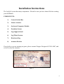
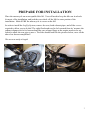
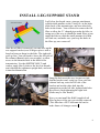
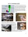
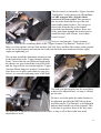
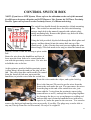
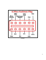
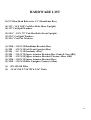
Installation Manual
Victory Vision
Version 2.1
Copyright 2011, Pete Giarrusso, Inc.
D/B/A Chopper Design Services
All Rights Reserved
2
Table of Contents
INTRODUCTION .................................................................................... 4
WARRANTY ............................................................................................ 5
INSTALLATION INSTRUCTIONS ...................................................... 6
COMPONENTS: .................................................................................................... 6
1)
2)
3)
4)
5)
6)
7)
8)
Control Switch Box...................................................................................................... 6
Linear Actuator ........................................................................................................... 6
On-board Computer Module ....................................................................................... 6
Proximity Sensor ......................................................................................................... 6
Leg Support Stand ....................................................................................................... 6
Leg/Wheel System ........................................................................................................ 6
Hardware Bag.............................................................................................................. 6
Actuator Bracket.......................................................................................................... 6
PREPARE FOR INSTALLATION ...................................................................... 7
INSTALL LEG SUPPORT STAND ..................................................................... 8
LEG/WHEEL ASSEMBLY ................................................................................ 13
MOUNT ACTUATOR ......................................................................................... 14
CONTROL SWITCH BOX ................................................................................. 15
WIRING HARNESS .............................................................................................. 17
INITIAL SYSTEM TEST .................................................................................... 20
MOUNT PROXIMITY SENSOR .......................................................................... 21
FINISHING UP ..................................................................................................... 22
ACTUATOR ADJUSTMENT (Maintenance Mode) ....................................................... 23
TEST RIDE ........................................................................................................... 24
LEGUP LITE - ADDENDUM ............................................................................. 26
ILLUSTRATIONS ............................................................................................... 27
Wiring 1 ............................................................................................................................ 27
Wiring 2 ............................................................................................................................ 27
Wiring 3 ............................................................................................................................ 28
HARDWARE LIST .............................................................................................. 29
3
Introduction
This manual covers installation of the LegUp Landingear system by Chopper Design Services.
This system should only be installed by a qualified technician, or those with above average
mechanical skills. If you are not SURE that you can perform this installation, please contact us
and we will help you find a qualified shop to assist you.
If you have been looking for a system that will keep your feet on the pegs, this is NOT the
system for you! On the other hand, if a system that will relieve you of the weight of the bike
and help you avoid balance problems as you approach a stop, LegUp is what you need.
Improper installation will void your warranty, so please be very careful!
Thanks for choosing LegUp!
4
Warranty
Chopper Design Services warrants the LegUp system for a period of one year from date of
purchase. This warranty covers replacement parts and/or manufacturer defects. Incidental
damages or costs are the responsibility of the purchaser.
Defective parts are to be returned to Chopper Design at the address below. Purchaser must
contact Chopper Design to receive a Return Material Authorization, prior to returning defective
parts to Chopper Design.
Abuse, improper installation or use, collisions or accidents, are not covered under this warranty.
Replacement parts for this type of damage are available through Chopper Design.
Users of the LegUp system agree that Chopper Design is NOT responsible for personal injuries
or damage to property arising from the use of the system. While we believe this system to be
safe and reliable, the user is advised that use of LegUp is done so at the users’ own risk. Use of
the system implies agreement to the above statements. If you can’t agree with the above,
Chopper Design and its dealers would be happy to refund your full purchase price, before you
use the LegUp System.
Chopper Design Services
1365 Bennett Dr #101
Longwood, FL 32750
407-834-5007
[email protected]
5
Installation Instructions
The LegUp® system has many components. Pleased be sure you have them all before starting
your installation.
COMPONENTS:
1)
Control Switch Box
2)
Linear Actuator
3)
On-board Computer Module
4)
Proximity Sensor
5)
Leg Support Stand
6)
Leg/Wheel System
7)
Hardware Bag
8)
Actuator Bracket
If you believe you are missing any parts, please contact Chopper Design at 407-834-5007, and
we will rectify the situation.
Figure 1
6
PREPARE FOR INSTALLATION
Place the motorcycle on an acceptable bike lift. You will need to keep the bike on its wheels
for most of the installation, and jack the rear wheel off the lift for some portion of the
installation. Make SURE the motorcycle is secure on the lift!
In order to install the LegUp System, remove the seat, both exhaust pipes, and all the covers
required to allow you to do this! The right floorboard need to be loosened from its’ mounts, the
exhaust clamps need to be loosened and the rear exhaust flange at the engine needs to be unbolted to allow the rear pipe to move. The bike should look like the pictures below, once all the
above has been accomplished!
We are now ready to begin!
7
INSTALL LEG SUPPORT STAND
LegUp has developed a new, stronger attachment
system which attaches to the Victory® via the holes
in the back of the transmission, and two other bolt
holes in the frame. You will need to remove the Oil
filter to allow the ‘U’ shaped pipe under the bike, to
swing out of the way to install the stand. Place a pan
under the bike to catch the small amount of oil that
will leak out, and make sure you keep the holes in
the filter up, once removed!
Once the oil filter is removed, you can offer up the
rear support bracket (two 90 degree pieces with a
long bar between them) to the bike. The right side
goes up first. You will need to lower the left side of
the exhaust (Round circle seen at right), to allow
access to the threaded hole in the back of the
transmission. Use the (METRIC BOLT) and
washer, apply blue Loctite to the last few threads,
run it through the rightmost upright hole, and start
it into the transmission.
Snug this bolt most the way, but not so tight
that the bracket can’t swing up. Now raise the
exhaust back up, raise the left side of the
bracket and run the other bolt into the
transmission on the left side, tighten both bolts.
Here Ben is final tightening the right bolt.
(Bolts may be Hex heads!)
Now you can install the K&N (supplied) oil
filter in place of the one you recently removed.
(This filter has a NUT built onto the end to
make future oil changes easier).
))
8
With the rear support bracket
tightened to the bike, we can install
the support plate. This plate slips
inside the brackets you just installed,
and bolt holes line up between the
two. It is installed with the pipe
(which is offset) up. Once in place,
find 4 3/8” bolts with lock washers,
and start threading them through the
90 degree brackets, into the support
plate. Get all four started, but DO
NOT tighten completely yet!
The next step is to find the front
support bracket, a U-shaped 3/16”
bracket that has two holes on the top
of each arm and two slots on the long bottom. This bracket mounts under the support plate and
attaches to the exhaust mounting bolt on the right side of the bike, and the bolt that secures the
rear brake line on the left. If you haven’t already, remove the bolt that hold the brake line on the
left, and slide the bracket up, aligning the holes on both sides of the bike.
Once in place, start each of the
two ¼” bolts with lock washers
into the slots of the forward
bracket, and start the bolts.
Replace the left bolt by placing
the brake line clamp over the
bracket and start the stock nut
back in. On the right side, the
forward bracket goes on the
outside of the exhaust mount,
and the stock screw runs through
the both pieces. Loctite on these
bolts please!
Now we can tighten up all eight
bolts, as we see Ben doing here.
Now that the support stand is installed, we can move onto the installation of the actuator
bracket.
9
ACTUATOR BRACKET
The actuator bracket mounts to the vehicle
under the left rear crash bar/wing. You will
find two bolts under the middle of the wing.
Remove these bolts (left below) and install
2 long bolts through the ‘Upper Actuator
Mount Front’, then the ‘Upper Actuator
Mount Filler’, into the two holes you just
removed the bolts from. Do NOT tighten
these bolts yet, but do put a bit of Loctite
on them!
The picture above left shows removal of the bolts in
question. The BIG (24MM) nut to the left of the picture
may need to be loosened to let the bolts line up properly.
The picture above
right shows the
orientation of the
‘Filler’ block. Holes
closest to the back,
with the narrow end
toward middle of
the bike. The
picture at right shows Ben aligning the bolts in the
actuator bracket and ‘Filler’. And the picture on the left
shows him attaching the actuator bracket.
10
The next task is to mount the ‘Upper Actuator
Top Bracket’ to the motorcycle. If you have
an ABS equipped bike, skip this entire
bracket as it is not needed. This mounts to
the two bolts that hold the top of the rear
inner fender panel in place. You can get to
these bolts from the top or the bottom
(pictured from bottom). Remove these two
bolts, push them through the bracket and reinstall the bolts with Loctite. Leave them
loose for now!
Next we can hang the ‘Upper Actuator
Support’ from the two remaining holes in the ‘Upper Actuator Top Bracket’. Find two 5/16”
Bolts, two flat washers and two lock washers. Put bolt, lock, and then flat washer on the outside
of the slot in the Support, and start the two bolts into the holes just mentioned (below right).
Again, no tightening yet!
We can now install the aluminum actuator mount
to the back holes in the ‘Upper Actuator Mount –
Front’. Notice this has two different length bolts
the shorter one goes toward the front of the bike,
and the longer to the rear and through the ‘Upper
Actuator Mount Support’ brackets’ bottom hole.
Once these are in place and relatively snug (see
below), we can start tightening most of the bolts.
The bolts you just installed are the most likely
to have to be adjusted later, so snug is all they
get for now.
We have two bolts under the entire bracket to
be tightened, possibly the BIG bolt up front,
two bolts on the ‘Top Bracket’ to be tightened
and two that hold the top of the Support. This
is the time to get these most of the way snug.
We may have to adjust the aluminum bracket later, so any or all of these bolts may need
adjustment as well.
11
Below is the completed Upper Actuator Bracket, installed. The ABS version has just the
actuator mount; the Non-ABS version has the rear support for the bracket. The reason no rear
support is required is the saddlebag guard support on the ABS bikes, is much stronger, so the
extra support is not required.
At this point, MAKE SURE That the BIG 24MM bolt is VERY tight, and that all other
fasteners are tight as well, except the two bolts through the aluminum bracket (snug only!),
which will be adjusted and tightened when we install and align the actuator itself!
On to Mounting the Leg/Wheel Assembly!
NON – ABS
ABS
12
LEG/WHEEL ASSEMBLY
With help from an
assistant, slide the
Leg/Wheel Assembly
around the rear tire (careful
of the finish!), and align
the Leg Mounting Points
(they have the bronze
bushings in them) with the
slots in the Support Stand.
If available a very small
amount of ‘Never Seize’
on the shaft is in order
here. Then start the
stainless steel shaft in from
one side through the tube
on the support stand, and
through the first leg
mounting point and its
bushing. The fit is tight, so take your time. Carefully work the shaft through the tube and the
second leg mounting point. The shaft is inserted properly when it is inserted just past
(approximately 1/8”) the end of the tube. This distance should be about the same on both sides,
but it is not critical as long as both sides are inside the tube. If you need to, you can tap lightly
on the shaft (brass drift is preferred here). Once the shaft is in place, use a small amount of blue
thread locker and install the (2) chrome bolts and washers on the end of the shaft to finish it off.
Make sure the legs move up and down without any binding!
13
MOUNT ACTUATOR
We can now mount the actuator to the Upper
Actuator Bracket we installed a few minutes
ago. The round shaft faces up with the
shorter cylinder facing forward as you can
see at right. A black Allen head axle slides
into the hole in the aluminum mount,
through the actuator and threads into the far
side. You can let the actuator dangle, and
don’t worry about the wire or the plug at this
point. Tighten the bolt!
Next remove the axle from the lower
actuator bracket (the silver piece on the left
side of the left leg). Gently raise the legs and align the bottom hole of the actuator with the hole
in the lower actuator mount, and reinstall the axle. No Locktite yet, as we may have
adjustments! (Don’t forget to remove and Locktite this later!)
NOTE: If the actuator is too short to reach the other mount you may have to lengthen it
using the system. Temporarily plug the
wiring harness into the bike, (as described on
page 16), and follow the directions for
‘Maintenance Mode’ in the ‘Initial System
Test’ section below. Using what would be the
left button on the switch box, just add a small
amount of length to the actuator so you can
align the mounts, then turn the bike back off.
At this point you need to make sure that the
mounts are in alignment and the actuator is
not in any sort of bind! Check from behind
the bike to make sure the actuator looks like it
is in a straight line. It should have slipped into its’ lower bracket easily, without having to bend
the actuator one way or the other. If it did, Great! If not, you may have to adjust the top or
bottom actuator bracket to get everything into alignment. Whatever you have to do to make sure
the actuator is in a straight line now is the time to do it!
On to the Control Switch Box!
14
CONTROL SWITCH BOX
NOTE: If you have a LITE System, Please refer to the addendum at the end of this manual,
for differences between a Regular and LITE Harness! Lite Systems do NOT have Proximity
Sensors. Ignore all references to the Proximity Sensor, it’s Mount and wiring.
The switch box should already be mounted to a black mounting
plate. The switch box mounts above the left switch housing
using a single bolt in the unused (capped with a plastic plug)
mirror mounting hole. Remove this plastic cap, and set it aside;
it will not be re-used here.
Using the bolt provided, slip the bolt through the black plate and
spacer, and then thread it into the mirror hole on top of the
clutch perch. A bit of Loctite here and you can tighten the plate
down snugly! This bolt needs to be snug as when the buttons are
pressed, we don’t want the housing to pivot on the
bolt
Route the wire down the handlebar and leave it
loose near the front forks to be routed under the
seat with the proximity sensor wires. Use wire ties
to hold the wire to the bar.
At this point we need to find the proximity sensor
(yellow thing) & bracket and get the plug off the
end. The wires from this sensor need to be routed
from the front left fork area, up toward the
handlebar, to join the wires from the switch box.
Route the wires under the caliper, and up the fork leg.
Here is the fun part! We need to get the wires from the
front to the area under the seat. You can remove the wires
from the plug on the end of the switch box wire, join
them with the 3 wires from the proximity sensor (plug
removed here as well!), and tape the silver plugs together.
As shown to the above, use a coat hanger or welding rod
and carefully run it from the handlebar area (with wires
taped to it), under the panel to the seat area. You can also
remove the dash pod and run the wires more easily if you like. The plugs may even be able to
stay on (This tip From Doc in Wisconsin!). He says it is a tight fit!
15
Carefully route the two wires out and remove
the pull wire. Once the wires emerge in the area
under the seat, pull on the wires, making sure
they move easily. If not, there is a bind. See if
you can clear this bind, or pull the wires back
out and start over (Sorry!). Once this works out,
carefully remove the tape to expose the silver
pins.
Check the pins to make sure none where
damaged during the process. Make sure the
wires under the fork have enough room to
allow the bars to be turned and that they don’t
get caught on anything.
The next step is to reassemble the plugs. Use the diagram at the start of this section for the
switch box, and the picture below for the proximity sensor.
Be very careful to make sure the wire colors all match those in the mating plug and the diagram.
Now onto the rest of the wiring harness!
The wires from the handlebar control can be tied up neatly at
this point so you will be able to take the extra slack under
seat! The wires from the proximity sensor can be
approximated here, but will be tied off later, and the slack can
be pulled up then.
16
WIRING HARNESS
NOTE: If you have a LITE System, Please refer to the addendum at the end of this manual,
for differences between a Regular and LITE Harness!
The next step is to route the wiring
harness. The harness and the plugs are
routed mostly under the seat, with the
plug (six pin) for the actuator going
down the left side of the bike from
under the seat.
Place the entire harness under the seat
so we can start laying out the wires in
such a way as to not interfere with the
seat.
Run the 12-pin plug into the trunk and
plug the computer into it.
Next we need to run plug in the power wire. On the harness there is an orange wire and a black
wire that have spade connectors attached to
them. Find the gray plug at the front of the
seat area that has a gray wire and a black
wire attached to it. Slide the supplied heatshrink over the orange and black wires and
plug the orange into the plug attaching to
the gray wire, then the black wire to the
black wire on the bike. This gets you the
power required to run the LegUp System.
You can either shrink the heat-shrink, or tie
the ends with wire ties to protect this
connection. Lay the completed connection
into the rubber at the back of the gas tank.
Next we want to plug in the handlebar plug (8-Pin) and the Proximity plug (3-pin). These are
the wires you routed from the front, under the tank. Plug these into their mating plugs. The 3pin connector can be placed into the hollow in the frame (we will be permanently mounting
the Proximity sensor later so the slack will be pulled up once the sensor is mounted
permanently), while the 8-pin plug needs to tuck in above the rubber wire-guide. The concept
here is to get all the wires in such a place as to clear the seat when it is reinstalled!
17
The Picture to the left shows the 8pin plug and the power plugged
placed safely.
The picture at right
shows all the rest of
the wiring placed as
it should be. You will
need to carefully
install and re-install
the seat until you are
sure it goes on and
off properly and the
wires are not being
compromised!
Once you are happy
with this, you can
plug in the actuator
plug (left side), and
leaving a bit of slack
for the actuator to
move up and down,
tie off the wires so they don’t touch anything or bind in any way.
18
Here you can see Ben, Attaching the
Actuator plug in the area below the seat in
front of the left bag, from the bottom.
Once this wire is plugged in, you need to
tie the wires off safely. Basically, we run
the actuator wires against the body of the
actuator, and tie the wires off against the
diagonal bracket that attaches to the upper
actuator bracket.
The picture below shows how this is
accomplished. Notice we left some slack in
the wire so the actuator can move without pulling
on the wire. We also make sure that the wire will
NOT contact the swing arm as it moves up &
down.
The picture below gives you a long shot of the actuator and its’ wires installed properly. Notice
the wire loop toward the back to allow movement of the actuator. Next step; Initial Testing!
19
INITIAL SYSTEM TEST
NOTE: If you have a LITE System, Please refer to the addendum at the end of this manual,
for differences between a Regular and LITE system. Skip this section if you have a LITE
System.
Turn your bike to Accessory Mode. This is the second click on the key on the Vision. The
screen on the dash should light up. At this point, have a look at the yellow proximity sensor
(dangling up front by the left fork, we hope!). The LED Should Not Be Lit. Take a metal object
(screwdriver, wrench, etc) and hold it on the flat face of the sensor (it has a circle embossed in
it). The LED should light up, and go out when you move the metal away. If not, check all your
connections.
Next, press the rightmost pushbutton and hold it for at least 3 seconds. One or both LEDs on the
switch panel should light up; we really don’t care which at this point. If this occurs, you are
doing well. If both LEDs are flashing (maintenance mode) you can skip the next step which is
to press and hold both buttons until both LEDs flash.
Next press both buttons for just an instant! If everything is working, the bottom or yellow LED
on the switch box should flash, and the top LED should be out. The next step, and be careful
here, is to touch the left button for a split second. The legs should move down just a bit. Touch
the right button, and they should move up. With the bike on the lift, you have to be very
careful here!
If all of the above has occurred, raise the legs. Press and hold the right button until the legs
come up all the way, and turn the ignition switch off!
The test is now complete. Let’s move on to mounting the Proximity Sensor.
20
MOUNT PROXIMITY SENSOR
NOTE: If you have a LITE System, Please refer to the addendum at the end of this manual,
for differences between a Regular and LITE system. Skip this section if you have a LITE
System.
This step is crucial!! Understand it before starting. The proximity sensor tells the system
how fast the bike is traveling. The proximity sensor mounts to the bottom of the left front fork.
There are two threaded holes underneath this fork leg. With some Loctite on the two bolts for
the proximity mount, start the two bolts through two lock washers, then the mount and into the
bottom of the fork leg and get them snug
enough to hold the bracket, yet allow for
small movement of this bracket to adjust
the sensor and its’ distance to the rotor
bolts.
You need to jack up the front wheel or have
the bike on the ground so we can spin the
front wheel to test the sensor and its
placement. Make sure the bike is in neutral.
The sensor will track the rotor bolts on the
front wheel as it spins, and is to be mounted
5MM away from the bolts or closer. Look
at the picture at here. Once the bracket is
mounted, turn the bike on, spin the wheel or roll the
bike and watch the behavior of the sensor as the
bolts pass it.
The LED on the sensor should be off when no bolt
is passing the sensor, and the LED should light
when a bolt passes by the sensor. Play with this by
rotating the wheel back and forth while adjusting
the bracket in, out, left or right until the light blinks
consistently (LED is on at right!).
Once you feel you have the right place, tighten the
bracket down and slowly rotate the wheel. Every
time a bolt passes, the light should get bright when
the bolt is nearby and off after it passes.
21
If this is not happening, you may need to get the sensor a bit closer to the bolts (5MM is a very
small distance!). If you have to move the sensor closer, just loosen the bolts again, and re-adjust
the sensor. Bend the metal bracket if you need to; it is stiff enough to stay where you bend it to!
No matter what you need to do, you MUST make sure that as the wheel turns, the light works as
described above! Once you are certain, tighten the bracket down very firmly! Re-check that
everything functions properly by spinning the wheel past all 6 rotor bolts and verifying that the
LEDS changes as described above. The automatic retraction of the legs as well as their
deployment RELIES on this sensor being placed perfectly!
Once satisfied with the mount, make sure the wire running up the fork leg is tied off, clears
everything, and can’t get damaged by anything. The pictures below should help!
22
FINISHING UP
ACTUATOR ADJUSTMENT (Maintenance Mode)
NOTE: If you have a LITE System, Please refer to the addendum at the end of this manual,
for differences between a Regular and LITE system. Skip this section if you have a LITE
System.
Once you have the bike on the ground, turn the ignition to the accessory position and start the
LegUp System (hold right button for 3 seconds). The system should enter maintenance mode
automatically (Both LEDs Flash), but if it does not, enter maintenance mode manually (Both
buttons for 3 seconds). With a helper nearby, straddle the bike, and hold it level. Hit both
buttons for an instant to get the system in the “DOWN” setting mode (yellow LED flashing).
Straddle the bike so your weight is NOT on the seat, hit and hold the left button until the wheels
contact the ground and stop. Make sure that the suspension raises a bit as you do this. If not,
the legs are not going down far enough, the bottom actuator mount may need to be moved left
or right a bit to get the wheels all the way down (Contact LegUp for assistance if you need help
with this). Once these wheels are down as described above, try to put both feet on the
floorboards. The bike should be reasonably stable and you should be able to lean a bit in both
directions without the bike falling over. The DOWN stop is now set!
Hit both buttons for a moment to get into the “UP” stop mode (top LED blinking).
Carefully use the right button to raise the legs. Have your helper let you know as you approach
anything that may come in contact with the wheels or the legs. You also need to make sure the
system clears pipes, clamps etc. If you can’t make the clearance to allow the legs to come up all
the way, you can set the up stop just below whatever is interfering (if not, you will likely set up
a permanent rattle!) Hit both buttons when complete, and you will be done with these
adjustment.
Now press the left button and the legs should lower. Hit it again and the legs should retract. If
you are satisfied with these limits, you have successfully installed the LegUp System. Time for
a test ride!
23
TEST RIDE
NOTE: If you have a LITE System, Please refer to the addendum at the end of this manual,
for differences between a Regular and LITE system. Deployment and Retraction of the
wheels is COMPLETELY MANUAL if you have a LITE System.
Get the bike to a clear paved mostly level area where you can test ride it. Start the bike, turn on
the LegUp system and lower the legs. The first test should be done in a straight line. Put the
bike in gear and slowly accelerate. You may notice that the bike tends to want to steer a small
amount left or right. This is normal unless it is severe. Once underway, the top LED should
flash at around 6 MPH, meaning the legs are retracting. You can lean on one wheel or the other
as you leave to reduce any darting the system may be giving you.
Assuming the legs are retracted, you should try to deploy the wheels. As you come to a stop,
the Green LED should be on. As you slow down (almost stopped), the Yellow LED should
illuminate at the proper speed. Once it does (sometimes hard to see), hit the left button and put
your feet down near the ground. The top LED should flash and you should soon feel the wheels
deploying underneath you! Make sure you are ready to balance the bike! Uneven ground or
lack of familiarity could make the bike want to lean one way or the other. With your feet ready
to balance the bike, this should be no big deal. The slower you are going when deploying the
wheels, the smoother the transition will be from wheels up to wheels down. Practice these
maneuvers until you are comfortable with the wheel adjustments and the system operation.
SEMI-AUTOMATIC DEPLOYMENT: Another way to deploy the legs is to hit the left button
while you are running at any speed over 10MPH with the wheels up. The bottom or yellow
LED should start to flash. When you slow down to around 8MPH the wheels will start to deploy
(see the red/green flash on top LED). Again prepare to put your feet down.
NOTE: The bottom LED Should not be LIT if the legs are up over 10MPH! In
the event it is, the wheels will deploy instantly if you try to set them as above; this
is dangerous! You MUST re-visit the sections on testing the proximity sensor.
You should always be aware that this light should NOT be on if you are traveling
at speed, and ‘Arming’ the system for deployment should only be attempted if the
lower LED is Not Lit! Please see the User Manual for more information on
Proximity Sensor Failure!
24
The next thing to try is to make a turn right after a dead stop with the wheels down. As soon as
you start the bike moving, try a left or right turn immediately by leaning into that turn. You
may find that you have to nudge the bike a little bit more than usual to get the bike to lean, and
you won’t be able to lean as far as you can with the wheels up. Once into the turn, accelerating
will raise the wheels. You will hardly notice the wheels coming up unless you see the top LED
blinking!
The next thing to try is slow speed maneuvering with the wheels lowered. In a straight line on
level ground, you should be able to keep your feet on the floorboards and move the bike
forward at very slow speeds (simulate stop and go traffic). I like keeping my feet near the
ground during these maneuvers! You can also try small ‘Trike’ turns; keeping the bike upright
at slow speed and making turns as you would in a parking lot. Be aware that if you get over the
speed that the legs come up, they will!!! Another thing I like to do is donuts. Start out slow,
lean the bike left or right, and make circles at very slow speeds (throttle on, rear brake on,
clutch slipping… you know like the cops do!). This helps you get familiar with the wheels
being on the springs and allowing a lean angle!
Practice, practice, practice!! Enjoy your LegUp System!
25
LEGUP LITE - ADDENDUM
If you have a Lite System, there are a few differences in the wiring compared to our Regular
system.
The plugs and their locations don’t change at all! Instead of plugging in the computer to the
twelve pin plug, the Relay-Pack gets plugged into this plug. The Relay-Pack will be attached
with Velcro as the computer would have been in the same location.
On the LITE system there is no proximity sensor, so ignore the testing and mounting of this
sensor, and realize that the three pin plug will be left without a mating connector. We keep this
plug in the wiring harness in case you upgrade to a regular system in the future.
Using Your Lite System:
Unlike our Regular System, you don’t turn the LITE system on, or adjust the legs as described
in the ‘Maintenance Mode’ section of the manual. When you turn your bike on, the LITE
system is ready to go! Press and hold the left button to lower the wheels, press and hold the
right button to raise them. No lights will flash; it is up to you to control the system manually!
Please use EXTREME Caution when using the LITE System! Keeping the
wheels lowered at speeds over 9MPH can be dangerous. Since the system is
manual, please don’t allow its’ operation to distract you from controlling the
vehicle!
Upgrading Your LITE System:
If you have a LITE System and have chosen to upgrade it to the regular system, there are just a
few things you need to do. Unplug the Relay-Pack, and plug the computer in where the RelayPack was attached. Run the wire for the proximity bracket and plug it in, test it, and mount it, as
described in the ‘MOUNT PROXIMITY SWITCH’ section of this manual.
Once the new pieces are attached and plugged in, refer to ‘ACTUATOR ADJUSTMENT
(Maintenance Mode)’, earlier in this manual to set the lower and upper stops for the computer.
That’s all it takes!
26
ILLUSTRATIONS
Wiring 1
There are three different types of actuators with three different wiring configurations. Refer to the notes
at the bottom of the pictures above so you can match your actuator with its wiring scheme!
Wiring 2
27
Wiring 3
28
HARDWARE LIST
10-32”Allen Head Bolt cut to 1.3” (Handlebar Box)
(4) 3/8”– 16 X 1.00” Cad Hex Bolts (Rear Upright)
(4) 3/8” Cad Split Washers
(2) 5/16” – 18 X .75” Cad Hex Bolts (Front Upright)
(2) 5/16” Cad Split Washers
(2) 5/16” Cad Flat Washers
(1) M10 – 1.50 X 30 Handlebar Bracket (Hex)
(1) M8 – 1.25 X 30 Left Front Upright (Hex)
(2) M6 – 1.0 X 18 Proximity (Hex)
(2) M8 – 1.25 X 70 Upper Actuator Bracket (Hex Grade 8, Non ABS)
(2) M8 – 1.25 X 90 Upper Actuator Bracket (Chrome Allen, ABS)
(2) M10 – 1.50 X 30 Upper Actuator Bracket (Hex)
(2) M10 – 1.50 X 50 Rear Uprights (Tranny) (Allen)
(1)
(2)
KN-198 Oil Filter
11/16” OD X 7/16”ID X 5/16” Thick
29