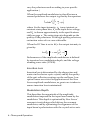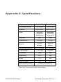
1
USER’S GUIDE Amplitude Modulators Models 4101, 4102, 4103 & 4104 3635 Peterson Way • Santa Clara, CA 95054 • USA phone: (408) 980-5903 • fax: (408) 987-3178 e-mail: [email protected] • www.newfocus.com MASTER Warranty Newport Corporation guarantees its products to be free of defects for one year from the date of shipment. This is in lieu of all other guarantees, expressed or implied, and does not cover incidental or consequential loss. Information in this document is subject to change without notice. Copyright 2012, 2001-1998, Newport Corporation. All rights reserved. The New Focus logo and symbol are registered trademarks of Newport Corporation Document Number 410412 Rev. F Contents Theory and Operation 5 Introduction . . . . . . . . . . . . . . . . . . . . . . . . . . . . . . . . . . . . .5 Theory . . . . . . . . . . . . . . . . . . . . . . . . . . . . . . . . . . . . . . . . .5 Operation . . . . . . . . . . . . . . . . . . . . . . . . . . . . . . . . . . . . . . .7 Customer Service 9 Technical Support. . . . . . . . . . . . . . . . . . . . . . . . . . . . . . . . .9 Service . . . . . . . . . . . . . . . . . . . . . . . . . . . . . . . . . . . . . . . . .9 Appendix I: Linear Amplitude Modulation 10 Appendix II: Specifications 11 Appendix III: Performance Data 13 Amplitude Modulators Contents • 3 4 • Contents Theory and Operation Introduction The New Focus 410X series electro-optic amplitude modulators allow you to achieve deep amplitude modulation of your laser beam with a small input voltage, while maintaining large optical apertures. We offer two types of modulators: • Broadband Amplitude Modulators (AM) for general-purpose applications. • Resonant Amplitude Modulators (RAM) which are tuned to user-specified frequencies. Benefits include low drive voltage, high modulation frequency, low insertion loss, good RF shielding, and high power handling capability. Specifications are show in the table on page 11. The 4101 and 4102 modulators are provided in magnesium-oxide-doped lithium niobate for use in the near 0.5-0.9 µm range. The 4103 and 4104 modulators are provided in lithium niobate for use in the 1.0-1.6 µm range. The user is free to define the modulation frequency of the resonant modulators. Theory The 410X series amplitude modulators require external polarizers at the input and output. Without the external polarizers, these amplitude modulators are actually voltage-variable waveplates. (Polarizers are not provided with the modulators so that you may Amplitude Modulators Theory and Operation • 5 vary the polarizers used according to your specific application. ) When the amplitude modulator is placed between crossed polarizers the output is given by the equation: V I0=Iisin2 -------i- --- + 0 2 V where Ii is the input intensity, 0 is any intrinsic or extrinsic state phase bias, Vi is the input drive voltage, and V¼ is shown approximately in the specifications table on page 11. The extinction ratio depends on the quality of the polarizers. With high-quality polarizers, extinction ratios of 100:1 are achievable. When the DC bias is set to V¼/2 the output intensity is given by: V 1 I0=Ii --- 1 + cos -------i- V 2 Performance of the amplitude modulators is defined by insertion loss, modulation depth, and the voltage standing wave ratio (VSWR). Insertion Loss Insertion loss is determined by the absorption and scatter in the electro-optic crystal, and by the quality of the anti-reflection coatings on the end faces. Low optical losses are critical in applications of the New Focus amplitude modulators, so great care is taken to ensure insertion loss is minimized. Modulation Depth This describes the magnitude of the amplitude modulation imposed on the input laser beam by the modulator. This depth is optimized by New Focus’ resonant circuit design which drives the resonant modulator, and by optimizing the alignment of the input beam’s polarization with the crystal active axis. 6 • Theory and Operation Voltage Standing Wave Ratio (VSWR) The VSWR describes the level of impedance matching between the driving source and the amplitude modulator, which directly affects the power transfer into the device. Resonant amplitude modulators are designed to be very close to 50 Ω at resonance. Thus, they will have a greatly enhanced return loss at the specified resonant frequency. All New Focus resonant amplitude modulators are accurately tested for VSWR by looking at return loss vs. frequency around the modulation frequency. These results are provided at the rear of this manual. Operation Aligning the module to the optical beam: 1. Mount the module on an adjustable positioning device using the 1/4"-20 tapped hole on the base of the module. We recommend the New Focus Model 9071 tilt aligner because of its tilt and translation capabilities. 2. Turn on the optical beam. Orient the beam so it is vertically polarized on the input aperture. The x- and z-crystal axes are oriented ±45° with respect to vertical. Polarizers are not provided with the amplitude modulators. 3. Position and align the module so that the beam passes through the 2-mm input and output apertures, clearing them without clipping. The beam should be collimated with a diameter of less than 2 mm, but such that the Rayleigh range is at least the length of the crystal. A good beam diameter is 200–500 µm. The apertures are made significantly smaller than the crystal cross section to force the optical beam to travel Amplitude Modulators Theory and Operation • 7 through a region of the crystal where the applied electric field is very uniform. Note Since the optical alignment on any modulator can be disturbed by the output cable, ensure that its SMA orientation is not obstructing the alignment and use a strain relief on the cable. Figure 1: A highfrequency resonant modulator driven by a source tuned to fR. The module is mounted on a Model 9071 tilt aligner. POLARIZATION DIRECTION APERTURE SOURCE f = fR Setting Up the Input Signal: Using an SMA cable with a connector, connect the output port on the back of the module to a modulating source appropriate for the type of modulator you are using (resonant or broadband). Resonant modulators are tuned to a specific frequency and require very low drive voltages, such as that from a simple crystal oscillator or a function generator that has an output impedance near 50 Ω. Resonant modulators have a greatly reduced return loss at the specified frequency compared to broadband modulators. Broadband modulators require large drive voltages and have a bandwidth dependent on the impedance of the modulating source. With a 50-Ω source, the bandwidth will be approximately 200 MHz. The source must be able to drive an open circuit without causing damage to the source. 8 • Theory and Operation Customer Service Technical Support Information and advice about the operation of any New Focus product is available from our applications engineers. For quickest response, ask for “Technical Support” and know the model and serial number for your product. Hours: 8:00–5:00 PST, Monday through Friday (excluding holidays). Toll Free: 1-866-NUFOCUS (1-866-683-6287) (from the USA & Canada only) Phone: (408) 980-5903 Support is also available by fax and email: Fax: (408) 987-3178 Email: [email protected] We typically respond to faxes and email within one business day. Service In the event that your modulator malfunctions or becomes damaged, please contact New Focus for a return authorization number and instructions on shipping the unit back for evaluation and repair. Amplitude Modulators Customer Service • 9 Appendix I: Linear Amplitude Modulation 2 πV Sin [ 2V ] π 100 Transmission % Figure 2: The transfer function of an amplitude modulator between crossed polarizers is a sin2 function. Transmitted Intensity 50 Time 0 Modulation Voltage Vπ Applied Voltage Vπ /2 Linear amplitude modulation can be achieved over a limited range by biasing the amplitude modulator at the quarter-wave point which is equivalent to the 50%transmission point. This can be achieved either by applying a DC-bias voltage and a small RF signal to the modulator, or by including a quarter waveplate oriented vertical to the modulator housing. 10 • Appendix I: Linear Amplitude Modulation Appendix II: Specifications Model 4101 Model 4102 0.5-0.9 μm 0.5-0.9 μm Material Mg0:LiNbO3 Mg0:LiNbO3 Type Resonant Amplitude Modulation Broadband Amplitude Modulation 2 mm 2 mm Insertion Loss* <0.3 dB <0.3 dB Max V¼ 19 V @ 633nm 195 V @ 633nm 0.01–250 MHz DC–200 MHz 2–4% freq. 200 MHz Connector SMA SMA Impedance 50 Ω 10 pF VSWR <1.5 -NA- Max. RF Power 1W 10 W Wavelength Range Aperture Operating Frequency RF Bandwidth Max. Optical Intensity <2 W/mm2 @ 532 nm * Insertion loss is wavelength dependent. Amplitude Modulators Appendix II: Specifications • 11 Model 4103 Model 4104 1.0-1.6 μm 1.0-1.6 μm LiNbO3 LiNbO3 Resonant Amplitude Modulation Broadband Amplitude Modulation 2 mm 2 mm <0.3 dB <0.3 dB 30 V 300 V 0.01–250 MHz DC–200 MHz 2–4% freq. 200 MHz Connector SMA SMA Impedance 50 Ω 10 pF VSWR <1.5 -NA- Max. RF Power 1W 10 W Wavelength Range Material Type Aperture Insertion Loss* Max V¼ Operating Frequency RF Bandwidth Max. Optical Intensity * 12 • <1.3 W/mm2 @ 1.3 μm Insertion loss is wavelength dependent. Appendix III: Performance Data Model Number: ___________________________ Serial Number: ___________________________ Frequency: ___________________________ Wavelength: ___________________________ Input RF Power: ___________________________ Return Loss: ___________________________ VSWR: ___________________________ Q: ___________________________ Amplitude Modulators Appendix III: Performance Data • 13 14 • Appendix III: Performance Data