1
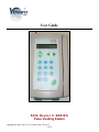
User Guide 5896 Raptor II SERIES Pulse Vending Station Original Rev Date: 04-23-10, Last Rev Date: 30-09-11 1 of 51 Table of Contents 5896-Raptor II Series Pulse Vending Station Operator’s Manual ................................................................ 4 Notice............................................................................................................................................................. 4 FCC Warning................................................................................................................................................. 4 Information to User........................................................................................................................................ 4 One-Year Warranty and Service Policy......................................................................................................... 5 Disclaimer...................................................................................................................................................... 6 Parts and Service Policy ................................................................................................................................ 6 Return Authorizations.................................................................................................................................... 6 About the Product.......................................................7 What is the Pulse Vending Station?............................................................................................................... 7 Vend price structure ................................................................................................................................. 7 System features .............................................................................................................................................. 7 Power failures restore............................................................................................................................... 7 Transaction history................................................................................................................................... 7 Application programming interface (API) ............................................................................................... 7 Setting up the unit.....................................................8 Connecting the unit to the host device ..................................................................................................... 8 Powering up the Pulse Vending Station................................................................................................... 8 Version ..................................................................................................................................................... 8 Location ................................................................................................................................................... 8 Custom Messages..................................................................................................................................... 8 Programming the unit....................................................9 Modifying parameters .............................................................................................................................. 9 Configuring the unit for pulse vending .................................................................................................. 10 Home ...................................................................................................................................................... 11 Parameter listing .................................................................................................................................... 12 Home............................................................................................................................................................ 12 General......................................................................................................................................................... 13 Prices............................................................................................................................................................ 14 VendaCard System Settings - Vend Prices.................................................................................................. 15 Timing.......................................................................................................................................................... 16 Resetting parameters to their default values...........................21 Using a Web browser to reset default parameters: ................................................................................ 21 Multi-Communication Interfaces.........................................22 The VendaCard Control Cards............................................24 VendaCard CODE CARD ........................................................................................................................... 24 VendaCard MANAGER CARD.................................................................................................................. 24 VendaCard PASS CARD............................................................................................................................. 25 VendaCard FORMAT CARD ..................................................................................................................... 25 VendaCard POS CARD............................................................................................................................... 25 VendaCard USER CARD............................................................................................................................ 26 Using the VendaCard CODE Card to set the Site Code.....................26 Using the VendaCard MANAGER Card to set the system Parameters..........27 Using the VendaCard PASS Card to operate the vending device............28 Using the VendaCard FORMAT Card to format user cards...................28 Using the VendaCard POS Card to credit or debit money from user cards..29 Using the VendaCard USER Cards to make purchases.......................30 Using a web browser to set the system parameters.......................31 Logging into the Raptor II Web Server: ...................................................................................................... 31 1) Configuring the network settings using a Network Cable....................................................................... 33 2 of 51 2) Configure the network settings using a cross-over cable ....................................................................... 34 Configuring the Unit...................................................36 Location, Currency, Cash Settings, Date-Time and Others ................................................................... 36 Location ................................................................................................................................................. 36 No Activity Timeout .............................................................................................................................. 36 No Activity Payout................................................................................................................................. 36 Interface ................................................................................................................................................. 36 Defining currency display...................................................................................................................... 36 Currency Symbol ................................................................................................................................... 37 International Currency Code.................................................................................................................. 37 Pre-Cursor .............................................................................................................................................. 37 Max Cash (Not Applicable to 5896) ...................................................................................................... 37 Free Change (Not Applicable to 5896) .................................................................................................. 37 Auto Change (Not Applicable to 5896) ................................................................................................. 37 Coin Return (Not Applicable to 5896)................................................................................................... 37 Disable this unit ..................................................................................................................................... 37 Date/Time............................................................................................................................................... 37 API RS232/USB Baud Rate................................................................................................................... 37 Restore to Factory Default ..................................................................................................................... 37 Determining how VendaCard reader/device operate ............................................................................. 38 MDB Credit Card Reader Settings (Not Applicable to 5896) ............................................................... 38 Status: (Not Applicable to 5896) ........................................................................................................... 38 Enable MDB Credit Card Reader (Not Applicable to 5896) ................................................................. 38 Maximum Pre-Authorized Value (Not Applicable to 5896) ................................................................. 38 Minimum Purchase Value (Not Applicable to 5896) ............................................................................ 38 LCD Msg for Min Purchase Value (Not Applicable to 5896) ............................................................... 38 Reset Credit Card Reader (Not Applicable to 5896) ............................................................................. 38 Determining how cash acceptors operate (Not Applicable to 5896) ..................................................... 38 Coin Changer (Not Applicable to 5896) ................................................................................................ 38 Bill Acceptor/Validator (Not Applicable to 5896) ................................................................................ 38 Pulse Bill/ Coin Acceptor (1 - 6 channels) (Not Applicable to 5896) ................................................... 38 Using the VendaCard System Settings-Vend Prices Menu...................39 To set the price parameters .................................................................................................................... 39 Setting the timing parameters using Timing Menu........................40 Re-configuring timing parameters ......................................................................................................... 40 Timing parameters ................................................................................................................................. 40 About counters/meters..................................................41 Viewing and resetting counters / meters ................................................................................................ 41 Configuring the serial printer.........................................42 Accessing the DB-15HD Interface........................................43 DB-15HD Interface Connector .............................................................................................................. 43 Accessing the Button/Lamp Interfaces...................................44 Molex 12 pin Connector ........................................................................................................................ 44 Error messages.........................................................45 Troubleshooting guide..................................................46 Restoring data after a power failure ....................................................................................................... 47 What is an IP Address? (Static IP, Dynamic IP).........................48 VENDAPIN LLC Product Registration Card.................................49 Contact................................................................52 3 of 51 5896-Raptor II Series Pulse Vending Station Operator’s Manual © 1999-2011 VENDAPIN, LLC. All rights reserved. Printed in the U.S.A. Part number: 400588-002 (current revised: 30-09-2011) Notice The material contained in this manual is subject to change without notice. No part of this manual may be reproduced or used in any form or by any means, electronic or mechanical, including photocopying or electronic transmission or other means of reproduction or distribution without prior written consent of VENDAPIN. The drawings, specifications, and other technical information contained in this manual are the property of VENDAPIN and shall not be copied, reproduced or used in any way, in whole or in part, as the basis of manufacture or sale of similar items without the prior written consent of VENDAPIN. FCC Warning This equipment generates, uses, and can radiate radio frequency energy and if not installed and used in accordance with the instructions in this manual may cause interference to radio communications. This equipment has been tested and found to comply with the limits for a Class A computing device pursuant to Subpart J of Part 15 of FCC Rules, which are designed to provide reasonable protection against such interference when operated in a commercial environment. Operation of this equipment in a residential area is likely to cause interference, in which case the user at her/his own expense will be required to take whatever measures may be required to correct the interference. Information to User This equipment must be installed and used in strict accordance with the manufacturer’s instructions. VENDAPIN is not responsible for any radio or television interference caused by unauthorized modification of this equipment or the substitution or attachment of connecting cables and equipment other than those specified by VENDAPIN. The correction of interference caused by such unauthorized modification, substitution or attachment will be the responsibility of the user. 4 of 51 Two-Year Warranty and Service Policy VENDAPIN LLC. warrants to the purchaser that this VENDAPIN product, hereinafter called “the unit,” is free from defects in materials and the workmanship for a period of two years from the date of purchase. If any such defect is discovered within the first 90 days of the warranty period, VENDAPIN LLC. will repair or replace the unit free of charge. If any such defect is discovered after 90 days and up to the end of the one-year warranty period, VENDAPIN LLC. will repair the unit free of charge plus the cost of shipping. All warranty repair and replacement actions are contingent on verification of the defect(s) or malfunction(s) and upon prepaid delivery of the unit to VENDAPIN LLC., 838 E. Jefferson Street, Brooksville, Florida 34601 by parcel post, common carrier, UPS, Fed Ex, DHL or other commercial means. This warranty does not apply to normal wear, to tampering or alterations resulting in cracked or broken components, or to units damaged by voltage, excessive heat, cold or moisture. To preserve your rights under the warranty, you must provide proof of purchase for the returned unit. RETURNING THE PRODUCT REGISTRATION “CUT-OUT” CARD enclosed in this manual with the new unit will also register the warranty by serving as proof. Otherwise, a copy of the sales invoice showing the serial number of the returned unit must accompany the unit as proof of purchase. If your unit is delivered to VENDAPIN LLC lacking proof of purchase, and we are unable to otherwise verify date of purchase, we will assume the purchase date of the unit was prior to the two-year warranty period. It will then be serviced under the terms of VENDAPIN LLC.'s Service Policy. Our sole and exclusive liability for defects in materials and workmanship shall be limited to repair or replacement of the unit at our service center and we shall not be liable for incidental, contingent, or consequential damages. This warranty does not obligate us to bear any of the costs of transportation charges in connection with repair or replacement of the unit or any defective parts of the unit. This warranty is invalid if the damage or defect to the unit is caused by accident, Acts of God, customer abuse, misuse, unauthorized alteration or repair, or vandalism by third parties. This warranty is made in lieu of any other expressed warranty and except for the foregoing warranty, which is exclusive, there is no other expressed warranty being made. This warranty gives you specific legal rights. You may have other rights, which vary according to the state, or country in which the unit was sold. 5 of 51 Disclaimer This equipment is serviceable by a trained and qualified technician. Parts and Service Policy This policy requires you to ship prepaid to us, the unit or major components of the unit, under a Return Authorization for repair. VENDAPIN LLC shall not be obligated to service or supply parts for any unit after seven years from date of purchase. Charges for return shipping, parts and service will be incurred, as applicable, at the prevailing rates. VENDAPIN LLC will enclose a copy of the return authorization (RA#) with your unit. This authorization details the work performed and the costs incurred. Please refer to the RA# in future communications with VENDAPIN LLC about this unit. Currency acceptors, credit card accessories and standard coin changers are not manufactured or modified by VENDAPIN LLC. These accessories are not included in VENDAPIN LLC’s Warranty or Service policy. Currency acceptors, credit card readers and changers not manufactured or modified by VENDAPIN LLC are warranted and serviced directly by their manufacturer. This policy is for coverage within the continental U.S. only. Return Authorizations All units returned to VENDAPIN LLC must be shipped with a return authorization number (RA#) affixed to the outside of the shipping container and addressed to: Technical Service Department VENDAPIN LLC. 838 E. Jefferson Street Brooksville, Florida 34601 Tel: 352-796-2693 VENDAPIN LLC reserves the right to refuse any incoming shipment not marked with an RA# on the outside of the shipping container. VENDAPIN LLC will issue a Return Authorization Number upon receiving a written request at the above address or a request by phone at +(1) 352-796-2693 (customers should ask for the Technical Service Hotline). Please provide the model number and serial number of the unit or the unit that contained the component(s) you wish to return. For non-warranty service, please be prepared to supply a purchase order, VISA, MasterCard or American Express authorization, or make other payment arrangements as required. Within the continental United States you may request that your serviced unit be returned to you on a C.O.D. basis. 6 of 51 About the Product What is the Pulse Vending Station? The 5896-Raptor II Series Pulse Vending Station is a vending device that works in cooperation with any other device to control access to pools, door locks, or any other device that can be controlled with a relay closure. Customers use VendaCards to pay for their products or services. The Pulse Vending Station is part of VENDAPIN’s Raptor II series, which encompasses a full line of vending products. Vend price structure The Pulse Vending Station supports up to eight vend prices based on products or services patrons pay for with VendaCards. System features Power failures restore In the event of a power failure during a transaction, a power-saving feature saves all data and restores them when power is restored. Transaction history The Pulse Vending Station offers an extensive capability for tracking vending activity. History meters can be viewed using the VendaCard MANAGER card or the integrated web server via web browser. Application programming interface (API) The Raptor II family of Pulse Vending Stations supports an API command set through an on-board USB, RS-232 serial port or Ethernet port that allows you to set parameters, and download meters right from your PC. The API allows the terminal to communicate with a PC while connected to a pulse vend device. This makes it possible to: • Use the Pulse Vending Station with many of the pulse vending devices available today. • Use 5896 systems as the VendaCard payment device attached to the host system. 7 of 51 Getting Started Setting up the unit Connecting the unit to the host device Installation instructions tailored to the product you ordered should have been included with the shipment of your unit(s). Powering up the Pulse Vending Station Plug the 5v DC power supply into the Pulse Vending Station. Then plug the power supply into a wall outlet. The unit cycles through its boot-up sequence, displaying the system version, software version, serial number, and location name. If you ever need to call or email VENDAPIN, LLC customer service, you may be asked to provide this boot-up information. Please note the displayed numbers and write them in the spaces provided on the last page of this manual. Version This is the version of the software that has been issued with your unit. Location Each unit can be configured with the location name. The location name is displayed at boot-up. When the unit is configured at the factory, this parameter is set to “Front Lobby #1”. You should assign each machine at your site a unique location name. This location name is useful when printing the receipts. For information on modifying parameters, see Programming The Unit section. Custom Messages You can customize the unit’s display with the Custom Messages settings. The custom messages can be changed using either the VendaCard Manager card or a web browser connected to the on-board Raptor II built-in web server via Ethernet network. 8 of 51 Your Unit Programming the unit Modifying parameters A set of programming parameters is available to customize the operation of the VENDAPIN, LLC 5896 Pulse Vending Station. When the unit is delivered from the factory, the parameters are in their default state. There are two methods you can use to program the unit: 1. VendaCard Access. Use the five (5) Control Cards to program the 5896. The five control cards are CODE, MANAGER, PASS, FORMAT, and POS. Please see Using the VendaCard Control cards to set the system parameters chapter for details. Figure 1 Front view of the VendaCard 2. Web Access. Use a web browser to connect to the 5896 via network to edit the parameters in real time. Please see Using a web browser to set the system parameters chapter for details. 9 of 51 Figure 2 Raptor II Web Access Showing the List of Menus Screen-shot Configuring the unit for pulse vending Programming parameters are grouped under menus specific to the type of vending operation they apply to. When you enter program mode, you’re presented with the top-level menus (using web browser), in the order shown in Table 1. This method allows you to skip over menus that aren’t applicable to your operation, and to locate specific parameters quickly. 10 of 51 System Menu Home Users General Readers Cash-Credit Card Vend Prices VendaCard System Settings – Vend Prices VendaCard Card Read / Format Timing Product Names Parallel Bill/Coin Coin Changer Coin Changer Tubes Coin Currency Conv. Bill Validator Bill Currency Conv. System LCD Msgs Status LCD Msgs Error LCD Msgs Receipt Printer Net Settings Resettable Meters Non-Resettable Meters System Stats TCP/IP Stats Log Out Pulse Vending Type Description Current System Status Home – Web Login accounts for Raptor II Web server Both print and copy vend operations Print vend operations Not applicable to 5896 Vending Unit Copy vend operations (includes timing menu and price menu) for VendaCard debit cards Shows total number of VendaCard uses and Allows user cards to be formatted (created) Timing Operations for the 8 device channels Name of products 1-8 displayed on the LCD, when they are selected Not applicable to 5896 Vending Unit Not applicable to 5896 Vending Unit Not applicable to 5896 Vending Unit Not applicable to 5896 Vending Unit Not applicable to 5896 Vending Unit Not applicable to 5896 Vending Unit System LCD Messages parameters Status LCD Messages parameters Error LCD Messages parameters Receipt Printer parameters Network settings Resettable counters/meters Non-resettable counters/meters System Status counters/meters Network Status of IP, ICMP, and TCP packets Log Out of 5896 Web Server Table 1 11 of 51 Parameter listing Table 2 through Table 17 lists the parameters in the order they appear on the unit, and also gives the acceptable range of values and default setting for each parameter. Parameter Description Home Main system status Current Date/Time Read Firmware Class Software Version Serial Number Name of location where the system is located. (Editable under General) Displays the system status – ready/disabled/device/etc. Displays the last vend transaction made by the pulse vend system. Displays the last channel transaction made by the pulse vend system Displays the last total paid from vend transaction Displays the last payment used. Three types of payments: Cash, Credit Card or Debit/PIN. Displays the current escrow/balance Displays the last no activity escrow and time-date stamp that the amount was removed from the current escrow/balance. Channel number to add credit to The add or credit can be posted to escrow/balance via web browser. Useful for front desk lobby when the customer reported that the escrow was emptied, or problems with pulse vend that would require credit to be made. dd.mm.yyyy hh:mm:ss System Mode Version S/N Location Status Last Transaction Last Channel Selection Last Total Paid Last Payment Type Escrow/Balance Last No-Activity Escrow Channel# Add Credit Default Range N/A For viewing only For viewing only For viewing only For viewing only N/A N/A N/A N/A For viewing only N/A For viewing only N/A For viewing only N/A For viewing only N/A For viewing only N/A For viewing only N/A For viewing only N/A For viewing only N/A 1 N/A 1 through 8 0-65000 Reset Channel Resets the selected Channel# Unchecked Checked/ Unchecked Print Last Receipt Prints the last receipt – useful if the printer has problems that has been corrected, and would need to print the last receipt as needed Unchecked Checked/ Unchecked Table 2 Parameter Description UserName Users Top level menu settings for user accounts, used for web access only Manager Sets the manager name/password VENDAPIN vendapin Clerk Sets the clerk name/password VENDAPIN password Table 3 12 of 51 N/A Range N/A Parameter Description General Top-level system settings Edits the location name Sets the length of time the unit waits before taking action when a patron has left money. Can be set to pay out change when the no activity timer expires. Location No Activity Timeout No Activity Payout Interface Default Type of user interface for PulseVend. Note: for 5896 vending unit, only the NTS Keypad is used. N/A “Front Lobby #1” 60 (seconds) Unchecked NTS Keypad Sets the currency symbol based on 8 different symbols: Currency Symbol International Currency Code Pre-Cursor Max Cash Free Change Auto Change Coin Return Disable this unit Date/Time API RS232/USB Baud Rate Restore to Factory Default Dollar ($),British Pound (£ ), Yen (¥ ), Euro (€ ), Chile (¢ ), Thailand Baht, Dinar () د, Aruba Florin (ƒ ) or No Currency Sign Symbol Sets the 3 letters international currency code (ISO 4217) to display the 3 letters at the end of the escrow/balance value to appear on LCD screen or print receipt. Sets the currency pre-cursor that will appear on the escrow/balance value. Sets the maximum cash value. Sets to allow the system to dispense change (coin changer) without making any vend transactions. Can be set to dispense change (coin changer) after vend on cash transactions. Can be set to dispense change when the pulse vend times out Sets the system to go into enabled or disabled Sets date and time Sets the baud rate for the serial and USB ports Restores the settings to factory default settings Table 4 13 of 51 Range N/A Up to 20 chars 15-32000 (secs) Checked / Unchecked AutoVend(1 Channel Only), NTS Keypad, Storm Keypad, 8 Push Buttons Dollar ($) Dollar ($) - No Currency Sign Symbol USD Up to 3 chars. Period (.) 9999 (99.99) Period (.), Comma(,) or None 65535 (0 – 655.35) Unchecked Checked/ Unchecked Unchecked Checked/ Unchecked Current Date-Time Checked/ Unchecked Checked/ Unchecked Date-Time 9600 9600, 19200 Unchecked Checked or Unchecked Unchecked Unchecked Parameter Description Readers Top level settings for readers Sub-level settings for MDB cashless/credit card reader Displays the reader status Displays the MDB level Displays the MDB Scale Displays the MDB Timeout Displays the last transaction value Sets to turn on/off the MDB cashless/credit card reader Sets the specific maximum preauthorized value Sets the specific minimum for transactions Sets the LCD display message for minimum purchase value with credit cards MDB Credit Card Reader Settings Status Level Scale Timeout Recently used Enable MDB Credit Card Reader Maximum PreAuthorized Value Minimum Purchase Value LCD Msg for Min Purchase Value Reset Credit Card Reader Default Sets to re-initialize the MDB reader Range N/A N/A N/A N/A For viewing only 0 0 10 For viewing only Unchecked Enabled/Disabled N/A N/A N/A N/A Checked/ Unchecked 25.00 (2500) 1-65535 0 1-65535 Min Purch Value: Up to 40 characters Unchecked Checked/ Unchecked Table 5 Parameter Description Default Range Prices Top level settings for prices N/A Prices 1 – 100 2 – 200 3 – 300 4 – 400 5 – 500 6 – 600 7 – 700 8 – 800 N/A Sets the Cash / Credit Card prices based on the Pulse Interface Mode: Prices 1-8 Total Paid Payment Type - AutoVend (1 device only) NTS Keypad (up to 8 devices) Storm Keypad (up to 8 devices) 8 Push Buttons (up to 8 devices) Edits the total paid message that will appear on the receipt to be printed to printer. Edits the payment type message that will appear on the receipt to be printed to printer. Table 6 14 of 51 1-65535 Note: Every price is based on cents currency system. For example: 10 = 10 cents 100 = $1.00 “Total Paid” Up to 40 characters “Payment Type” Up to 40 characters Parameter Description VendaCard System Settings - Vend Prices Top level settings for prices N/A N/A Site Code Site (location) code for VendaCard system N/A Any eight letter UPPERCASE word Access Group VendaCard security feature in case control cards are lost/stolen 0 0 0 - 255 Enable RFID Reader Check box to enable the use of the VendaCard reader Checked Checked or Unchecked. Auto-Reset Card Resets the VendaCard system after each transaction with a Card Checked Checked or Unchecked. Card Timeout Amount of time in seconds that the VendaCard will timeout if a transaction is not made Vend Prices using VendaCard 1-8 Sets the price based on the Pulse Interface Mode: - Default Range AutoVend (1 device only) NTS Keypad (up to 8 devices) Storm Keypad (up to 8 devices) 8 Push Buttons (up to 8 devices) Table 7 15 of 51 3600 Prices 1 – 100 2 – 200 3 – 300 4 – 400 5 – 500 6 – 600 7 – 700 8 – 800 0-65535 Seconds 1-65535 Note: Every price is based on cents currency system. For example: 10 = 10 cents 100 = $1.00 Parameter Description Default Range VendaCard ReadFormat Top level settings for reading and formatting VendaCards N/A N/A VendaCard RFID Card Data Read Sub-level settings for reading VendaCard RFID data N/A N/A SiteCode/Created Date Site (location) code for the VendaCard inserted. Date the VendaCard was formatted For viewing only N/A Group Level Security encoded on the VendaCard For viewing only N/A Total Card Uses Total number of times the VendaCard was formatted For viewing only N/A Current Escrow/Balance Balance currently on the VendaCard For viewing only N/A Format VendaCard Sub-level settings for formatting VendaCard RFID data RFID Cards N/A N/A Access Group Level Security code to be encoded on the VendaCard 00 0 - 255 Escrow 0 0 -9999 Escrow/Balance to be encoded on the VendaCard Note: Every price is based on cents currency system. For example: 10 = 10 cents 100 = $1.00 # of VendaCards to Format Total number of VendaCards you wish to 10 format 0 - 9999 Cancel VendaCard Card Format Now Stop formatting VendaCards Checked / Unchecked Unchecked Table 8 Parameter Description Timing Top level settings for timing parameters Selects the FDI (Foreign Device Interface) to use: - AutoVend (1 device only) - NTS Keypad (up to 8 devices) - Storm Keypad (up to 8 devices) - 8 Push Buttons (up to 8 devices) Minimum debit pulse length for input pulses (all FDI modes) Mode Channel Timer Default N/A Range N/A NTS Keypad AutoVend, NTS Keypad, Storm Keypad, 8 Push Buttons 1250mS 1-32000 milliseconds Table 9 Parameter Description Default Product Name Messages Top level settings for Product Names displayed on the LCD Product Name 1 - 8 Sets the Product Name LCD messages to be displayed when a product is selected 16 of 51 N/A Range N/A Up to 20 characters Product Name 1 – Product Name 1 2 – Product Name 2 3 – Product Name 3 4 – Product Name 4 5 – Product Name 5 6 – Product Name 6 7 – Product Name 7 8 – Product Name 8 Table 10 Parameter Description Default System LCD Messages Top level settings for System LCD Messages 1st line Idle state Sets the 1st line – idle message, state 1 2nd line Idle state 1st line Idle state 2 2nd line Idle state 2 1st Please make your (Credit Card Only) 2nd selection (Credit Card Only) 1st line Escrow/Balance 1st line Please Remove nd 2 line Your VendaCard 2nd line Press Enter Key 1st line RFID Card 1st line Total Sales (Credit Card Only) 1st Cash N/A Range N/A Up to 20 characters Sets the 2nd line idle message, state 1 “VENDAPIN LLC” “PulseVend Series” Sets the 1st line idle message, state 2 Sets the 2nd line idle message, state 2 “Insert Coin” “Bill or Card” Up to 20 characters Up to 20 characters Sets to display the credit card message after the approval is made. “Please make your” Up to 20 characters “Selection.” Up to 20 characters “Escrow/Balance:” Up to 20 characters “Please Remove” Up to 20 characters “Your VendaCard” Up to 20 characters “Then Press ENTER” Up to 20 characters “VendaCard” Up to 20 characters “Credit Card” Up to 20 characters “Cash” Up to 20 characters Sets to display the credit card message after the approval is made. Sets to display the Escrow message only when there is positive cash balance available for vends. Sets to display the “Please Remove” message Sets to display the “Your VendaCard” message Sets to display “Press Enter” message Sets to display the remove message for the RFID card Sets to display “Credit Card” message, used for credit card transactions. Sets to display “Cash” message, used for receipt printing. Up to 20 characters Table 11 Parameter Description Default Status LCD Messages Top level settings for Status LCD Messages System – Ready Sets the System – Ready message Enabled Sets the Enabled message Disabled Exceeded Limit Bypass Mode Total Sales (Credit Card In Use) Approved (Credit Card Only) Declined (Credit Sets the Disabled message Sets the Exceeded Limit Message Sets the Bypass Mode Message Sets the Total Sales Message, used for credit card transactions Sets the Approved message, used for credit card transactions. Sets the Declined message, used for 17 of 51 N/A “System-Ready” “Enabled” Range N/A Up to 20 characters Up to 20 characters “Disabled” “Exceeded Limit” “Bypass Mode” Up to 20 characters Up to 20 characters Up to 20 characters “Total Sales” Up to 20 characters “Approved” Up to 20 characters “Declined” Up to 20 characters Card Only) credit card transactions. Table 12 Parameter Description Error LCD Messages Top level settings for Error LCD Messages Error Message Unable to read card Insufficient! Invalid Account Out of Service Not In Use Use Exact Coins Out of Coins Default Sets the error message to appear on 1st line Sets the Bad Card message, used for RFID/swipe card reader Sets the Insufficient funds available message Sets the Invalid Account message Sets the Out of Service message, used for payment devices reporting the error messages Sets the Not in Use message, used for payment devices not currently installed in the vending unit Sets the Use Exact Coins message, used for when the coin acceptor has less than $1 in change Sets the Out of Coins message, used for when the coin acceptor runs out of change, while dispensing change to customer Table 13 18 of 51 N/A “*Error Message*” “Reader is Offline” Range N/A Up to 20 characters Up to 20 characters “Insufficient!” Up to 20 characters “Invalid Account” Up to 20 characters “Out of Service” Up to 20 characters “Not in Use Up to 20 characters “Use Exact Coins” Up to 20 characters “Out of Coins” Up to 20 characters Parameter Description Receipt Printer Top level settings for serial Receipt Printer Use Printer LCD Message Line #1 (Web) LCD Message Line #2 (Web) Credit Card Only Special Start Hex Printer Delay Start Header LineFeeds Print Test Receipt Header 1-8 Footer 1-5 End Footer LineFeeds BarCode Initization BarCode Print Code Special End Hex Chars Default Sets the printer service to Disabled, AutoPrint or Manual (button) Sets the “Press Button to” LCD message for print services Sets the “print receipt” LCD message for print services Sets to print the receipt only if credit card is used. Sets the hex codes used for logo Sets the Printer Delay to allow for brief pause for every printed line Sets the Start Header Line Feeds Test the receipt printing Sets the Header messages to appear on the receipt Sets the Footer messages to appear on the receipt. Sets the End Footer Line Feeds Sets the bar code Initialization codes (00 if not used) Sets the bar code print codes (00 if not used). The 7F char is used for inserting the purchase details. Set the hex codes used for paper cutter N/A Disabled “Press ANY KEY” Range N/A Disabled, AutoPrint or Manual (Button) Up to 20 characters “to Print RECEIPT” Up to 20 characters Unchecked Checked/ Unchecked 1BFA01000002F0 30 (mS) 2 Up to 20 characters 1-65535 mS 0-65535 Unchecked Checked/ Unchecked Messages Up to 40 characters Messages Up to 40 characters 4 0-65535 1D6824 Up to 10 chars 1D6B067F00 Up to 10 chars 1CC034 Up to 10 chars Default Range Table 14 Parameter Description Net Settings Serial Number IP Address Network Port Web Port Subnet Mask Gateway Top level settings for Network Settings Factory configured value Sets the IP Address Sets the network port number Set the web access port number Set the Subnet Address Sets the Gateway Address MAC Displays the MAC Address Use Net API Allows use of the network Application Programming Interface Server Host IP Address Server Network Port Restart Network Sets the Host Server's IP Address Sets the Host Server's Network Port Restart the network services based on the current network settings N/A For viewing only 192.168.1.100 1234 8080 255.255.255.0 192.168.1.1 Hardware MAC (For viewing only) Unchecked 192.168.1.98 4321 Unchecked N/A N/A IP4 format Up to 65535 Up to 65535 IP4 format IP4 format N/A Checked/ Unchecked IP4 format Up to 65535 Checked/ Unchecked Table 15 Parameter Description Default 19 of 51 Range Meters Channel 1-8 Cash Bills Coins Credit Card Bypass Vends No Activity Escrow Taken (No Activity) PC-Web Debits PC-Web Credits Cash → Account Transfer Clear Resettable Meters? Last Cleared Top level menu for meters (resettable and non-resettable) Displays the total vend counter for each channel Displays the total cash value (cash and bills) Displays the total cash value (bills only) Displays the total cash value (coins only) Displays the total credit card purchases Displays the total value of vends using the PASS card Displays the total no activity counters Displays the total escrow value taken as resulted from the expired no activity timer Displays the total debits made by host Displays the total credits made by host Displays the total amount of Cash transferred to an account card Allows resettable meters to be zeroed Shows the date and time that the Resettable Meters were last zeroed N/A N/A For viewing only N/A For viewing only N/A For viewing only For viewing only For viewing only N/A N/A N/A For viewing only N/A For viewing only N/A For viewing only N/A For viewing only For viewing only N/A N/A For viewing only N/A N/A N/A For viewing only N/A Table 16 Parameter Description System Stats Top level menu for system stats (resettable and non-resettable) Displays the total transactions All Transactions Invalid Transactions Card Swipes Transactions via Net Transactions via Serial Power-Ups Printed receipts Cards Formatted POS Card Uses Clear Resettable Stats? Last Cleared Default Displays the total invalid transactions Displays the total credit card swipes Displays the total transactions done by network (web access) Displays the total transactions done by serial (RS-232 or USB) Displays the total power-ups Displays the total printed receipts Displays the total number of VendaCards formatted Displays the total number of times the POS Card was used Allows resettable statistics to be cleared Shows the date and time that the Resettable Meters were last zeroed Table 17 20 of 51 Range N/A N/A For viewing only For viewing only N/A For viewing only N/A For viewing only N/A For viewing only N/A For viewing only For viewing only N/A N/A For viewing only N/A For viewing only N/A N/A N/A For viewing only N/A N/A Resetting parameters to their default values Using a Web browser to reset default parameters: 1. Log into Raptor II web server using your web browser with known IP address/port number. Note: Default IP address/port number is – http://192.168.1.1:8080 2. Log in Raptor II Web access using the Manager account. Note: Default passwords are shown in table 3. 3. Click on the General link 4. Check the Restore to Factory Default checkbox. 5. Press the Restore button. Figure 3 21 of 51 Multi-Communication Interfaces Communication VENDAPIN’s Raptor II multiple communication interfaces make use of Ethernet, USB or RS-232 for API communication service connected to a host system in real-time. The details for each interface are described here for reference. Ethernet Interface Details: TCP/IP Network protocols: Raptor II Ethernet service has a built-in HTTP web server and TCP/IP socket server. The API commands used by Raptor II Ethernet service are based on socket TCP/IP network communication protocol. The configurable network port number is required to access the Raptor II socket server in order to receive the formatted response packets based on the specific API command packet. (Example: 192.168.1.100 1234 for TCP/IP socket network access to Raptor II). Note: If either USB or RS-232 API commands are issued, the network connection will be disconnected automatically for security purpose. To access the Raptor2 using the network, simply re-connect the client access to the Raptor2 web server and issue API commands as normal. HTTP Web Server: Raptor II has a built-in web server that would allow access to all functions and parameters used by the Raptor II API commands. This web service is an excellent tool to allow the developer to test the API commands and then compare the results listed on the web pages generated by the Raptor II web server. This feature is also used as secondary access when the host system is off-line. Features: • HTTP port number: Required in order to access the Raptor II HTTP web server. Example: for access to Raptor II Web server: http://192.168.1.100:8080 ◦ Note: 192.168.1.100 is the default IP address ◦ Note: 8080 is the default web port number • Account levels: Manager and Clerk. ◦ Manager has read/write access to all functions and parameters. ◦ Clerk has “read only” access to all services, except for “post credit” function. • The network settings are configurable by web services or API commands. Web Access Usernames/Passwords Manager Username: VENDAPIN Manager Password: vendapin Clerk Username: VENDAPIN Clerk Password: password Manager Username: vendapin (Backup if the manager username and/or password are lost.) Manager Password: vendy123 22 of 51 USB Interface Details: The USB interface used by Raptor II requires an USB driver (provided by VENDAPIN) to be installed on the host system. The USB drivers are available for Windows, Mac OS9/X and Linux. The USB drivers will allow for the USB port to be treated as the “virtual COM” port to allow the host system to interface to the Raptor II USB port. The Raptor II USB port is treated as a “slave” device, just like a mouse or keyboard and cannot operate as a “host/master” USB port, per USB specifications (see http://www.usb.org for details). USB Drivers Installation for 5896 Series: Before you plug the Raptor II USB port into a multi-port or single port USB bus, please ensure that you have followed these requirements: 1. Make sure that the power cord(s) and USB cable(s) for the 5896 system(s) are unplugged. 2. Insert the API Raptor II Setup Express CD in the cdrom drive. 3. If plugging in more than one (1) 5896 system into a USB port, please make sure that the multiple USB cables connected to the 5896 systems are plugged directly into PC USB ports or use buspowered (not self-powered) multi-port USB hub connected to PC. 4. When installing the USB drivers, please use the USB drivers that come with the API Raptor II Setup Express CD. The USB drivers, can be found in the USB Drivers folder on the CD. The “standard” Microsoft USB drivers may not work when dealing with multiple USB 5896 systems. 5. Start with one USB 5896 system connection and complete the USB driver installation first. Then install the additional USB 5896 coin-op driver installation(s) ONE at a time until the USB drivers for all USB 5896 systems are properly installed. 6. To avoid mixing up the Raptor II USB port(s) connected to multiple USB port(s) on the PC, make sure the cable(s) are labeled. 7. Set the baud rate for the USB port(s) to 19200. RS-232 Interface Details: The RS-232 serial communication interface used by Raptor II does not require any drivers. The default RS232 communication protocol for 5896 systems is: 19200, 8, N, 1 and no handshaking. The RS-232 serial port is also used for interfacing to the optional receipt printer. 23 of 51 Accessing Using the VendaCard Control Cards The VendaCard Control Cards A set of 5 (five) VendaCard Control Cards allow configuration and setup of the VENDAPIN, LLC 5896 Pulse Vending Station. VendaCard CODE CARD Figure 4 shows the VendaCard CODE card. This card is used to set the SiteCode of the 5896. The SiteCode programs the 5896 to only allow VendaCard User cards for one company or location. This prevents VendaCards from different companies or locations to be used at your location. Figure 4 VendaCard MANAGER CARD Figure 5 shows the VendaCard MANAGER card. This card is used to configure the 5896 Pulse Vending Station system settings. Figure 5 24 of 51 VendaCard PASS CARD Figure 6 shows the VendaCard PASS card. This card allows unlimited free pulses on all channels for testing and demonstrations. Figure 6 VendaCard FORMAT CARD Figure 7 shows the VendaCard FORMAT card. This card allows the 5896 to format blank user cards or reformat corrupted user cards. Figure 7 VendaCard POS CARD Figure 8 shows the VendaCard POS card. This Point Of Sale card allows money to added (credit) or subtracted (debit) from user cards. Figure 8 25 of 51 VendaCard USER CARD Figure 9 shows the VendaCard USER card. This card is used by the customers to make a purchase with the 5896 Pulse Vending Station. Figure 9 Using the VendaCard CODE Card to set the Site Code Figure 4 shows the VendaCard CODE card. Insert the VendaCard CODE Card into the 5896 Pulse Vending Station. The site code will be set as shown in Figure 10. The 5896 Pulse Vending Station will beep and set the Site Code for your location. Remove the VendaCard CODE Card. Figure 10 26 of 51 Using the VendaCard MANAGER Card to set the system Parameters Figure 5 shows the MANAGER Card. Insert the VendaCard MANAGER Card into the 5896 Pulse Vending Station. The 5896 Pulse Vending Station will show the network settings as shown in Figure 11. Remove the VendaCard MANAGER Card. Figure 11 Use the up and down arrows on the keypad to cycle through the system settings: Counters/Meters Network Devices/Services General Settings Date – Time Prices Timing Interfaces Exit Use the Return key to make a selection. Select EXIT and press the Return Key, when you are done with the system settings. 27 of 51 Using the VendaCard PASS Card to operate the vending device. Figure 6 shows the PASS Card. Insert the VendaCard PASS Card into the 5896 Pulse Vending Station. The 5896 Pulse Vending Station will show the Bypass Mode as shown in Figure 12. Figure 12 While the VendaCard PASS Card is inserted all pulse station(s) will be active Remove the VendaCard PASS Card when you are done to return the 5896 Pulse Vending Station to normal operation. Using the VendaCard FORMAT Card to format user cards. Figure 7 shows the FORMAT card. Insert and remove the VendaCard FORMAT Card from the 5896 Pulse Vending Station. The 5896 Pulse Vending Station will show the Credit Value: window as show in Figure 13. Figure 13 Use the keypad on the 5896 Pulse Vending Station to set the initial value on the card. Note: $0.00 is the default value. Press the Return Key on the keypad The 5896 Pulse Vending Station will show the Cards to Format window as show in Figure 14 28 of 51 Figure 14 Use the keypad on the 5896 Pulse Vending Station to enter the number of cards to format Press the Return key on the keypad Insert the first USER Card to format. When the Formatting Done Window appears remove the user card. Continue inserting more cards until all cards are formatted. Using the VendaCard POS Card to credit or debit money from user cards Figure 8 shows the POS card. Insert and remove the VendaCard POS Card from the 5896 Pulse Vending Station. The 5896 Pulse Vending Station will show the Debit Value: screen. Figure 15 If you wish to credit money to the user card, use the plus arrow on the keypad to show the Credit Value: screen. See Figure 15. Press the number keys to enter the value to be debited or credited to the user card. Press the Return Key on the keypad. 29 of 51 Using the VendaCard USER Cards to make purchases Figure 9 shows the USER card. Insert the VendaCard USER Card into the 5896 Pulse Vending Station. The display will show the amount of credit available on the card. See Figure 16. Figure 16 The user can now use the 5896 Pulse Vending Station as long as the card is inserted and contains sufficient value. 30 of 51 Accessing Using the Web Using a web browser to set the system parameters A convenient way to configure the Pulse Vending Station parameters, in real-time, is to use a web browser. Logging into the Raptor II Web Server: Figure 17 shows the login screen after you open a web browser to access to Raptor II via network: Figure 17 The factory default accounts for manager and clerk are as following: Manager: Username: VENDAPIN Password: vendapin Clerk: Username: VENDAPIN Password: password NOTE: The manager and clerk accounts passwords should be changed immediately for security purposes. After you log in, you will see the Main Menu with Home web page as shown by default as shown in Figure 18. 31 of 51 Figure 18 Raptor II Web Access Main Menu The left column of Figure 18 contains the top-level menu selections. The right side of Figure 18 displays the details of the top-level menu selected. The top-level menus are described in details under the Your Unit chapter. There are two methods to configure the IP, Subnet Mask, and Gateway addresses: 1. Configure the network settings using a network cable Note: This method requires that 192.168.1.100 is not in use. 2. Configure the network settings using a cross-over cable Note: This method is useful if 192.168.1.100 is already in use. 32 of 51 1) Configuring the network settings using a Network Cable Obtain the following information from your IT department: an unused “static” IP Address Subnet Mask Gateway Address Network Port Web Port Determine your computer's network settings: On Windows XP, click Start Click run type in cmd Click OK In the Command Prompt window, type ipconfig and press the Enter key The following information will be displayed pertaining to your computer IP Address Subnet Mask Default Gateway. Type exit and press the Enter key to close the Command Prompt window. If your computer's IP Address is 192.168.1.X (Subnet is: 255.255.255.0, Gateway is 192.168.1.1, which is typical), you can configure the 5896 network settings by opening a web browser. Open a web browser Type http://192.168.1.100:8080 into the address bar and hit the Enter key. The Raptor II Login Window will now be displayed. - Log in using the Manager account. - Click on Net Settings (on Raptor II Web access) - Change the IP, Subnet and Gateway addresses. - Click Restart Network checkbox - Press the Save button. 33 of 51 2) Configure the network settings using a cross-over cable Note: These instructions were written assuming Windows XP as the installed operating system. 1. Unplug the network cable from your desktop (or laptop). 2. Right mouse click on the Local Area Connection Icon next to the clock. See figure 19 Figure 19 3. In the Network Connections Window, Right mouse click on the Local Area Connection icon. See figure 20 Figure 20 4. Click on Properties 5. In the Local Area Connection Properties, select Internet Protocol (TCP/IP) 6. Click on the Properties button. See figure 21 Figure 21 7. In the Internet Protocol (TCP/IP) Properties, select the General tab 8. Select the Use the following IP address radio button. See figure 22 34 of 51 Figure 22 9. Enter 192.168.1.1 for the IP address. 10. Subnet mask should be 255.255.255.0 11. Click OK 12. Click Close 13. Close the Network Connections window 14. Plug in the Crossover Cable. 15. Open a web browser 16. Type http://192.168.1.100:8080 into the address bar and hit the Enter key. 17. The Raptor II Login Window will now be displayed. 18. Log in using the Manager account. 19. Click on Net Settings 20. Change the IP, Subnet and Gateway addresses. 21. Click Restart Network checkbox 22. Press the Save button. 23. Change your PC network settings back to the original settings and save the network settings. More details about the IP address use can be found at the end of the manual. 35 of 51 Configuring the Unit Configuring the Unit for VendaCard Operation Location, Currency, Cash Settings, Date-Time and Others The following parameters are located under the General Menu. Location This is the where the 5896 Pulse Vending Station is located. It is useful to set this value to tell apart 5896 Pulse Vending Stations, when multiple stations are present. No Activity Timeout This is the amount of time, between 1 second and 65,535 seconds, during which nothing will happen when a patron has left an escrow in the unit. • If there is escrow alone in the unit immediately after the vend or deposit was made, the No Activity timer has started. Then the fate of that escrow depends on how the No Activity Payout parameter is set (see below). Setting the No Activity timer Set the parameter for the amount of time the unit should wait before taking action. Disabling the No Activity timer Setting No Activity Timer to 0 will disable the no activity timer. No Activity Payout This parameter is available only if No Activity is set. It determines what happens to the escrow when the no activity timer expires. • • If checked, the unit pays the balance If unchecked, the escrow is absorbed by the unit and added to the No Activity meter. Interface This parameter sets the interface based on the type and number of devices. At default, the interface is set to AutoVend, which uses the FDI (Foreign Device Interface) to connect the opto-relay circuit to enable/pulse vend operations. Please contact VENDAPIN if you require different interfaces. Defining currency display The following parameters are located under the General Menu. They determine how currency (Example Currency format: $1.00USD ) appears on the display and in printouts as described here: 36 of 51 Currency Symbol Set this parameter to specific currency symbol to display the currency symbol character next to currency. The existing currency symbols are listed here: • Dollar ($) • British Pound (£ ) • Yen (¥ ) • Euro (€ ) • Chile (¢ with 2 forward diagonal lines) • Thailand Baht (β with vertical line in middle) • Dinar () د • Aruba Florin (ƒ ) • No Currency Sign Symbol International Currency Code Set this parameter to configure the 3-letter international currency code (ISO 4217) to be displayed after the currency value. Pre-Cursor This parameter selects two currency separators (comma or period) or none. This separator will be seen in all menus, displays, and printouts. Max Cash (Not Applicable to 5896) This is the maximum cash value a patron can insert into the cash acceptance device. The maximum cash value is $655.35. Free Change (Not Applicable to 5896) If this parameter is checked, the unit will act as a change machine. Auto Change (Not Applicable to 5896) This parameter determines whether change is paid out after a cash transaction is performed. Coin Return (Not Applicable to 5896) This parameter enables or disables the coin return option. Disable this unit This parameter allows the manager or clerk to disable the unit remotely. Date/Time Set this parameter to configure the real-time date and time clock. The real-time date-time clock is used for time-date stamp on all transactions. API RS232/USB Baud Rate This parameter controls the speed of the serial ports (RS232 and USB) on the 5896 Pulse Vending Station Restore to Factory Default Set this parameter to restore all parameters to Factory Default. 37 of 51 Determining how VendaCard reader/device operate The following parameters are located under the Readers Menu. Use them to configure for specific parameters for the VendaCard reader/device. MDB Credit Card Reader Settings (Not Applicable to 5896) The parameters in the Readers Menu govern all credit card transactions. Status: (Not Applicable to 5896) This parameter determines if the credit card reader is activated. Enable MDB Credit Card Reader (Not Applicable to 5896) This parameter determines if the credit card reader is to be activated. Maximum Pre-Authorized Value (Not Applicable to 5896) This parameter determines the maximum amount that the credit card reader sets aside until the final bill is settled. Minimum Purchase Value (Not Applicable to 5896) This parameter determines the minimum amount that the credit card user will be charged per transaction. It is recommended that this value be set high enough to cover credit card transaction fees. LCD Msg for Min Purchase Value (Not Applicable to 5896) This is the display parameter that notifies the customer of the minimum value that will be charged to their credit card. Reset Credit Card Reader (Not Applicable to 5896) This parameter allows the credit card reader to be reset. Determining how cash acceptors operate (Not Applicable to 5896) The following parameters are located under the Coin Changer, Bill Validator and Parallel Bill/Coin Acceptor Menus. Use them to configure for specific parameters for these coin and bill acceptors. Coin Changer (Not Applicable to 5896) The Coin Changer Menu incorporates parameters for enabling/disabling international currency values. Bill Acceptor/Validator (Not Applicable to 5896) The Bill Validator Menu incorporates parameters for enabling/disabling international currency values. Pulse Bill/ Coin Acceptor (1 - 6 channels) (Not Applicable to 5896) The Pulse Bill/Coin Acceptor can be plugged in the parallel bill/coin port on Raptor II board and then configure the pulse values for each channel. 38 of 51 Setting Pulse Vending Prices Using the VendaCard System Settings-Vend Prices Menu The 5896 Pulse Vending Station allows up to 8 prices depending on the interface mode. To set the price parameters 1. Click on the VendaCard System Settings-Vend Prices link. Figures 23. 2. Configure the prices 1-8 based on device connected. 3. The price parameters that are displayed will depend on the operating mode the machine is in. Figure 23: Web Browser – Price Settings 39 of 51 Coordinating Timing with the Device Setting the timing parameters using Timing Menu Re-configuring timing parameters The timing parameters in the Pulse Vending Station should be set to match the timing requirements of the vending device. (These values should be published in the host product’s documentation.) If you’re experiencing problems that indicate that the timing is off between the VENDAPIN system and host-vending device, try fine-tuning the timing parameters. To modify the timing parameters 1. Select Timing Menu. 2. Change the timing parameters appropriate to the particular symptom you’re witnessing. Timing parameters Channel Timer (1-8) This parameter is set in 1-millisecond increments, ranging from 1 to 65535 milliseconds. At default, the 1250mS time value is used. This is the minimum length of time a pulse will remain active. 40 of 51 Using Counters/Meters About counters/meters All vending activity is recorded with an extensive set of internal electronic meters. There are two sets of meters available: • Resettable meters. Allow for periodic recording of transactions. They are usually viewed, then reset on a regular basis. • Non-resettable meters. Provide a tamper-proof record of all transactions made on the system. Viewing and resetting counters / meters You can view, reset, and print the meters in a web browser, using the System Stats selection. 41 of 51 Configuring the serial printer Setting up a Printer You can hook up a portable printer to the Pulse Vending Station to print out receipts. Figure 24 Rear Unit DB-9 Female Serial Port 1. Connect a serial printer to the DB9 port (See Figure 24) on the back of the controller board. 2. The printer should be configured to operate with the parameters listed in Table 18. Read the printer user’s manual that accompanied the serial printer to find out how to set them. 3. Configure the Copy Vending Station using a Web browser and set the Receipt Printer parameters under Receipt Printer menu. Printer Serial Settings Baud Rate: Parity: Data Bits: Stop bits: Flow Control: 19200 None 8 1 None Table 18 42 of 51 Accessing the DB-15HD Interface FDI Interface DB-15HD Interface Connector VENDAPIN, LLC’s Vending Access Control products use a DB-15HD connector to interface with thirdparty vending devices. The DB-15HD connector is a VENDAPIN, LLC standard for interfacing to system devices. Pre-assembled harnesses with installation instructions from VENDAPIN, LLC are available. Figure 25 Rear Unit DB-15 Interface Female Connector Table 19 shows the pinout settings for the DB-15HD connector. Pinout for J2 DB-15HD Interface Connector PIN Description 1 2 3 4 5 6 7 8 9 10 11 12 13 14 15 GND Opto1 Monitor Line 1 Input Opto1 Monitor Line 1 Output N/A (Not Used) Enable Relay 2 N/O N/A (Not Used) N/A (Not Used) N/A (Not Used) Enable Relay 2 COMMON Enable Relay 1 N/C Enable Relay 1 COMMON Input Source for Driver to Onboard Resistors N/A (Not Used) Enable Relay 2 N/C N/A (Not Used) Enable Relay 1 N/O Shield Ground – Not Connected, Used for Return Loop Table 19 43 of 51 Button/Lamp Interface Accessing the Button/Lamp Interfaces Molex 12 pin Connector VENDAPIN, LLC's Pulse Vending Control products can also use the two Molex 12 pin connectors to interface with up to eight third-party vending devices. Each Molex 12 pin connector is a VENDAPIN, LLC standard for interfacing with up to four pulse vend products using a relay assembly. By using both connectors a total of eight pulse vend products can be controlled using a relay assembly. Pre-assembled harnesses with installation instructions from VENDAPIN, LLC are available. Pinout for J13 and J14 Molex 12 pin Interface Connectors PIN Description 1 Ground 2 Button 1 / Button 5 3 Button 2 / Button 6 4 Button 3 / Button 7 5 Button 4 / Button 8 6 Lamp 1 / Lamp 5 (pull to ground) 7 Lamp 2 / Lamp 6 (pull to ground) 8 Lamp 3 / Lamp 7 (pull to ground) 9 Lamp 4 / Lamp 8 (pull to ground) 10 +5v DC 11 +12v DC (Not Available on 5896 vending unit) 12 +24v DC (Not Available on 5896 vending unit) Table 20 Note: The Lamp lines can only support 350 mili-amps. If you need more current capacity, then an external relay MUST be used. 44 of 51 Error Messages, Troubleshooting & Misc. Error messages LCD Message Cause Solution Out of Service The bill acceptor/coin changer is disabled because the software has received a full, jam, or stacker open message from them. This message appears only once, when the event occurs. Remove all money and clear the bill and coin path of foreign objects. Exceeded Limit The escrow in the machine, plus the last bill inserted exceeded the unit’s cash limit. The bill is ejected. Insert a smaller bill or coins. The Max Cash parameter can be increased, to prevent this from occurring Out of Coins Use Exact Coins Declined The unit is holding escrow because there is not enough money in the coin tubes to pay out the requested change. The bill acceptor is rejecting the notes The purchase price has exceeded the maximum preauthorized value. Table 21 45 of 51 Refill the coin tubes. Refill the coin tubes. Increase the maximum pre-authorized value and contact the merchant account to increase the limit. Troubleshooting guide Pulse Vending Station problems Table 22 describes problems that may occur in the Pulse Vending Station, and provides the steps you should take to resolve the behavior. Problem Cause Solution • No letters on LCD display screen • LCD screen intensity too low. • System problem. • No main power to unit. • • • All blocks on LCD display screen • LCD screen intensity too high. • System problem. • Reset condition. • • • Serial port or USB port not working • Wrong baud rate. • Wrong cable. • • Table 22 46 of 51 Adjust the LCD display contrast using the trimpot (clockwise) located on bottom/front/right side of board next to LCD connector. Power down for few seconds, then power up again (unplug & replug the unit power cord from electrical outlet). Check electrical fuse. Adjust the LCD display contrast using the trimpot (counterclockwise) located on bottom/front/right side of board next to LCD connector. Power down for few seconds, then power up again (unplug & replug the unit power cord from electrical outlet). Contact VENDAPIN technical support. Host and Print/Copy Vending Station must be set to same baud rate (19200). Use standard off-the-shelf 9-to-9 serial cable. Re-install USB drivers and check the COM port on host machine. Restoring data after a power failure In the event of a power failure during a transaction, the unit will save the following information. • Escrow amount • All last transactions When the unit regains power, the data listed above is restored. If there was escrow before the power outage, that amount will be restored and the display updated. The patron can then continue with the transaction. 47 of 51 What is an IP Address? (Static IP, Dynamic IP) An IP address identifies a computer or other network attached device to the network. Every device on a network needs to have its own unique address. That way, data is sent to the correct device. There are global IP addresses that are used by the whole Internet and local IP addresses that are only used behind a router. Q: Why isn't there One Set of IP Addresses for the Whole World? A: It might be nice if every computer had its own IP address. Unfortunately, computers are replaced frequently — millions are added, removed, or rearranged every day. It would be impossible for everyone in the world to keep up with the changes. To avoid this problem/ the Internet community does a number of things: - They use one set of global addresses for the whole world. - A group of private address spaces were set aside for use in a private network behind a router. - Some addresses are used only temporarily. When the computer is turned off, the address is given to someone else. - Subnet masks were created to break large networks into smaller more manageable groups. Whether for the whole world, or just for your home or office, an IP address always looks like this (four numbers separated by three periods): 192.168.1.1 The subnet mask has the same format. The subnet masks on your own home network will almost always have exactly these numbers: 255.255.255.0 Don't change the subnet mask without being sure what it does! You need to keep a record of these IP addresses: 1. The one your IT department gives you. This one is used by the whole world to access your network. 2. The address of your 5896 unit on your own network. By default VENDAPIN sets the IP address to 192.168.1.100. That's the IP address you type in an Internet browser to log in your 5896 unit. 3. There are situations where you will need to know IP addresses of other devices in your network. What's the Difference Between Static and Dynamic IP Address? The IP addresses from your IT department are assigned one of two ways: - Static IP address. The device is assigned an IP address that never changes. - Dynamic IP address. The device is assigned a temporary IP address, which can change according to the policy set by your IT department's DHCP router. Because a Static IP address does not change, most networking equipment requires a static IP. Dynamic IP addresses are used in large networks where computers are frequently reconfigured or moved. 48 of 51 VENDAPIN LLC Product Registration Card 1 Year Warranty To better serve our customers, we are enclosing a “cut-out” Warranty Registration card here, which when filled out and returned to VENDAPIN LLC, will permanently register your equipment for warranty repairs and technical services. VENDAPIN Model Number: Serial Number: Software Type: Revision: Ship Date: Company Name/Location Address: City/State/Zip: Phone: Email: Purchased From: Host Machine (Copy/Print Machine) Make/Model Received in good condition? Problems installing? System satisfactory? Suggestions or problems: 49 of 51 NOTES 50 of 51 Contact Corporate & Manufacturing Offices: 838 Jefferson Street Brooksville, Florida 34601 Tel: +1.352.796.2693 Fax: +1.775.256.6311 [email protected] [email protected] [email protected] Technical Support and R&D: [email protected] Web Site: www.VENDAPIN.com