1
ELECTRONIC VALVE CONTROLLER IV
SET UP INSTRUCTIONS
PART # 4503-RA006
4503-RA009
IMPORTANT! Read all instructions before attempting to set up the EVC IV.
When you begin the implementation, read through each step again.
1. TO BEGIN: On the back of the EVC unit is a switch marked “SW< >PO". If you have a single port, swing valve or internal type
wastegate, select "SW". If you have a dual port, poppet or external type wastegate, select "PO".
2. LEARNING MODE: The learning mode will enable the EVC IV to read your vehicle's normal boost curve. This information will
widen your car's power band in order to optimize the benefits of your turbo. For safety reasons, we recommend going to a local
drag strip to set the learning mode. With the power on, push and hold the "Alt" button. While holding the "Alt" button push the
"Sbc" button. The unit should emit an audible beep and the display should show an "L" for "Learning Mode". The EVC IV is now
ready for your first test run. IMPORTANT! Do not engage boost until the car is in third gear! This will produce maximum load on
the vehicle. Starting at 2000 rpm, accelerate under boost until an audible beep is heard. After the beep, lift off the throttle. The
EVC IV has learned the vehicle's stock boost. (If a beep is not heard before red line, the vehicle is not producing stable boost.
Check all hose connections and verify proper installation).. After the, first test pass is completed, the EVC display should now read
"H". The EVC is now ready for your second pass. Again, do not engage boost until third gear. Starting at 2000 rpm, accelerate
under boost until red line is reached. Once the throttle is lifted, an audible beep will be heard. The "Learning Mode" was
successful, and the EVC N will go directly into the "Boost Pressure Setting" mode. You can now skip down to step #5. If you have
trouble setting the learning mode, you can skip this step and go directly to step #3 below. Due to the varying transitions between
twin sequential systems (such as the Supra Twin Turbo and RX7 Twin Turbo), it is recommended to bypass the learning mode.
3. STOCK BOOST SETTING: If you do not have an HKS boost gauge or do not know your vehicle's stock boost, you must do the
following: With "Low' and "Set" flashing, turn the EVC's volume knob counterclockwise until the display reads 0.00, then press
"Sbc". Enter 0.20 and press "Sbc" again. Drive the vehicle under full boost in third gear and read the boost pressure once it
stabilizes. This figure is your stock boost. Reset the EVC unit (see directions on the next page). Once the unit has been reset,: when
"Low" and "Set" are flashing, enter your stock boost pressure, followed by pressing the "Sbc"button.
Note: If at any time during the set up process the display flashes "L" or "H"; it is an indication that you need to calibrate the
volume knob. If a flashing "L" is displayed, turn the volume knob all the way counter clockwise. If a flashing "H" is displayed, turn
the volume knob all the way clockwise.
4. STOCK BOOST "PLUS" SETTING: In order to input your "stock boost plus", you must add .2 to your stock boost number. For
example, if you entered .5 (7.25 psi) as your stock boost, you must input.7 as your boost plus setting
(.5 + .2 = .7). With "High" and "Set" flashing, turn the volume knob until your stock boost plus setting is displayed, then press the
"Sbc" button.
Note: IF YOU HAVE ANY PROBLEMS AND WANT TO START AGAIN, YOU CAN RESET THE UNIT. With he ignition key in
the on position and the power to the unit turned off, push and hold the "Mod" button. While holding the `Mod" button, push and hold
the "Alt" button. Then while holding both "Mod" and the "Alt" buttons, push and hold the `Sbc" button. You should hear an audible
beep. You can then go back to instruction #1 above. If you do not hear a beep, your unit may not have presets programmed in the unit.
5. BOOST PRESSURE SETTINGS: The unit will display "high" while "set" is flashing. Turn the volume knob until the desired boost
number appears. Immediately push the "Alt" button. The unit will display "low" while flashing "set". Turn the volume knob until
the desired boost number appears. Immediately push the "Mod" button.
IMPORTANT: Your "high" setting must be equal to or higher than your "low" setting. If a flashing “?????”
displayed during this process of setting the boost pressures, you must recalibrate the volume knob. Please refer to the
bold print in step #3 for re-calibration directions.
6. OFFSET MODE: This function enables you to calibrate your boost levels.
If you have completed the "Learning Mode", the offset should automatically be calibrated. You can verify by pushing the "Mod"
button (see flow chart). If the display reads "100", your "offset mode" is correct and you can now advance to instruction #7.
If you have not completed the "Learning Mode", you may need to calibrate the boost levels by adjusting the "Offset Mode". For
example if you have a single port, swing valve or internal type wastegate and have programmed the EVC for a "low boost" of 1.0 but
it will only hit .9. The "Low Offset Setting" allows you to adjust the offset in order to match your programmed number. In the
example above if we dial the offset number down from 100 to 86, the readout for the boost you achieve should now match your
programmed low boost of 1:0. Be sure to follow the instructions below for the specific type of wastegate you are using. There are
two offset modes. One for the "high" boost setting and one for the "low" boost setting. Program the offset using even numbers only
and between the range of 50 - 150. The default or normal setting is "100". To calibrate your "Offset Mode", follow only one set of
instructions listed below.
Dual port, poppet or external type wastegates If the
display shows a lower boost than what you had
programmed, raise the offset number. If the display shows a
higher boost than what you had programmed, lower the
offset number.
Single port, swing valve or internal type wastegates If the
display shows a lower boost than what you had programmed,
lower the offset number. If the display shows a higher boost
than what you programmed, raise the offset number.
7. SCRAMBLE BOOST SETTING: This setting allows you to run higher boost for a predetermined length of time simply by pushing
the "Sbc" button. The additional scramble boost and time settings will be the same for both the high boost and low boost. To gain
access to this function push the "Mod" button. The display should read "0.00". Input the amount of additional boost to be
programmed by turning the volume knob. For example, if your boost is set at 1.1 and you want to be able to run at 1.3 for a short
duration of tire you would dial in.2 (1.1 + .2 =1.3).
8. SCRAMBLE TIME SETTING: This mode will set the duration of time the "Scramble Boost" will stay in effect. You can program
this function to operate from 1 - 30 seconds. Push the "Mod" button. The display should read 00. Program the time duration for 1-30
seconds by turning the volume knob.
9. WARNING BOOST SETTING: This mode is a safety feature that will act as an override in the case of an overboost condition. When
triggered the EVC IV display will flash, set off a series of audible beeps and return your boost back to the stock level until you lift off
of the throttle. For example: if your high boost setting is 1.1 and you want the warning boost setting to be .1 over your high boost
setting you will set this mode at 1.2 (.1 + 1.1 = 1.2). To access this mode push the "Mod" button then dial in your setting by turning
the volume control knob.
10. AUTO ADJUST MODE: Over a period of time as your turbocharger begins to wear and becomes less efficient, the boost pressure
may drop. This mode allows the EVC IV to automatically adjust the wastegate in order to maintain the boost pressure. WARNING!!
Because this mode will cause the turbo to work harder in order to produce the same boost pressure it will contribute to the turbo's
deterioration. For this reason we recommend that the "Auto Adjust Mode" be turned off.
To turn the "Auto Adjust" mode off, make sure the ignition key is on and the EVC power is off. While holding the "Mod" button,
change the "SW< >PO" switch on the back of the unit from its current position. Once you hear an audible beep return the switch
back to its original position. Again there will be an audible beep. To turn the "Auto Adjust" mode back on, simply repeat the same
step above.
1. INHIBIT MODE: Inhibit mode enables the EVC IV to be locked so that none of the preset values can be changed. To engage the
inhibit mode, make sure the ignition key is on and the unit po wer is off. While holding down the "Alt" button change the position
of the "SW< >PO" switch on the back of the EVC. Release the "Alt" button and return the switch back to its original position. The
presets are now locked into the EVC N. To turn the inhibit mode off, make sure the key is in the on position and the unit power is
off. While holding down the "Sbc" button, change the position of the "SW< >PO" switch on the back of the unit. Release the "Sbc"
button and return the switch back to its original position. Inhibit mode is now turned off and all of your presets and programming
can be changed.
EVC IV FLOW CHART
(How to advance between functions after initial set up)
®1997, HKS U.S.A., INC.
bar to PSI Conversion Table
ELECTRONIC VALVE CONTROLLER IV
INSTALLATION INSTRUCTIONS
PART # 4503-RA006
NOTICE
Read this entire manual to understand how the EVC IV functions before beginning the installation process. Do not attempt to
Install or adjust the EVC IV without thorough knowledge of how this unit works. This manual assumes that you have the
knowledge in the operation of tools and equipment that are necessary to safely perform service operations on your vehicle. This
manual also assumes that you are familiar with typical automotive systems and basic service and repair procedures. Always have
access to a factory repair manual as some of the procedures and specifications required for the proper installation of this product may
be referenced to the factory repair manual. To avoid the risk of personal injury, follow the lifting, supporting, and safety -precautions
contained in the factory repair manual.
USER NOTES
• The EVC IV can be used on both internal and external wastegate type turbochargers.
• The EVC IV is not capable of reaching boost levels lower than stock (OEM) levels.
The EVC IV will maintain it's programming even if the vehicle's battery is disconnected or the head unit is unplugged.
The serial numbers must match on the controller and the stepping motor in order for the unit to function properly.
The EVC IV is a sensitive electronic component and must be handled with extreme care. Miswiring or shock will damage the unit. Do not place
near extreme heat, water, or areas prone to dirt and dust.
Most factory turbocharged vehicles come equipped with a secondary boost limiting system (fuel-cut system or pop-off valve) to safeguard
against wastegate failure. Due to this, the EVC IV alone will not be able to raise the boost pressure beyond the point of the factory limit. If this
condition occurs, consult your HKS distributor for information regarding products that can assist in this situation (HKS Fuel Cut Defencer,
HKS Vein Pressure Converter, HKS Programmed Fuel Computer, etc.).
If the vehicle has a fuel cut defense system such as the HKS FCD, make certain that the vehicle's boost pressure is not raised excessively , as this
will lead to engine and/or turbocharger damage. HKS will not warranty any damage caused be excessive boost levels.
Make sure the vehicle has a proper fuel management system that can handle higher boost pressures than stock (OEM) levels. HKS will not
warranty damage caused by improper fuel management (lean air/fuel ratio).
The EVC IV cannot control boost pressure above the maximum efficiency point of the turbocharger. Boost pressure drop at high rpm may not
be totally eliminated. The EVC IV will not be able to compensate for pressure loss due to turbocharger sizing. Boost creep or boost spikes due
to inadequate wastegate flow capacity, lean air/fuel ratio, poor compressor design, or excessive backpressure may not be fully alleviated.
Increasing the boost pressure will also increase the intake air temperature. If the intake air pressure exceeds 220 degrees Fahrenheit (100 deg.
Celsius), performance increases may be minimal and detonation may occur.
For best performance and to safeguard against detonation, always use the highest octane gasoline available (92-octane minimum).
Do not rely on the factory boost meter (if equipped) when adjusting the maximum boost pressure. Install an HKS auxiliary boost pressure meter
to monitor manifold boost pressure levels.
The utilization of an HKS exhaust gas temperature (EGT) meter is recommended to monitor engine conditions (rich or lean air/fuel ratios).
Mount the EVC IV control unit and harness away from high-power two-way radios, mobile phones, and their respective antenna cables to
prevent malfunction of the EVC IV unit.
CONTROL UNIT DIAGRAM
1.
2.
•
•
Disconnect the negative battery cable from the battery.
EVC stepping motor installationDetermine an ideal mounting location for the stepping motor.
Mount the stepping motor to the chassis using the hardware provided with this kit.
•
Do not install the stepping motor close to the exhaust manifold or any area of high temperature.
•
Do not install the stepping motor where it will be exposed to water or moisture.
•
•
3.
•
Ports 1, 2, and 3 must face upward with port number 4 pointing down.
Lengths on all hoses must be kept as short as possible.
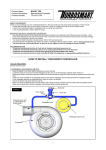
Vacuum Filter InstallationInstall vacuum filters per diagram to the right. Make sure the filters are within I 0cm (3.9") length from the stepping motor.
•
The 6mm vacuum filter should be installed with the short side facing the stepping motor.
•
Inspect the filters every 3000 miles. They must be clean for the EVC to function correctly. If the filter is contaminated or dirty,
replace with a new one. Do not attempt to clean the vacuum filter. If the filters frequently need replacement, relocating the pressure
source may solve the problem.
4. Connect the red wire (2-pin harness) from the EVC to a 12-volt ignition source. Utilizing a voltmeter, find a wire that receives at
least 12 volts with the key in the "IGNITION" position.
5. Connect the black wire (2-pin harness) from the EVC to a chassis ground. Make sure there is no paint or rust on the ground
surface. If there is, sand the surface until bare metal is exposed.
•
Determine if the vehicle is equipped with an internal wastegate (single port actuator) or an external wastegate, or dual port
actuator, then proceed to the corresponding installation instructions.
INTERNAL WASTEGATE (SINGLE PORT ACTUATOR) INSTALLATION INSTRUCTIONS
Port #1- Connect to an uninterrupted intake manifold
pressure source after the throttle body such as a compressor
bypass signal line using the 4mm hose.
• Do not connect port #1 to the line that operates the fuel
pressure regulator unless the supplemental instructions
tell you to do so.
• This hose should be as short as possible and should not
exceed 100cm (3'4").
• Install the 4mm vacuum filter within l0cm(3.9") of
port #1 on the EVC stepping motor.
Port #2- Connect to a source of pressurized air such as a
turbocharger compressor housing (discharge side) or
compressor outlet pipe (before the intercooler) using the
6mm hose.
• This hose should be as short as possible and should not
exceed 100cm (3'4").
• Install the 6mm vacuum filter within l0cm (3.9") of
port #2 on the EVC stepping motor.
Port #3- Connect to the port on the wastegate actuator.
• This hose should be as short as possible and should not
exceed 100cm (3'4").
Port #1- Connect to an uninterrupted intake manifold pressure source after the throttle body such as a compressor bypass signal line using the 4mm
hose.
• Do not connect port #1 to the line that operates the fuel pressure regulator unless the supplemental instructions tell you to do so.
• This hose should be as short as possible and should not exceed 100cm (3'4").
• Install the 4mm vacuum filter within l 0cm (3.9") of port #1 on the EVC stepping motor.
Port #2- Connect to a source of pressurized air such as the turbocharger compressor housing (discharge side) or compressor outlet pipe (before the
intercooler) using the 6mm hose. Use the tee fitting supplied with this kit to connect a pressure line to the secondary port on the wastegate actuator.
• Both lines should be as short as possible and should not exceed I 00cm (3 '4").
• . Install the 6mm vacuum filter within l 0crn (3.9") of port #3 on the EVC stepping motor.
Port #3- Connect to the port on the wastegate actuator. 0 This hose should be as short as
TROUBLESHOOTING
Note: If at any time the EVC does not reset or readjust, make sure the unit is not locked in "INHIBIT" mode (see setup
instructions).
EVC Control Unit Will Not Illuminate:
•
Power Connection- There must be a constant 12-volt power source under all conditions with the ignitio n "ON".
•
Ground Connection- In some cases, paint, rust, or a loose bolt will cause a bad ground.
•
Electronic Splice Connector- Visually from the outside, wire connections may look good. In some cases, the wires are not making contact inside
the connector. Check the wires at both ends with a voltmeter to ensure continuity.
EVC Will Not Control Boost:
•
Make sure the SW<>PO switch on the back of the unit is in the correct position.
•
Check the hose connections to ports 2 & 3 on the EVC stepping motor. EVC III, IV, and EZ stepping motors differ from EVC I and II stepping
motors (see installation diagrams).
•
Check for continuity at each wire on the 8-pin harness for possible breaks in a wire. If the pins on the main harness were disconnected while
running the harness through the firewall, make sure that the wire colors match the EVC control unit plug.
Vehicle Is Not Building Enough Boost (Underboosting):
•
Make sure the stock boost solenoid is disconnected.
•
Check for possible improper adjustment of the EVC unit. Read the manual again to verify that you are following the correct procedure.
•
The vacuum filters (4 & 6mm) may be clogged or dirty.
NOTE: With additional engine modifications, you must update the self-learning data (The unit must be reset and the le arning
mode must be implemented once again).
Vehicle Is Building Too Much Boost:
•
Verify that there are no leaks in the hoses, and that all connections are tight. Check for hose damage such as pinholes or tears.
•
Make sure the vacuum filters (4 & 6mm) are not cracked.
•
Wastegate valve may be too small or actuator may be too weak.
•
Turbocharger capacity may be too small (In this case, the boost curve will drop off during high rpm compared to the factory boost curve).
NOTE: With additional engine modifications, you must update the self-learning data (The unit must be reset and the learning
mode must be implemented once again).
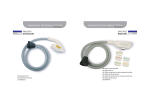
PARTS LIST
HKS U.S.A., Inc. LIMITED WARRANTY
Warranty Policy
HKS U.S.A., Inc. ("HKS") warrants to the original retail purchaser that the HKS product
will be free from defects in material and workmanship for one (1) year from the date of original
purchase except for:
• Full stainless steel exhaust and piping, which are warranted for four (4) years
from original purchase.
• Turbochargers and wastegates, which are warranted for one hundred twenty
(120) days from original purchase.
• Clutches, which are warranted for ninety (90) days from original
purchase.
This warranty does not apply where:
the product has been used for competition/racing,
• the product has been abused, misused, improperly maintained,
• repairs have been made or attempted by others,
• repairs are required because of normal wear and tear,
• alterations have been attempted or made to the product,
• the product is a consumable,
• the product has been in an accident.
This warranty is limited to repair or replacement, without charge, of the product/part
found to be defective or, at HKS' option, refund of the purchase price and does not extend to
claims for other loss or damage arising from the defect. If a part or component from an HKS
system/kit is found to be defective, this warranty shall apply only to the defective part or
component and shall not require HKS to repair, replace or refund the complete HKS system/kit.
In no event shall HKS' liability under this warranty exceed the purchase price of the HKS
product.
This warranty does not include the cost of removal or reinstallation of the product. No
person or representative is authorized to extend any warranties on behalf of HKS (other than
expressed herein) or assume for HKS any liability (other than expressed herein) in connection
with the sale of any HKS product.
HKS DISCLAIMS ANY AND ALL LIABILITY FOR ANY IMPLIED WARRANTIES, INCLUDING
THE IMPLIED WARRANTIES OF MERCHANDABILITY AND FITNESS FOR A SPECIFIC PURPOSE.
UNDER NO CIRCUMSTANCES SHALL HKS BE LIABLE FOR ANY INCIDENTAL, INDIRECT,
SPECIFIC OR CONSEQUENTIAL DAMAGES ARISING FROM PURCHASER'S USE OF THE
PRODUCT.
Some states do not allow one or more of the above specified exclusions or limitations. This
warranty gives you specific legal rights and you may also have other rights, which vary from
state to state.
Effective 4/01
(See other side for Claims Procedure)
HKS U.S.A., Inc. LIMITED WARRANTY
Claim Procedure
To make a claim under this warranty you must: 1. Working with the HKS U.S.A., Inc. Authorized
Dealer, make every attempt to determine the problem attributed to the HKS product. Please take
all steps to ensure that the problem is not caused by:
• installation error
• misapplication
• modification
• abuse
• accident
An inspection fee will be charged for all products sent to HKS for inspection and found
to be in proper working order or malfunctioning due to cause other than manufacturing defect:
• Electronics
$120.00
• Non-electronic
$70.00
2. If the problem cannot be identified, obtain a Return Goods Authorization (RGA) number
through the HKS Authorize Dealer from whom you purchased the product. Retain the RGA
number for reference.
3. Send the product freight and/or postage prepaid, to HKS USA Warranty Claims
Department, 2801 East 208th Street, Carson, CA 90810-1102. Please:
• Clearly mark the RGA number on the outside of the package and the mailing
label - PACKAGES WITHOUT THIS INFORMATION WILL BE RETURNED.
• Include a copy of your original invoice showing the; a. A detailed
description of the problem b. A list of ALL
modifications to the vehicle c. Part number d.
Date of purchase e. The purchase price f. Your
name and address g. Daytime phone number
HKS is not responsible for products returned to HKS without a clearly marked RGA number
and return address.
Please allow 6-8 weeks for inspection and determination of warranty claim.
Should the dealer no longer be an Authorized HKS Dealer, or no longer be in business, you
should contact HKS U.S.A., Inc. directly.
~ee other side for Warranty Policy)
Effective 4/16/0