1
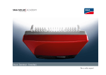
PV Inverter
SUNNY MINI CENTRAL
9000TL / 10000TL / 11000TL
9000TL / 10000TL / 11000TL with Reactive Power Control
Installation Guide
SMC9-11TLRP-IEN100640 | IME-SMCTL_9_10_11 | Version 4.0
EN
SMA Solar Technology AG
Table of Contents
Table of Contents
1
1.1
1.2
1.3
1.4
Notes on this Manual. . . . . . . . . . . . . . . . . . . . . . . . . . . . . .
Validity . . . . . . . . . . . . . . . . . . . . . . . . . . . . . . . . . . . . . . . . . . . .
Target Group . . . . . . . . . . . . . . . . . . . . . . . . . . . . . . . . . . . . . . .
Additional Information . . . . . . . . . . . . . . . . . . . . . . . . . . . . . . . .
Symbols Used . . . . . . . . . . . . . . . . . . . . . . . . . . . . . . . . . . . . . . .
2
2.1
2.2
2.3
Safety . . . . . . . . . . . . . . . . . . . . . . . . . . . . . . . . . . . . . . . . . . 9
Appropriate Usage . . . . . . . . . . . . . . . . . . . . . . . . . . . . . . . . . . . 9
Safety Instructions . . . . . . . . . . . . . . . . . . . . . . . . . . . . . . . . . . . 11
Explanation of Symbols . . . . . . . . . . . . . . . . . . . . . . . . . . . . . . 12
2.3.1
Symbols on the Inverter. . . . . . . . . . . . . . . . . . . . . . . . . . . . . . . . . . . . . . . . . 12
2.3.2
Symbols on the Type Label . . . . . . . . . . . . . . . . . . . . . . . . . . . . . . . . . . . . . . 12
3
3.1
3.2
Unpacking. . . . . . . . . . . . . . . . . . . . . . . . . . . . . . . . . . . . . . 14
Packing List . . . . . . . . . . . . . . . . . . . . . . . . . . . . . . . . . . . . . . . . 14
Identifying the Inverter . . . . . . . . . . . . . . . . . . . . . . . . . . . . . . . 15
4
4.1
4.2
4.3
Installing the Device . . . . . . . . . . . . . . . . . . . . . . . . . . . . . . 16
Safety . . . . . . . . . . . . . . . . . . . . . . . . . . . . . . . . . . . . . . . . . . . . 16
Selecting the Mounting Location. . . . . . . . . . . . . . . . . . . . . . . . 16
Mounting the Inverter with the Wall Mounting Bracket . . . . . . 18
5
5.1
Electrical Connection . . . . . . . . . . . . . . . . . . . . . . . . . . . . . 21
Overview of the Connection Area . . . . . . . . . . . . . . . . . . . . . . 21
5.1.1
Exterior View . . . . . . . . . . . . . . . . . . . . . . . . . . . . . . . . . . . . . . . . . . . . . . . . . 21
5.1.2
Interior View . . . . . . . . . . . . . . . . . . . . . . . . . . . . . . . . . . . . . . . . . . . . . . . . . 22
5.2
Connection to the Public Grid (AC) . . . . . . . . . . . . . . . . . . . . . 24
5.2.1
5.2.2
Conditions for the AC Connection . . . . . . . . . . . . . . . . . . . . . . . . . . . . . . . . 24
Connecting the Inverter to the Public Grid (AC) . . . . . . . . . . . . . . . . . . . . . . 26
5.2.3
Additional Grounding of the Housing. . . . . . . . . . . . . . . . . . . . . . . . . . . . . . 28
Installation Guide
SMC9-11TLRP-IEN100640
7
7
7
7
8
3
Table of Contents
SMA Solar Technology AG
5.3
5.4
5.5
Setting the Display Language . . . . . . . . . . . . . . . . . . . . . . . . . . 29
Installing the String Fuses . . . . . . . . . . . . . . . . . . . . . . . . . . . . . 30
Connection of the PV Generator (DC) . . . . . . . . . . . . . . . . . . . 32
5.5.1
Conditions for the DC Connection . . . . . . . . . . . . . . . . . . . . . . . . . . . . . . . . 32
5.5.2
Assembling the DC Plug Connector . . . . . . . . . . . . . . . . . . . . . . . . . . . . . . . 33
5.5.3
Opening the DC Plug Connector . . . . . . . . . . . . . . . . . . . . . . . . . . . . . . . . . 35
5.5.4
Connecting the PV Generator (DC) . . . . . . . . . . . . . . . . . . . . . . . . . . . . . . . 36
5.6
Connection of the SMA Power Balancer . . . . . . . . . . . . . . . . . 39
5.6.1
Configuration . . . . . . . . . . . . . . . . . . . . . . . . . . . . . . . . . . . . . . . . . . . . . . . . 39
5.6.2
Cabling . . . . . . . . . . . . . . . . . . . . . . . . . . . . . . . . . . . . . . . . . . . . . . . . . . . . . 44
5.6.3
Testing the Functioning . . . . . . . . . . . . . . . . . . . . . . . . . . . . . . . . . . . . . . . . . 47
5.7
5.8
Communication. . . . . . . . . . . . . . . . . . . . . . . . . . . . . . . . . . . . . 48
Setting the Grid and Country Parameters . . . . . . . . . . . . . . . . . 48
5.8.1
Setting the Installation Country . . . . . . . . . . . . . . . . . . . . . . . . . . . . . . . . . . . 48
5.8.2
Setting Off-Grid Operation . . . . . . . . . . . . . . . . . . . . . . . . . . . . . . . . . . . . . . 49
5.8.3
Additional Country Parameter. . . . . . . . . . . . . . . . . . . . . . . . . . . . . . . . . . . . 49
5.9
Reactive Power and Grid Management . . . . . . . . . . . . . . . . . . 50
5.9.1
Setting the Displacement Power Factor cos ϕ . . . . . . . . . . . . . . . . . . . . . . . . 50
5.9.2
Frequency-dependent Active Power Limitation P(f) . . . . . . . . . . . . . . . . . . . . 51
5.9.3
5.9.4
Grid Safety Management via External Active Power Limitation . . . . . . . . . . 52
Soft Start . . . . . . . . . . . . . . . . . . . . . . . . . . . . . . . . . . . . . . . . . . . . . . . . . . . . 53
5.9.5
Phase Assignment . . . . . . . . . . . . . . . . . . . . . . . . . . . . . . . . . . . . . . . . . . . . . 53
5.9.6
Limited Dynamic Grid Support . . . . . . . . . . . . . . . . . . . . . . . . . . . . . . . . . . . 54
6
Commissioning . . . . . . . . . . . . . . . . . . . . . . . . . . . . . . . . . . 55
7
7.1
7.2
7.3
Opening and Closing. . . . . . . . . . . . . . . . . . . . . . . . . . . . . 56
Safety . . . . . . . . . . . . . . . . . . . . . . . . . . . . . . . . . . . . . . . . . . . . 56
Opening the Inverter. . . . . . . . . . . . . . . . . . . . . . . . . . . . . . . . . 56
Closing the Inverter . . . . . . . . . . . . . . . . . . . . . . . . . . . . . . . . . . 59
4
SMC9-11TLRP-IEN100640
Installation Guide
SMA Solar Technology AG
Table of Contents
8
8.1
Maintenance and Cleaning . . . . . . . . . . . . . . . . . . . . . . . . 61
Checking Heat Dissipation . . . . . . . . . . . . . . . . . . . . . . . . . . . . 61
8.1.1
Cleaning the fan . . . . . . . . . . . . . . . . . . . . . . . . . . . . . . . . . . . . . . . . . . . . . . 61
8.1.2
Checking the Fans. . . . . . . . . . . . . . . . . . . . . . . . . . . . . . . . . . . . . . . . . . . . . 62
8.1.3
Cleaning the Air Grills. . . . . . . . . . . . . . . . . . . . . . . . . . . . . . . . . . . . . . . . . . 64
8.2
Checking the Electronic Solar Switch (ESS) for Wear . . . . . . . 65
9
9.1
9.2
9.3
9.4
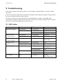
Troubleshooting . . . . . . . . . . . . . . . . . . . . . . . . . . . . . . . . . 66
LED Codes . . . . . . . . . . . . . . . . . . . . . . . . . . . . . . . . . . . . . . . . 66
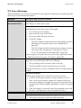
Error Messages. . . . . . . . . . . . . . . . . . . . . . . . . . . . . . . . . . . . . 67
The Red LED Glows Continuously (Ground Fault) . . . . . . . . . . 74
The Red LED is Flashing . . . . . . . . . . . . . . . . . . . . . . . . . . . . . . 75
9.4.1
Checking the Function of the Varistors (<Check Varistor>) . . . . . . . . . . . . . . 75
9.4.2
Replacing the String Fuses (<DC fuse>) . . . . . . . . . . . . . . . . . . . . . . . . . . . . 78
10
10.1
10.2
10.3
10.4
Decommissioning . . . . . . . . . . . . . . . . . . . . . . . . . . . . . . . . 80
Dismantling the Inverter. . . . . . . . . . . . . . . . . . . . . . . . . . . . . . . 80
Packing the Inverter. . . . . . . . . . . . . . . . . . . . . . . . . . . . . . . . . . 81
Storing the Inverter . . . . . . . . . . . . . . . . . . . . . . . . . . . . . . . . . . 81
Disposing of the Inverter . . . . . . . . . . . . . . . . . . . . . . . . . . . . . . 81
11
11.1
11.2
Technical Data . . . . . . . . . . . . . . . . . . . . . . . . . . . . . . . . . . 82
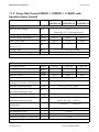
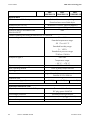
Sunny Mini Central 9000TL / 10000TL / 11000TL . . . . . . . . 82
Sunny Mini Central 9000TL / 10000TL / 11000TL
with Reactive Power Control . . . . . . . . . . . . . . . . . . . . . . . . . . . 85
12
Accessories . . . . . . . . . . . . . . . . . . . . . . . . . . . . . . . . . . . . . 88
13
Contact . . . . . . . . . . . . . . . . . . . . . . . . . . . . . . . . . . . . . . . . 90
Installation Guide
SMC9-11TLRP-IEN100640
5
Table of Contents
6
SMC9-11TLRP-IEN100640
SMA Solar Technology AG
Installation Guide
SMA Solar Technology AG
Notes on this Manual
1 Notes on this Manual
1.1 Validity
This installation guide describes the assembly, installation, commissioning and maintenance of the
following SMA inverters:
• Sunny Mini Central 9000TL (SMC 9000TL-10)
• Sunny Mini Central 10000TL (SMC 10000TL-10)
• Sunny Mini Central 11000TL (SMC 11000TL-10)
• Sunny Mini Central 9000TL with Reactive Power Control (SMC 9000TLRP-10)
• Sunny Mini Central 10000TL with Reactive Power Control (SMC 10000TLRP-10)
• Sunny Mini Central 11000TL with Reactive Power Control (SMC 11000TLRP-10)
Store this manual where it can be accessed at all times.
1.2 Target Group
This guide is for qualified electrical technicians. The tasks described in this manual may be performed
by qualified electrical technicians only.
1.3 Additional Information
You will find further information on special topics such as designing a line circuit breaker or the
description of the operating parameters in the download area at www.SMA.de/en.
Refer to the user manual for detailed information on operating the inverter.
Installation Guide
SMC9-11TLRP-IEN100640
7
Notes on this Manual
SMA Solar Technology AG
1.4 Symbols Used
The following types of safety instructions and general information appear in this document as
described below:
DANGER!
DANGER indicates a hazardous situation which, if not avoided, will result in death or
serious injury.
WARNING!
WARNING indicates a hazardous situation which, if not avoided, could result in death or
serious injury.
CAUTION!
CAUTION indicates a hazardous situation which, if not avoided, could result in minor or
moderate injury.
NOTICE!
NOTICE indicates a situation that can result in property damage if not avoided.
Information
Information provides tips that are valuable for the optimal installation and operation of
your product.
☑
8
This symbol indicates the result of an action.
SMC9-11TLRP-IEN100640
Installation Guide
SMA Solar Technology AG
Safety
2 Safety
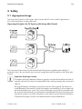
2.1 Appropriate Usage
The Sunny Mini Central is a PV inverter, which converts the DC current of the PV generator to
AC current and feeds it into the public grid.
Operating Principle of a PV System with Sunny Mini Central
The Sunny Mini Central may only be operated with PV generators (modules and cabling) of
protection class II. Do not connect any sources of energy other than PV modules to the Sunny Mini
Central.
Capacitive Discharge Currents
PV modules with large capacities relative to ground, such as thin-film modules with cells on
a metallic substrate, are only to be implemented if their coupling capacity does not exceed
1400 nF.
During grid feeding, a discharge current flows from the cells to ground. The amount of
current depends on the manner in which the modules are installed (e.g. foil on metal roof)
and on the weather (rain, snow). This "normal" discharge current may not exceed 50 mA
due to the fact that the inverter would otherwise automatically disconnect from the grid as
a protective measure. For further information on this subject, see the technical information
"Capacitive Discharge Currents" in the download area at www.SMA.de/en.
Installation Guide
SMC9-11TLRP-IEN100640
9
Safety
SMA Solar Technology AG
When designing the PV system, ensure that the values comply with the permitted operating range of
all components at all times. The free design program "Sunny Design" (www.SMA.de/en/
SunnyDesign) will assist you. The manufacturer of the PV modules must have approved the modules
for use with this Sunny Mini Central. You must also ensure that all measures recommended by the
module manufacturer for long-term maintenance of the module properties are taken (see also
Technical Information "Module Technology", in the download area of www.SMA.de/en).
Do not use the Sunny Mini Central for purposes other than those described here. Alternative uses,
modifications to the Sunny Mini Central or the installation of components not expressly recommended
or sold by SMA Solar Technology AG void the warranty claims and operation permission.
Certified Countries
The Sunny Mini Central 9000TL / 10000TL / 11000TL (with according configuration) fulfill the
requirements specified in the following standards and directives (dated: February/2010):
• VDE 0126-1-1 (02.2006)
• DK 5940 Ed. 2.2 (02.2006) (only for SMC 9000TL-10/IT / 10000TL-10/IT / 110000TL-10/IT)
• RD 1663/2000 (2000) a)
• PPC (06.2006) (only for SMC 9000TL-10 / 10000TL-10 / 11000TL-10)
• PPDS
• C10/C11 (08.2003) b)
• AS4777 (2005)
• IEC-utility Meeting 216
• RD 1663/661 (only for SMC 9000TLRP-10 / 10000TLRP-10 / 11000TLRP-10)
• MEA (on request)
• PEA (on request)
• Kepco guide (02.2006) (on request)
a) In the event of restrictions in certain regions, contact the SMA Serviceline.
b) Only possible when the phase voltage is 220 V.
SMA Solar Technology AG can preset special grid parameters for other countries / installation
locations according to customer request, after evaluation by SMA Solar Technology AG. You can
later make modifications yourself by changing software parameters with respective communication
products (e.g. Sunny Data Control or Sunny Explorer) (see section 5.8 ”Setting the Grid and Country
Parameters” (page 48)). To change grid-relevant parameters, you need a personal access code - the
so-called SMA Grid Guard Code. The application form for the personal access code is located in the
download area at www.SMA.de/en, in the "Data sheet" category for each inverter.
10
SMC9-11TLRP-IEN100640
Installation Guide
SMA Solar Technology AG
Safety
2.2 Safety Instructions
DANGER!
Danger to life due to high voltages in the inverter!
• All work on the inverter must be carried out by qualified personnel only.
• The appliance is not to be used by children or persons with reduced physical, sensory
or mental capabilities, or lack of experience and knowledge, unless they have been
given supervision or instruction.
• Children should be supervised to ensure that they do not play with the appliance.
DANGER!
Danger of burn injuries due to hot enclosure parts!
• Do not touch enclosure during operation.
• Only touch the lid during operation.
NOTICE!
Dust and water in the inverter can damage the device!
Once the Electronic Solar Switch has been pulled out, the inverter only provides protection
rating IP21. The inverter is then no longer protected against water and foreign objects. In
order to keep the protection rating IP65 during temporary decommissioning, proceed as
follows:
• Unlock and disconnect all DC connectors.
• Open all DC connectors and remove the wires.
• Close all DC inputs with the corresponding DC connectors and the supplied blank
plug.
• Securely attach the Electronic Solar Switch again.
Grounding the PV Generator
Comply with the local requirements for grounding the modules and the PV generator. SMA
Solar Technology AG recommends connecting the generator frame and other electricityconducting surfaces such that there is continuous conduction and to connect them to the
ground in order to reach maximum protection for property and persons.
Installation Guide
SMC9-11TLRP-IEN100640
11
Safety
SMA Solar Technology AG
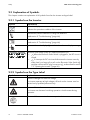
2.3 Explanation of Symbols
This chapter contains an explanation of all symbols found on the inverter and type label.
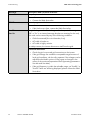
2.3.1 Symbols on the Inverter
Symbol
Explanation
Operation display.
Indicates the operation condition of the inverter.
Ground fault, varistor defective or string fuse defective
Read section 9 ”Troubleshooting” (page 66).
Disturbance or fault
Read section 9 ”Troubleshooting” (page 66).
Tap to switch on the display light and switch to the next display message.
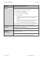
Electronic Solar Switch (ESS) DC load disconnection unit
•
When the Electronic Solar Switch is plugged in, the DC circuit is
closed.
•
To interrupt the DC circuit and disconnect the inverter securely
under load, you have to first pull out the Electronic Solar Switch
and then remove all DC plug connectors , as described in section
7.2 ”Opening the Inverter” (page 56).
2.3.2 Symbols on the Type Label
Symbol
Explanation
Beware of dangerous electrical voltage.
The inverter operates at high voltages. All work on the inverter must be
carried out by qualified personnel only.
Beware of hot surface.
The inverter can become hot during operation. Avoid contact during
operation.
Observe all documentation that accompanies the inverter.
12
SMC9-11TLRP-IEN100640
Installation Guide
SMA Solar Technology AG
Symbol
Safety
Explanation
The inverter must not be disposed of with the household waste. For more
information on disposal, see section 10.4 ”Disposing of the Inverter”
(page 81).
CE mark.
The inverter complies with the requirements of the applicable EC guidelines.
The inverter is transformerless.
Direct Current (DC)
Alternating current (AC)
Protection rating IP65.
The inverter is protected against penetration by dust particles and water
jets from any angle.
RAL quality mark for solar products.
The inverter complies with the requirements of the German Institute for
Quality Assurance and Labeling.
Installation Guide
SMC9-11TLRP-IEN100640
13
Unpacking
SMA Solar Technology AG
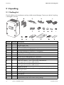
3 Unpacking
3.1 Packing List
Check the delivery for completeness and any visible external damage. Contact your dealer if anything
is damaged or missing.
Object
A
B
C
D
E
F
G
H
I
K
Number
1
1
1
1
10
10
1
1
1
2
L
2
C
N
1
2
O
P
Q
R
1
1
1
1
14
Description
Sunny Mini Central
Air grills (right / left)
Wall mounting bracket
Electronic Solar Switch (ESS) DC load disconnection unit
DC plug connectors (5 x positive / 5 x negative)
Blank plugs for DC plug connectors
Cable screw connection for AC connection
Counter nut for cable gland at AC connection
Clamping clip for additional grounding
Tooth lock washers: 1 x for cover screws (replacement),
1 x for ground connection cable terminal
Cylinder head screws (M6x16): 1 x for lid (replacement),
1 x for ground connection cable terminal
Jumper for fan test
Cylinder head screws (M6 x 8) for securing the Sunny Mini Central to the wall
mounting bracket
Installation guide
User manual
Set of documents with explanations and certificates
Supplementary sheet with inverter factory settings
SMC9-11TLRP-IEN100640
Installation Guide
SMA Solar Technology AG
Unpacking
3.2 Identifying the Inverter
You can identify the inverter by the type plate. The type label is on the right side of the enclosure.
The serial number (Serial No.) and the type (Type / Model) of the inverter, as well as device-specific
characteristics, are specified on the type label.
Installation Guide
SMC9-11TLRP-IEN100640
15
Installing the Device
SMA Solar Technology AG
4 Installing the Device
4.1 Safety
DANGER!
Danger to life due to fire or explosion!
Despite careful construction, electrical devices can cause fires.
• Do not mount the inverter on flammable construction materials.
• Do not mount the inverter in areas where highly flammable materials are stored.
• Do not mount the inverter in areas with a risk of explosion.
CAUTION!
Danger of burn injuries due to hot enclosure parts!
• Mount the inverter in such a way that it cannot be touched inadvertently.
CAUTION!
Risk of injury due to the heavy weight of the inverter!
• Take the inverter's weight of approx. 35 kg into account for mounting.
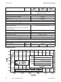
4.2 Selecting the Mounting Location
Consider the following requirements when selecting where to install:
• The installation method and mounting location must be suitable for the inverter's weight and
dimensions (see section 11 ”Technical Data” (page 82)).
• Mount on a solid surface.
• The mounting location must at all times be clear and have safe access without the use of
additional aids such as scaffolding or lifting platforms. Any possible service actions are
otherwise limited.
16
SMC9-11TLRP-IEN100640
Installation Guide
SMA Solar Technology AG
Installing the Device
• Vertical installation or tilted backwards by max. 15°.
• The connection area must point downwards.
• Never install the device with a forward tilt.
• Do not install horizontally.
• Install at eye level to allow operating status to be read at all times.
• The ambient temperature should be below 40 °C to ensure optimal operation.
• Do not expose the inverter to direct sunlight to avoid a power reduction due to excessive
heating.
• In living areas, do not mount the unit on plasterboard walls or similar in order to avoid audible
vibrations. The inverter can make noises when in use which may be perceived as a nuisance in
a living area.
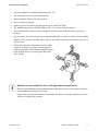
• Observe the minimum clearances to walls, other
inverters, or objects as shown in the diagram in
order to guarantee sufficient heat dissipation and to
have enough space for removing the Electronic
Solar Switch.
Multiple inverters installed in areas with high ambient temperatures
There must be sufficient clearance between the individual inverters to ensure the cooling air
from the adjacent inverter flows freely.
If necessary, increase the clearances and make sure there is enough ventilation to ensure
sufficient cooling of the inverters.
Installation Guide
SMC9-11TLRP-IEN100640
17
Installing the Device
SMA Solar Technology AG
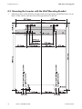
4.3 Mounting the Inverter with the Wall Mounting Bracket
1. Mark the position of the drill holes using the wall mounting bracket and drill the holes. Use at
least 2 of the 6 holes, with one hole on the right and one on the left.
18
SMC9-11TLRP-IEN100640
Installation Guide
SMA Solar Technology AG
Installing the Device
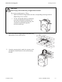
CAUTION!
Risk of injury due to the heavy weight of the inverter!
The inverter weights approx. 35 kg.
• Attach the wall mounting bracket with the corresponding mounting material
(depending on the surface).
• Use the side handles (above and below)
or a steel rod (maximum diameter of
30 mm) for transport and mounting. The
rod must be pushed through the
enclosure openings.
2. Secure the wall mounting bracket to the wall using
appropriate screws and washers.
3. Using the mounting hole, attach the inverter to the
rear panel of the enclosure in the wall mounting
bracket.
Installation Guide
SMC9-11TLRP-IEN100640
19
Installing the Device
SMA Solar Technology AG
4. Screw the inverter to the wall mounting bracket on
both sides using the screws (M6x8) provided.
Only tighten the screws hand-tight.
5. Check to ensure the inverter is firmly fastened.
6. Close the recessed grips with the fan grills
provided. The air grills are marked "rechts/right"
and "links/left" on the interior for proper
assignment.
The air grills prevent dirt and insects from entering
the device and, if necessary, can be reordered from
SMA Solar Technology AG (see section
12 ”Accessories” (page 88)).
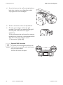
Optional Theft Protection
To protect the inverter against theft, the rear
panel can be secured to the wall at the bottom
using 2 single-use bolts.
The other two holes are spares.
20
SMC9-11TLRP-IEN100640
Installation Guide
SMA Solar Technology AG
Electrical Connection
5 Electrical Connection
NOTICE!
Electrostatic discharges can damage the inverter!
Internal components of the inverter can be irreparably damaged by static discharge.
• Ground yourself before touching a component.
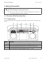
5.1 Overview of the Connection Area
5.1.1 Exterior View
The following figure shows the assignment of the individual connection areas on the bottom of the
inverter.
Object
A
B
C
D
E
Description
DC connector for connecting the PV strings
Socket for connecting the Electronic Solar Switch (ESS) DC load disconnection unit
Enclosure openings for optional communication via RS485 or radio (PG16)
Connection of the SMA Power Balancer
Enclosure opening for connecting to grid (AC) (18 mm … 32 mm)
Installation Guide
SMC9-11TLRP-IEN100640
21
Electrical Connection
SMA Solar Technology AG
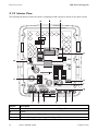
5.1.2 Interior View
The following illustration shows the various components and connection areas of the open inverter.
Object
A
B
C
D
Description
Connection area and sockets for communication (Page 48)
Display
Jumper slot for fan test (Page 62)
LEDs for displaying the operating modes (Page 56)
22
SMC9-11TLRP-IEN100640
Installation Guide
SMA Solar Technology AG
Object
E
F
G
H
I
K
L
M
N
O
Electrical Connection
Description
Connection terminals for mains cable (AC) (Page 24)
Male connector for grounding the cable shield for communication (Page 48)
Screwing device for shield clamp for communication cable (Page 48)
Enclosure opening for mains cable (AC) (Page 24)
Connection socket for SMA Power Balancer (Page 39)
Enclosure openings for communication (Page 48)
DC connector (Page 32)
Connection socket for Electronic Solar Switch (ESS) DC load disconnection unit
(Page 32)
Slot for string fuses (Page 30)
Varistors (Page 75)
Installation Guide
SMC9-11TLRP-IEN100640
23
Electrical Connection
SMA Solar Technology AG
5.2 Connection to the Public Grid (AC)
5.2.1 Conditions for the AC Connection
Connection requirements of the utility operator
Always observe the connection requirements of your utility operator!
Dimensioning of the Cables
The conductor cross-section should be dimensioned in a way that output losses do not exceed 1 % at
nominal power. Use "Sunny Design" (www.SMA.de/en) for this.
The maximum cable lengths relative to the conductor cross-section are shown in the following table.
Conductor crosssection
SMC 9000TL-10 /
16.0 mm²
25,0 mm² a)
SMC 9000TLRP-10
27 m
43 m
a)
Maximum wire length
SMC 10000TL-10 / SMC 11000TL-10 /
SMC 10000TLRP-10
24 m
38 m
SMC 11000TLRP-10
22 m
35 m
Only use flexible cables!
Cut line losses in half
If three inverters with symmetrical feeding are combined to form a three-phase system, the
neutral conductor is not subjected to any load, and the line losses are halved. Thus, the
maximum possible cable length is doubled.
The conductor cross-sectional area required in individual cases depends on the following factors:
• ambient temperature,
• routing method,
• UV resistance.
Cable Requirements
Position
A
B
C
24
Description
External diameter
Conductor cross-section
Strip insulation
SMC9-11TLRP-IEN100640
Value
18 mm … 32 mm
Max. 25 mm²
Approx. 18 mm
Installation Guide
SMA Solar Technology AG
Electrical Connection
Load Disconnection Unit
You must install a separate line circuit breaker for each inverter in order to ensure that the inverter
can be securely disconnected under load. The maximal permissible rating is located in section
11 ”Technical Data” (page 82).
Detailed information and examples for the rating of a line circuit breaker can be found in the Technical
Information "Line Circuit Breaker" in the SMA Solar Technology AG download area at
www.SMA.de/en.
DANGER!
Danger to life due to fire!
When more than one inverter are connected in parallel to the same line circuit breaker, the
protective function of the line circuit breaker is no longer guaranteed. It can result in a cable
fire or the destruction of the inverter.
• Never connect several inverters to the same line circuit breaker.
• Comply with the maximum permissible fuse protection of the inverter when selecting
the line circuit breaker.
DANGER!
Danger to life due to fire!
When a generator (inverter) and a consumer are connected to the same line circuit
breaker, the protective function of the line circuit breaker is no longer guaranteed. The
current from the inverter and the grid can accumulate to overcurrent which is not detected
by the line circuit breaker.
• Never connect consumers between the
inverter and the line circuit breaker
without protection.
• Always protect consumers separately.
NOTICE!
Damage to the inverter by using screw type fuse elements as load disconnection
unit!
A screw type fuse element, e.g. D system (Diazed) or D0 system (Neozed) is not a load
disconnection unit, and thus may not be used as a load disconnection unit. A screw type
fuse element is only used as cable protection.
When disconnecting under load using a screw type fuse element, the inverter can be
damaged.
• Use only a load disconnecting switch or a line circuit breaker as load disconnecting
unit.
Installation Guide
SMC9-11TLRP-IEN100640
25
Electrical Connection
SMA Solar Technology AG
5.2.2 Connecting the Inverter to the Public Grid (AC)
1. Check the grid voltage and compare with "VAC nom" on the type label.
The exact operating range of the inverter is specified in the operating parameters. The
corresponding document is located in the download area at www.SMA.de/en, in the
"Technical Description" category of the respective inverter.
2. Disconnect the line circuit breaker and secure against re-connection.
3. Loosen all cover screws and remove the cover.
4. Remove tape on the AC enclosure opening
(see "E" on Page 21).
5. Insert the AC screw clamp into the enclosure
opening from the outside and tighten it with the
counter nut from the inside.
6. Pull the cable through.
7. Connect L, N and the protective conductor (PE) to
the terminal blocks using a screwdriver in
accordance with the label.
To do this, the PE wire must be 5 mm longer than the
L and N wires.
L and N must not be swapped.
8. Securely close the clamp at the enclosure opening.
26
SMC9-11TLRP-IEN100640
Installation Guide
SMA Solar Technology AG
Electrical Connection
9. Secure the lid with all screws and the
corresponding tooth lock washers.
Tighten the screws with 6 Nm torque in the order
shown on the right hand side. The toothing of the
tooth lock washers must face toward the lid.
The inverter packing list includes another spare
screw and tooth lock washer.
DANGER!
Danger to life due to live lid!
The grounding of the enclosure lid is ensured by the tooth lock washers.
• Fasten the tooth lock washers for all 6 screws with the toothing facing toward the lid.
DANGER!
Danger to life due to high voltages in the inverter!
• Do not switch on the line circuit breaker until the inverter is securely closed and also
the PV generator has been connected.
☑ The inverter is now connected to the public grid (AC).
Installation Guide
SMC9-11TLRP-IEN100640
27
Electrical Connection
SMA Solar Technology AG
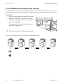
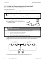
5.2.3 Additional Grounding of the Housing
If a second protective conductor connection is required in the country of installation, you can also
ground the inverter using a second protective conductor on the connection terminal on the enclosure.
Procedure
1. Insert the stripped grounding cable (D) under the
clamping clip (C) (max. cross-section 16 mm²).
2. Screw the clamping clip tight with screw (A) and
tooth lock washer (B).
The toothing of the tooth lock washer must face
toward the clamping clip.
☑ The inverter's enclosure is additionally grounded.
You can ground multiple inverters as shown in the diagram below:
28
SMC9-11TLRP-IEN100640
Installation Guide
SMA Solar Technology AG
Electrical Connection
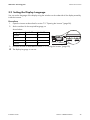
5.3 Setting the Display Language
You can set the language of the display using the switches on the underside of the display assembly
inside the inverter.
Procedure
1. Open the inverter as described in section 7.2 ”Opening the Inverter” (page 56).
2. Set the switches for the required language, as
shown below.
Language
German
English
French
Spanish
Switch S2
B
B
A
A
Switch S1
B
A
B
A
3. Close the inverter as described in section 7.3 ”Closing the Inverter” (page 59).
☑ The display language is now set.
Installation Guide
SMC9-11TLRP-IEN100640
29
Electrical Connection
SMA Solar Technology AG
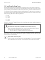
5.4 Installing the String Fuses
The Sunny Mini Central can be equipped with special string fuses to protect the PV modules from
reverse currents. Whether string fuses must be used depends on the PV modules used and the number
of strings directly connected to the Sunny Mini Central. If necessary, consult the module manufacturer.
The Sunny Mini Central is equipped with factory-installed jumpers. The inputs are thus unprotected. If
necessary, the jumpers can be replaced with special string fuses (thermal fuses). At the moment, SMA
Solar Technology AG offers the following add-on kits:
• 5x8A
• 5 x 10 A
• 5 x 12 A
• 5 x 16 A
• 5 x 20 A
Section 12 ”Accessories” (page 88) contains a list of the SMA order numbers. Additional types are
available upon request.
NOTICE!
The Sunny Mini Central can be damaged if the string fuses burn out!
When using commercially available fuses, it cannot be ensured that they will function
correctly and in case of a fault, the string fuses may burn out.
• Only use add-on kits provided by SMA Solar Technology AG.
If installed, the string fuses in the Sunny Mini Central will be monitored automatically. In the case of a
burnt-out fuse, the error message "Check DC fuse" appears in the display. However, the Sunny Mini
Central continues to feed electricity.
Equip all slots with a string fuse
To ensure that the fuse monitoring function is working properly, all 5 slots must be equipped
with the appropriate fuses at all times. This also applies if fewer strings are connected.
30
SMC9-11TLRP-IEN100640
Installation Guide
SMA Solar Technology AG
Electrical Connection
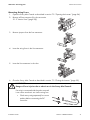
Mounting String Fuses
1. Open the Sunny Mini Central as described in section 7.2 ”Opening the Inverter” (page 56).
2. Remove all fuse extractors (for slot see section
5.1.2 ”Interior View” (page 22)).
3. Remove jumpers from the fuse extractors.
4. Insert the string fuses in the fuse extractors.
5. Insert the fuse extractors in the slots.
6. Close the Sunny Mini Central as described in section 7.3 ”Closing the Inverter” (page 59).
WARNING!
Danger of burn injuries due to electric arc in the Sunny Mini Central!
If a string is connected with the poles reversed
it can cause an electric arc via the string fuse.
• Check every string separately for correct
polarity before connecting the DC
connector.
Installation Guide
SMC9-11TLRP-IEN100640
31
Electrical Connection
SMA Solar Technology AG
5.5 Connection of the PV Generator (DC)
5.5.1 Conditions for the DC Connection
Use of Adaptors
Adaptors (branch connectors) are not to be visible or freely accessible in the immediate
surroundings of the inverter.
• The DC current flow may not be interrupted via adaptors.
• Observe the procedure for disconnecting the inverter as described in section
7.2 ”Opening the Inverter” (page 56).
• Requirements for the PV modules of the connected strings:
– Same type
– Same number
– Identical alignment
– Identical tilt
• The connecting cables from the PV modules must be fitted with plug connectors. You will find
the necessary DC plug connector for DC connection in the delivery.
• The following limit values at the DC input of the inverter may not be exceeded:
Inverter
SMC 9000TL-10 / SMC 9000TLRP-10
SMC 10000TL-10 / SMC 10000TLRP-10
SMC 11000TL-10 / SMC 11000TLRP-10
Maximum input
voltage
700 V (DC)
700 V (DC)
700 V (DC)
Maximum input
current
28.0 A (DC)
31.0 A (DC)
34.0 A (DC)
DANGER!
Risk of lethal electric shock or fire!
The maximum possible input current per string is limited by the plug connectors used. If the
plug connector is overloaded, an electric arc may occur and there is a fire risk.
• Ensure that the input current for each string does not exceed the maximum flow
current of the plug connectors used.
The residual current breaker
The inverter is equipped with an integrated universal current sensitive residual-current
monitoring unit. The inverter can automatically differ between real fault currents and
"normal" capacitive leakage currents.
If an external RCD or residual current breaker is strictly required, you must use a switch that
triggers at a failure current of 100 mA or higher.
32
SMC9-11TLRP-IEN100640
Installation Guide
SMA Solar Technology AG
Electrical Connection
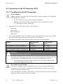
5.5.2 Assembling the DC Plug Connector
In order to connect to the inverter, all connecting cables of the PV modules must be equipped with the
DC plug connectors provided.
To assemble the DC plug connectors, proceed as detailed below. Ensure the plug connectors have
the correct polarity. The DC plug connectors are marked with "+" and "–".
Cable requirements:
• Use a PV1-F cable.
Procedure
1. Insert the stripped cable into the plug connector as
far as it will go.
2. Press the clamping bracket down until it audibly
snaps into place.
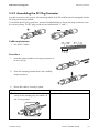
3. Ensure the cable is correctly in place.
Result
☑ If the conductors are visible in the hollow
cavity of the clamping clip, the cable is in
the correct position.
Installation Guide
Action
• Proceed to step 4.
SMC9-11TLRP-IEN100640
33
Electrical Connection
SMA Solar Technology AG
Result
Action
☑ If the conductor is not visible in the hollow • Loosen the clamping clip with the help of a
cavity of the clamp, the cable is not in the
screwdriver.
correct position.
• Remove cable and start again from step 1.
4. Push the threaded joint to the thread and screw into place.
☑ The DC plug connectors are now assembled and can be connected to the inverters, as
described in section 5.5.4 ”Connecting the PV Generator (DC)” (page 36).
34
SMC9-11TLRP-IEN100640
Installation Guide
SMA Solar Technology AG
Electrical Connection
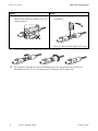
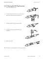
5.5.3 Opening the DC Plug Connector
1. Screw the threaded joint off.
2. To release the plug connector, slot a screw driver
into the side catch mechanism and lever out.
3. Carefully pull the DC plug connector apart.
4. Loosen the clamping clip with the help of a
screwdriver.
5. Remove the cable.
☑ The cable is now removed from the DC plug connector.
Installation Guide
SMC9-11TLRP-IEN100640
35
Electrical Connection
SMA Solar Technology AG
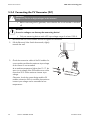
5.5.4 Connecting the PV Generator (DC)
DANGER!
Danger to life due to high voltages in the inverter!
• Before connecting the PV generator, ensure that the line circuit breaker is switched
off.
NOTICE!
Excessive voltages can destroy the measuring device!
• Only use measuring devices with a DC input voltage range of at least 1000 V.
1. Disconnect the line circuit breaker and secure against re-connection.
2. Pull the Electronic Solar Switch downwards, slightly
towards the wall.
3. Check the connection cables of the PV modules for
correct polarity and that the maximum input voltage
of the inverter is not exceeded.
At an ambient temperature higher than 10 °C, the
open circuit voltage of the PV modules must not be
more than 90 % of the maximum inverter input
voltage.
Otherwise, check the system design and the PV
module connection. If this is not done, the maximum
inverter input voltage can be exceeded at low
temperatures.
36
SMC9-11TLRP-IEN100640
Installation Guide
SMA Solar Technology AG
Electrical Connection
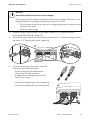
NOTICE!
Destruction of the inverter due to overvoltage!
If the voltage of the PV modules exceeds the maximum input voltage of the inverter, it can
be destroyed by the overvoltage. All warranty claims become void.
• Do not connect strings with an open circuit voltage greater than the maximum input
voltage of the inverter.
• Check the system design.
4. Check the strings for ground faults, as described in section 9.3 ”The Red LED Glows
Continuously (Ground Fault)” (page 74).
5. Check the DC plug connector for correct polarity and connect it. To release the plug connectors
see section 7.2 ”Opening the Inverter” (page 56).
6. To create the sealing on the inverter, all the DC
inputs have to be closed as follows:
– Insert the blank plugs provided into the
unnecessary DC plug connectors.
Do not insert the sealing plugs into the DC
inputs on the inverter.
– Insert the DC plug connectors with sealing plugs
into the corresponding DC inputs on the inverter.
Installation Guide
SMC9-11TLRP-IEN100640
37
Electrical Connection
SMA Solar Technology AG
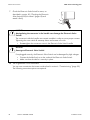
7. Check the Electronic Solar Switch for wear, as
described in section 8.2 ”Checking the Electronic
Solar Switch (ESS) for Wear” (page 65) and
attach it firmly.
NOTICE!
Manipulating the connector in the handle can damage the Electronic Solar
Switch!
The connector inside the handle must remain movable in order to ensure proper contact.
Tightening the screw voids all warranty claims and creates a fire risk.
• Do not tighten the connector screw in the Electronic Solar Switch handle.
NOTICE!
Damage to Electronic Solar Switch!
If not plugged correctly, the Electronic Solar Switch can be damaged by high voltages.
• Connect the holder firmly on to the socket of the Electronic Solar Switch.
• Make sure that the device is securely in place.
☑ The PV generator is now connected.
You can now commission the inverter as described in section 6 ”Commissioning” (page 55).
The following connection options are optional.
38
SMC9-11TLRP-IEN100640
Installation Guide
SMA Solar Technology AG
Electrical Connection
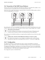
5.6 Connection of the SMA Power Balancer
The Sunny Mini Central is equipped with the SMA Power Balancer as standard. This enables a circuit
connection of three 3 Sunny Mini Central to a three-phase feed-in system.
Each of the 3 Sunny Mini Central devices in a group must be connected to a different phase conductor
of the low-voltage grid (L1, L2 and L3)!
By activating this circuit, you can stipulate how the other two Sunny Mini Central devices are to react
if there is a device fault with the third Sunny Mini Central or there is a grid voltage fault in its phase.
Three-phase grid connection
For further information on this subject, see the technical information "Three-phase grid
connection with Sunny Mini Central" in the download area at www.SMA.de/en.
The connections for the SMA Power Balancer are galvanically isolated from the rest of the Sunny Mini
Central circuit.
Cable for the connection of the SMA Power Balancer connector system
The cable for the connection is not provided as standard, but rather must be ordered
separately from SMA Solar Technology AG (see section 12 ”Accessories” (page 88)).
5.6.1 Configuration
The SMA Power Balancer is deactivated at the factory using the "PowerBalancer" parameter
(parameter setting = off) and can only be activated and configured using a communication device.
To change the "PowerBalancer" parameter, you need a personal access code - the so-called SMA
Grid Guard Code. The application form for the personal access code is located in the download area
at www.SMA.de/en, in the "Data sheet" category for each inverter.
The configuration options are detailed below.
Installation Guide
SMC9-11TLRP-IEN100640
39
Electrical Connection
SMA Solar Technology AG
Configuration Options
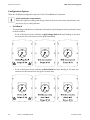
There are 4 different configuration options for the "PowerBalancer" parameter.
Local connection requirements
Select the respective setting and always observe the local connection requirements and
provisions of your utility operator.
• FaultGuard
This operating mode allows to implement a three-phase grid voltage monitoring that also reacts
to device failures.
– If one of the three inverters indicates a grid voltage fault and stops feeding in, the other
two inverters also disconnect from the grid immediately.
– If one of the three inverters indicates a device fault and stops feeding in, the other two
inverters also disconnect from the grid 5 minutes later.
40
SMC9-11TLRP-IEN100640
Installation Guide
SMA Solar Technology AG
Electrical Connection
• PhaseGuard
This operating mode allows to implement a three-phase grid voltage monitoring.
– If one of the three inverters indicates a grid voltage fault and stops feeding in, the other
two inverters also disconnect from the grid automatically.
– If one of the three inverters indicates a device fault and stops feeding in, the other two
inverters are not affected and continue to feed in at full power.
Installation Guide
SMC9-11TLRP-IEN100640
41
Electrical Connection
SMA Solar Technology AG
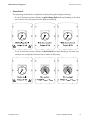
• Off
The SMA Power Balancer is deactivated (factory setting).
– In the event of a device fault or grid voltage fault at an inverter, only this inverter is
disconnected from the grid and the other two inverters continue to run at an undiminished
power level.
42
SMC9-11TLRP-IEN100640
Installation Guide
SMA Solar Technology AG
Electrical Connection
• PowerGuard
This setting can be selected, if the entire PV plant consists of three 3 Sunny Mini Central inverters
only and in case of a failure the unbalanced load shall be limited to 5 kVA over a 10-minute
average.
Unbalanced load limitation in case of SMC 9000TL-10/IT / 10000TL-10/IT /
11000TL-10/IT (applies exclusively to Italy)
In the case of the Sunny Mini Central 9000TL-IT /10000TL-IT / 11000TL-IT, the
unbalanced load is limited to 6 kVA.
– If one of the three inverters indicates a grid voltage fault or device fault and stops feeding
in, the other two inverters automatically limit their power to 5 kVA over a 10 minute average.
Installation Guide
SMC9-11TLRP-IEN100640
43
Electrical Connection
SMA Solar Technology AG
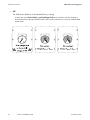
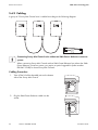
5.6.2 Cabling
A group of 3 Sunny Mini Central units is cabled according to the following diagram:
Connecting Sunny Mini Central units without an SMA Power Balancer connector
system
When connecting Sunny Mini Centrals with an SMA Power Balancer but without the SMA
Power Balancer connector system, you require a special upgrade kit (order number:
PBL-SMC-10-NR) for these Sunny Mini Centrals.
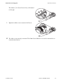
Cabling Procedure
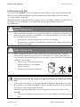
1. Twist off the lid of the threaded joint on the bottom
side of the Sunny Mini Central.
2. Plug the SMA Power Balancer cable into the
socket.
44
SMC9-11TLRP-IEN100640
Installation Guide
SMA Solar Technology AG
Electrical Connection
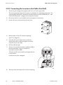
The markers (1 to 3) must form a line, as illustrated
on the right.
3. Tighten the cable screw connection half a turn.
☑ The cable is now securely connected. The SMA Power Balancer can now be activated via a
communication device.
Installation Guide
SMC9-11TLRP-IEN100640
45
Electrical Connection
SMA Solar Technology AG
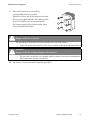
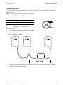
Extending the Cable
If you must bridge large spans between 2 Sunny Mini Centrals, you can extend the SMA Power
Balancer cable.
Use an "LiYCY" cable for this with the illustrated layout:
• Indoors: Li-2YCY 1 x 2 x 0.25 mm²
• Outdoors: Li-2YCYv 1 x 2 x 0.25 mm²
Object
A
B
C
Description
Flexible insulation
Shielding
Twisted pair (1 x 2 x 0.25 mm²)
Proceed as follows:
1. Cut the SMA Power Balancer cable in the middle.
2. Connect the wires and shield inside a junction box (outdoors) with an extension cable 1:1
(max. cable length 300 m).
3. Connect the SMA Power Balancer cable to the Sunny Mini Central as described in section
”Cabling Procedure” (page 44).
46
SMC9-11TLRP-IEN100640
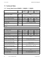
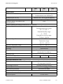
Installation Guide
SMA Solar Technology AG
Electrical Connection
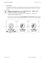
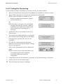
5.6.3 Testing the Functioning
To test whether the SMA Power Balancer operates correctly, proceed as follows.
1. Select the "PhaseGuard" setting of the "PowerBalancer" parameter for all three inverters.
2. Check whether all inverters in the group are feeding the grid normally.
☑ If the green LED lights up steadily or if the
display message pictured opposite appears,
proceed with point 3.
E-today
Mode
0Wh
MPP
or
☑ If all inverters in this group show the display
message pictured to the opposite: check the
installation of the SMA Power Balancer and
contact SMA Solar Technology AG, if
necessary.
Disturbance
PowerBalance
3. Switch off the line circuit breaker for one of the
three inverters.
• The inverter with a deactivated line circuit breaker
then indicates a grid voltage fault with the display
message shown opposite ("Bfr" and "Srr" are
irrelevant).
Disturbance
Vac-Bfr
• The other two inverters then also disconnect
themselves from the grid with the display message
shown to the opposite.
Disturbance
PowerBalance
Both inverters subsequently switch to "Balanced"
mode.
☑ If the inverters react as described above, the
functionality test has been completed
successfully. Otherwise, check the
configuration.
4. If applicable, reset the "PowerBalancer" parameter to the desired setting in all inverters.
5. Switch on the line circuit breaker again.
☑ The functionality test has been completed.
Installation Guide
SMC9-11TLRP-IEN100640
47
Electrical Connection
SMA Solar Technology AG
5.7 Communication
The inverter is equipped with a slot for communication interfaces in order to communicate with special
data acquisition devices (e.g. Sunny WebBox) or a PC with corresponding software (e.g. Sunny Data
Control or Sunny Explorer).
See the respective communication interface manual for a detailed wiring diagram and an installation
description for the interface.
Using the Power Reducer Box from SMA Solar Technology AG, it is possible to set a limit for the active
power for all inverters. Also, the reactive power specification can be controlled in Sunny Mini Central
units with Reactive Power Control. For detailed information on the Power Reducer Box, see its
technical description and the technical information on "Grid safety management" in the download
area under www.SMA.de/en.
5.8 Setting the Grid and Country Parameters
Changing Grid-Relevant and Country Parameters
To change grid-relevant parameters, you need a personal access code - the so-called SMA
Grid Guard Code. The application form for the personal access code is located in the
download area at www.SMA.de/en, in the "Data sheet" category for each inverter.
Ensure that you discuss the changes to these parameters with your utility operator.
A detailed description of the operating parameter for the inverter is available in the download area
at www.SMA.de/en in the category "Technical Description" of the respective inverter.
5.8.1 Setting the Installation Country
Using the "Default" parameter you can set the installation country and/or the grid connection
standard valid for the country via a communication device (e.g. Sunny WebBox) or a PC with
appropriate software (e.g. Sunny Data Control or Sunny Explorer). This, however, is only required if
the inverter was originally ordered for another country. You can see the standard to which the inverter
was set upon delivery from the type label and the supplementary document provided with the factory
settings.
48
SMC9-11TLRP-IEN100640
Installation Guide
SMA Solar Technology AG
Electrical Connection
5.8.2 Setting Off-Grid Operation
To operate the inverter in an off-grid system with Sunny Island, you must set the inverter via the
"Default" parameter to off-grid ("OFF-Grid") operation.
You have several possibilities to set the inverter to off-grid operation:
• Setting via Sunny WebBox
or
• Setting via Sunny Data Control or Sunny Explorer.
DANGER!
Danger to life due to high voltages in the event of outage of the public grid.
If you set the inverter to off-grid operation, it does not fulfill any country-specific standards
and regulations. Therefore, if there is an outage of the public grid, there is a danger of back
feed.
• Never operate the inverter directly on the public grid when set to off-grid operation.
5.8.3 Additional Country Parameter
Requirements for the setting
Set the installation country as described in section 5.8.1 ”Setting the Installation Country”
(page 48) before setting the country parameter described here.
The deactivation criteria (voltage, frequency) are specified via country parameters for all Sunny Mini
Central inverters.
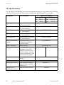
Type SMC 9000TLRP-10 / 100000TLRP-10 / 110000TLRP-10 Sunny Mini Centrals have an
additional default country parameter "MVtgDirective". This parameter expands the deactivation limits
of the inverter for voltage and frequency to a maximum / minimum. This country setting may only be
selected if the plant or inverter is operated with an external three-phase decoupling protection, which
disconnects the Sunny Mini Central from the grid automatically if non-permissible voltage and
frequency values occur. Device protection is still guaranteed.
DANGER!
Risk of lethal electric shock if external decoupling protection is missing!
If the country setting is "MVtgDirective", the Sunny Mini Central with Reactive Power
Control may only be operated with an external three-phase decoupling protection device
which complies with the country-specific requirements.
Without this external decoupling protection, the Sunny Mini Central does not disconnect
from the grid when the standard requirements are exceeded.
• Install external three-phase decoupling protection.
Installation Guide
SMC9-11TLRP-IEN100640
49
Electrical Connection
SMA Solar Technology AG
5.9 Reactive Power and Grid Management
Sunny Mini Central units 9000TL / 10000TL / 11000TL with Reactive Power Control are reactive
power-compatible inverters and can feed in reactive power by entering a shift factor (cos ϕ). These
inverters are also equipped with advanced grid management functions for output control, which can
be activated and configured in accordance with the requirements of the utility operator.
The configuration parameters are protected by the SMA Grid Guard Code password. However, they
can only be accessed at the installer level. To set all parameters you need a personal SMA Grid
Guard Code and the installer password. The application form for the SMA Grid Guard Code is
located in the download area at www.SMA.de/en, in the "Data sheet" category for each inverter.
The installer password can be obtained from the SMA Serviceline upon request. Confirm the changes
to these parameters with your utility operator.
With the procedures described below, you can select different settings in which additional
configuration parameters can be set.
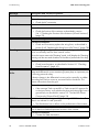
5.9.1 Setting the Displacement Power Factor cos ϕ
The "Q-VArMod" parameter allows you to select the reactive power process for the Sunny Mini
Centrals with Reactive Power Control. 3 settings can be selected.
The displacement power factor (cos ϕ) can be specified by setting a software parameter for the
corresponding device (Mode 1) or transmitted to multiple devices via the Sunny WebBox in
combination with the Power Reducer Box (Mode 2).
The factory setting for the displacement power factor is cos ϕ = 1 (Mode 1).
Procedures and Configuration Parameters
Default settings
In the table below, default settings are marked with *.
Procedure
Q-VArMod
Setting
PFCnst*
PFCtlCom
Description
Mode 1: Constant displacement power factor cos ϕ.
Mode 2: Displacement power factor is transferred by
communication via Power Reducer Box.
The process is deactivated.
Off
Configuration Options for "PFCnst"
Setting
PFCnst
Parameters
PF-PF
PF-PFExt
50
Description
Displacement power factor
specification cos ϕ (Mode 1).
Type of excitation of the
displacement power factor cos
ϕ (Mode 1).
SMC9-11TLRP-IEN100640
Value range
0.8 ... 1
Default
1
Underexcited, Underexcited
overexcited
Installation Guide
SMA Solar Technology AG
Electrical Connection
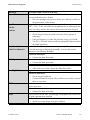
5.9.2 Frequency-dependent Active Power Limitation P(f)
Activating this function enables active power limitation P depending on the grid frequency fAC. The
process used complies with the Medium Voltage Regulation valid in Germany. However, the settings
can also be adjusted to the requirements of other countries or utility operators by means of software
parameters.
The "P-WCtlHzMod" parameter allows you to select the frequency-dependent active power limitation
P(f). 2 settings can be selected.
This process is deactivated on delivery.
Procedures and Configuration Parameters
Default settings
In the table below, default settings are marked with *.
Procedure
P-WCtlHzMod
Setting
Off*
On
Description
The process is deactivated.
The active power is throttled in accordance with the
characteristic curve.
Configuration Options for "On"
Setting
On
Parameters
P-HzStr
P-WGra
P-HzStop
Installation Guide
Description
Start frequency (nominal
frequency + setting) for active
power limitation.
Steepness of the active power
limitation (gradient).
Frequency (nominal frequency +
setting) for resetting the active
power limitation.
Value range
0 ... 5 Hz
Default
0.20 Hz
10 ... 100 %/Hz
40 %/Hz
0 ... 5 Hz
0.05 Hz
SMC9-11TLRP-IEN100640
51
Electrical Connection
SMA Solar Technology AG
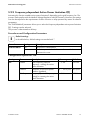
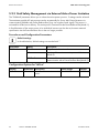
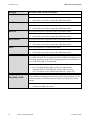
5.9.3 Grid Safety Management via External Active Power Limitation
The "P-WMod" parameter allows you to select the active power process. 3 settings can be selected.
The maximum possible AC active power can be set externally for Sunny Mini Central inverters via
communication (WebBox with Power Reducer Box) (e.g. via a ripple control signal). This process is
activated for all devices on delivery. The active power is restricted via the Power Reducer Box (Mode 1).
A fixed limitation of the active power of an individual inverter can also be set, however external
specification via the Power Reducer Box is then no longer possible.
Procedures and Configuration Parameters
Default settings
In the table below, default settings are marked with *.
Procedure
P-WMod
Setting
Off
WCnst
WCtlCom*
Description
The process is deactivated.
Limitation of the maximum active power of the inverter
(Mode 2).
Limitation of the maximum active power via
communication with a Power Reducer Box (Mode 1).
Configuration Options for "WCnst"
Setting
WCnst
52
Parameters Description
Value range
P-W
Limitation of the maximum active 0 ... 11110
power.
SMC9-11TLRP-IEN100640
Default
11000
Installation Guide
SMA Solar Technology AG
Electrical Connection
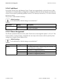
5.9.4 Soft Start
Sunny Mini Central units with Reactive Power Control are equipped with a soft start function. After
reactivation, for example after a voltage fault or frequency fault, the soft start function increases the
output of active power gradually (gradient function). The capacity increases by 10 % of the nominal
power per minute.
This process is deactivated on delivery.
Default settings
In the table below, default settings are marked with *.
Procedure
WGraReconEna
Setting
0*
1
Description
Soft start is deactivated.
Soft start is activated.
5.9.5 Phase Assignment
The "Phase" parameter allows the Sunny Mini Central units to be assigned to phase L1, L2 or L3. This
function allows a communication command to be sent only to the inverters with the specific phase
setting when using the Power Reducer Box.
Default settings
In the table below, default settings are marked with *.
Parameters
Phase
Setting
-----*
L1
L2
L3
Installation Guide
Description
This setting means that no active setting was selected. The
inverter reacts as in setting "L1".
The inverter is assigned to phase L1.
The inverter is assigned to phase L2.
The inverter is assigned to phase L3.
SMC9-11TLRP-IEN100640
53
Electrical Connection
SMA Solar Technology AG
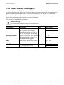
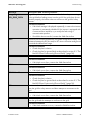
5.9.6 Limited Dynamic Grid Support
From firmware version 2.00/2.00, the Sunny Mini Central units with Reactive Power Control feature
the function for limited the dynamic grid support. Using this function, the inverter can begin feeding
again immediately following the end of a short-term interruption to the voltage. The inverter also
disconnects from the mains through the internal decoupling protection with the set country parameter
and/or through the external three-phase decoupling protection.
This function has 4 adjustable parameters.
Default settings
In the table below, default settings are marked with *.
Parameters
DGS-PWMVolNom
DGS-HystVolNom
VRef
VRefOfs
54
Description
Cut-off voltage in percent relative to
VRef + VRefOfs. When the AC
voltage drops below the value set
here, the inverter will stop feeding.
Hysteresis in percent. When the AC
voltage exceeds the value set, the
inverter starts feeding again.
Phase voltage at the output side of
the transformer.
Unit
%
Value range
40 ... 100
70*
%
0 ... 60
5*
V
Adjustable voltage offset
(e.g. through output losses).
V
215 ... 245
230*
–20 ... +20
0*
SMC9-11TLRP-IEN100640
Installation Guide
SMA Solar Technology AG
Commissioning
6 Commissioning
1. Check the following requirements before commissioning:
– The inverter is firmly fastened.
– Correct connection of the AC cable (grid)
– Full connection of the DC cables (PV strings)
– Unnecessary DC inputs are closed with the corresponding DC plug connectors and blank
plugs
– The enclosure lid is securely screwed in place
– Electronic Solar Switch is securely plugged
– The line circuit breaker is laid out correctly
2. Switch on the line circuit breaker.
☑ The green LED is glowing or blinking if there is
enough radiation: commissioning has been
successful.
or
☑ The red or yellow LED is glowing or blinking:
there is an error. Proceed to step 3.
A Green LED
B Red LED
C Yellow LED
In operation
Ground fault, varistor defective
or string fuse defective
Fault
3. Read section 9 ”Troubleshooting” (page 66) and if necessary eliminate the fault or disturbance.
Installation Guide
SMC9-11TLRP-IEN100640
55
Opening and Closing
SMA Solar Technology AG
7 Opening and Closing
7.1 Safety
DANGER!
Risk of lethal electric shock!
Observe the following before opening the inverter:
• Ensure the AC side is not live.
• Ensure the DC side is not live.
NOTICE!
Electrostatic discharges can damage the inverter.
Internal components of the inverter can be irreparably damaged by electrostatic
discharge.
• Ground yourself before touching a component.
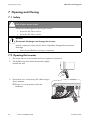
7.2 Opening the Inverter
1. Disconnect the line circuit breaker and secure against re-connection.
2. Pull the Electronic Solar Switch downwards, slightly
towards the wall.
3. Ensure there is no current at any DC cables using a
clip-on ammeter.
☑ If there is a current present, check the
installation.
56
SMC9-11TLRP-IEN100640
Installation Guide
SMA Solar Technology AG
Opening and Closing
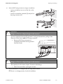
4. Unlock all DC plug connectors using a screwdriver:
– insert a screwdriver into one of the slits on the
sides (1).
– Lever the screwdriver upwards (2) and pull out
the plug connector (3).
DANGER!
Danger to life due to high voltages in the inverter!
A secure separation from the PV generator is only guaranteed after pulling off the
Electronic Solar Switch and all DC plug connectors.
• Remove all DC plug connectors to
completely disconnect the PV generator
from the inverter.
DANGER!
Danger to life due to high voltages in the inverter!
The capacitors in the inverter require 5 minutes to discharge.
• Wait 5 minutes before opening the inverter.
5. Ensure that there is no voltage at the DC plugs at the inverter.
☑ If there is a voltage present, check the installation.
Installation Guide
SMC9-11TLRP-IEN100640
57
Opening and Closing
SMA Solar Technology AG
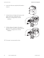
6. Loosen all 6 lid screws and pull the lid forwards to
remove it.
7. Verify the absence of voltage L with respect to N at
the AC clamp with an appropriate meter.
☑ If there is a voltage present, check the
installation.
8. Verify the absence of voltage L with respect to
ground at the AC clamp with an appropriate meter.
☑ If there is a voltage present, check the
installation.
☑ The inverter is now open and is not live.
58
SMC9-11TLRP-IEN100640
Installation Guide
SMA Solar Technology AG
Opening and Closing
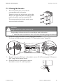
7.3 Closing the Inverter
1. Secure the lid with the 6 screws and the
corresponding tooth lock washers.
Tighten the screws with 6 Nm torque in the order
shown on the right hand side. The toothing of the
tooth lock washers must face toward the lid.
The inverter packing list includes another spare
screw and tooth lock washer.
DANGER!
Danger to life due to live enclosure lid!
The grounding of the enclosure lid is ensured by the tooth lock washers.
• Fasten the tooth lock washers for all 6 screws with the toothing facing toward the lid.
2. Check the DC plug connector for correct polarity and connect it.
To release the plug connectors see section 7.2 ”Opening the Inverter” (page 56).
3. Close all unnecessary DC inputs as described in section 5.5.4 ”Connecting the PV Generator
(DC)” (page 36) to seal the inverter.
4. Check the Electronic Solar Switch for wear as
described in section 8.2 and firmly attach.
Installation Guide
SMC9-11TLRP-IEN100640
59
Opening and Closing
SMA Solar Technology AG
NOTICE!
Manipulating the connector in the handle can damage the Electronic Solar
Switch!
The connector inside the handle must remain movable in order to ensure proper contact.
Tightening the screw voids all warranty claims and creates a fire risk.
• Do not tighten the connector screw in the Electronic Solar Switch handle.
NOTICE!
Damage to Electronic Solar Switch!
If not plugged correctly, the Electronic Solar Switch can be damaged by high voltages.
• Connect the holder firmly on to the socket of the Electronic Solar Switch.
• Make sure that the device is securely in place.
5. Switch on the line circuit breaker.
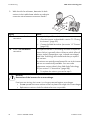
6. Check whether the display and the LEDs indicate
normal operating mode (see section
6 ”Commissioning” (page 55)).
☑ The inverter is now closed and in operation.
60
SMC9-11TLRP-IEN100640
Installation Guide
SMA Solar Technology AG
Maintenance and Cleaning
8 Maintenance and Cleaning
8.1 Checking Heat Dissipation
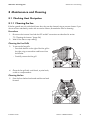
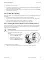
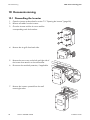
8.1.1 Cleaning the fan
If the fan guards are only soiled with loose dust, they can be cleaned using a vacuum cleaner. If you
do not achieve satisfactory results with a vacuum cleaner, dismantle the fans for cleaning.
Procedure
1. Disconnect the inverter from both the DC and AC connections as described in section
7.2 ”Opening the Inverter” (page 56).
2. Wait for the fans to stop rotating.
Cleaning the Fan Grills
3. To remove the fan grills:
– Press both latches on the right of the fan grill to
the right using a screwdriver and loosen from
the bracket.
– Carefully remove the fan grill.
4. Clean the fan grill with a soft brush, a paint brush,
a cloth or compressed air.
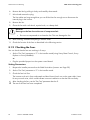
Cleaning the fan
5. Press the front latches backward and the rear latch
forward.
Installation Guide
SMC9-11TLRP-IEN100640
61
Maintenance and Cleaning
SMA Solar Technology AG
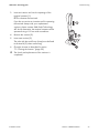
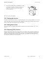
6. Remove the fan by pulling it slowly and carefully downwards.
7. Unlock and remove the plug.
The fan cables are long enough that you can lift the fans far enough out to disconnect the
internal plug in the inverter.
8. Remove the fan.
9. Clean the fan with a soft brush, a paint brush, or a damp cloth.
NOTICE!
Damage to the fan due to the use of compressed air.
• Do not use compressed air to clean the fan. This can damage the fan.
10. After cleaning, assemble everything in reverse order.
11. Check the function of the fans as described in the following section.
8.1.2 Checking the Fans
You can check that the fans are working in 2 ways:
• Set the "Fan Test" parameter to "1" in the installer mode (using Sunny Data Control, Sunny
Explorer or Sunny WebBox).
or
• Plug the provided jumper into the system control board.
Setting Parameters
1. Request the installer password on the SMA Serviceline (contact: see Page 90).
2. Set the "Fan Test" parameter to "1" in the installer mode.
3. Check the fans' air flow.
The inverter sucks air in from underneath and then blows it back out on the upper sides. Listen
for any unusual noise, which could indicate incorrect installation or that the fans are faulty.
4. After checking the fans, set the "Fan Test" parameter back to 0.
☑ The test of the fans has been completed.
62
SMC9-11TLRP-IEN100640
Installation Guide
SMA Solar Technology AG
Maintenance and Cleaning
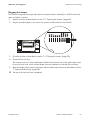
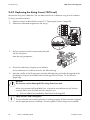
Plugging the Jumper
The inverter recognizes the jumper only after the system has been restarted (i.e. all LEDs must have
gone out before a restart).
1. Open the inverter as described in section 7.2 ”Opening the Inverter” (page 56).
2. Plug the provided jumper in the slot on the system control board as shown below.
3. Close the inverter as described in section 7.3 ”Closing the Inverter” (page 59).
4. Check the fans' air flow.
The inverter sucks air in from underneath and then blows it back out on the upper sides. Listen
for any unusual noise, which could indicate incorrect installation or that the fans are faulty.
5. After checking the fans, remove the jumper. Open and close the inverter as described in section
7 ”Opening and Closing” (page 56).
☑ The test of the fans has been completed.
Installation Guide
SMC9-11TLRP-IEN100640
63
Maintenance and Cleaning
SMA Solar Technology AG
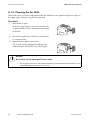
8.1.3 Cleaning the Air Grills
The inverter sucks air in from underneath via the fan and blows it out again through the air grills on
the upper sides. Clean the air grills if they are dirty.
Procedure
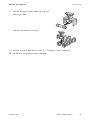
1. Remove the air grills.
Insert your finger above in the space between the
air grills and the enclosure and remove the air grills
to the side.
2. Clean the air grills with a soft brush, a paint brush,
or compressed air.
3. Re-attach the air grills to the inverter.
The air grills must be attached according to the
inside inscription ("links/left" and "rechts/right").
NOTICE!
The inverter can be damaged if insects enter!
• The air grills must not be removed permanently, because otherwise the device is not
protected against the entrance of insects.
64
SMC9-11TLRP-IEN100640
Installation Guide
SMA Solar Technology AG
Maintenance and Cleaning
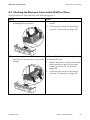
8.2 Checking the Electronic Solar Switch (ESS) for Wear
Check the Electronic Solar Switch for wear before plugging it in.
Result
Action
☑ The metal tongues inside the connector are 1. Securely attach the Electronic Solar Switch
not damaged or discolored.
handle.
2. Commission the inverter as described in
section 6 ”Commissioning” (page 55).
☑ The metal tongues inside the connector
The Electronic Solar Switch can no longer reliably
have a brown discoloration or are burned disconnect the DC side.
through.
1. Replace the Electronic Solar Switch handle
before attaching it again (for the order
number see section 12 ”Accessories”
(page 88).
2. Commission the inverter as described in
section 6 ”Commissioning” (page 55).
Installation Guide
SMC9-11TLRP-IEN100640
65
Troubleshooting
SMA Solar Technology AG
9 Troubleshooting
If the inverter displays other blink codes or error messages as detailed below, contact the SMA
Serviceline.
In the user manual provided, you will also find a description of the display messages during operation,
the status messages and measuring channels.
Do not try to carry out repairs other than those described here. Instead, use the SMA Solar
Technology AG 24-hour replacement service (the inverter will be ready for dispatch within 24 hours
and sent to a forwarding agency) and repair servic e.
9.1 LED Codes
Green
Glows continuously
Red
Is not glowing
Glows continuously
Flashes quickly
(3 x per second)
Flashes slowly
Is not glowing
Glows continuously
Yellow
Is not glowing
Is not glowing
Glows continuously
Is not glowing
Is not glowing
Status
OK (feeding operation)
Fault
OK (initialization)
OK (stop)
Fault
Is not glowing
Is not glowing
OK (waiting, grid
monitoring)
Is not glowing
Is not glowing
Fault
OK (derating)
Is not glowing
OK (nighttime
deactivation)
Fault
Fault
Fault
Warning
(see section 9.4 )
(1 x per second)
Briefly goes out
Glows continuously
(Approx. 1x per second) Is not glowing
Is not glowing
Is not glowing
Glows continuously
Not relevant
66
Blinks
SMC9-11TLRP-IEN100640
Glowing/blinking
Is not glowing
Glowing/blinking
Not relevant
Installation Guide
SMA Solar Technology AG
Troubleshooting
9.2 Error Messages
When a disturbance occurs, the inverter generates a message, which depends on the operating mode
and the type of the detected disturbance.
Message
!!PV-Overvoltage!!
Description and corrective measure
Overvoltage at DC input.
!DISCONNECT DC!
Overvoltage can destroy the inverter.
Corrective measures
Immediately disconnect the inverter from the grid.
1. Turn off the line circuit breaker.
2. Remove the Electronic Solar Switch.
3. Disconnect all the DC plug connectors.
4. Check DC voltage:
– If the DC voltage exceeds the maximum input voltage, check the
plant design or contact the person who installed the PV
generator.
– If the DC voltage is under the maximum input voltage, reconnect
the inverter to the PV generator as described in section
5.5.4 ”Connecting the PV Generator (DC)” (page 36).
ACVtgRPro
If the message occurs again, disconnect the inverter again and contact
the SMA Serviceline (see section 13 ”Contact” (page 90)).
The 10-minute-average grid voltage is no longer within the permissible
range. This can be caused by either of the following:
• The grid voltage at the connection point is too high.
• The grid impedance at the connection point is too high.
The inverter disconnects to assure compliance with the voltage quality of
the grid.
Corrective measures
Check the grid voltage at the connection point of the inverter:
• If, due to the local grid conditions, the grid voltage is 253 V or
more, ask the utility operator whether the voltage at the feed-in
point can be adjusted, or whether they agree to an alteration of the
threshold value of the ACVtgRPro parameter to monitor the voltage
quality.
CAN
• If the grid voltage is continually within the acceptable range, and
this error is still displayed, contact the SMA Serviceline.
Internal communication fault.
Corrective measures
• If this fault occurs often, contact the SMA Serviceline.
Installation Guide
SMC9-11TLRP-IEN100640
67
Troubleshooting
SMA Solar Technology AG
Message
Check L-N-PE
Check Varistor
Description and corrective measure
L and N are swapped at the AC connection or PE is not connected.
Corrective measures
• Check the AC connection
At least one of the varistors is defective.
Corrective measures
• Check the function of the varistors as described in section
9.4.1 ”Checking the Function of the Varistors (<Check Varistor>)”
(page 75).
At least one string fuse is defective.
Corrective measures
DC fuse
• Check and if necessary replace the string fuses, as described in
section 9.4.2 ”Replacing the String Fuses (<DC fuse>)” (page 78).
The "Derating" operating mode is a normal operating mode which may
occur occasionally and can have several causes.
Derating
Once the inverter enters the "Derating" mode, it will display the "Derating"
warning until the next total shutdown of the device (at the end of the day).
Corrective measures
• Check heat dissipation, as described in Section 8.1 ”Checking
Heat Dissipation” (page 61).
The inverter has detected a drastic change in the differential current. The
integrated differential current monitoring system plays an important part
in ensuring personal safety.
dI-Bfr
dI-Srr
A drastic change in the differential current can be caused by a sudden
grounding fault, failure current or an actual fault in the device. The
inverter disconnects from the grid.
Corrective measures
• If the message "Fault current-Bfr" or "Fault current-Srr" appears for
no obvious reason, verify whether the plant insulation might have a
ground fault, as described in section 9.3 ”The Red LED Glows
Continuously (Ground Fault)” (page 74).
Transition disturbance during reading or writing of EEPROM data. The
data is not relevant for safe operation.
EEPROM
EEPROM dBh
• The disturbance has no effect on the performance of the inverter.
EEPROM data is defective, the inverter has switched itself off because the
loss of data has disabled important functions of the inverter.
Corrective measures
• Contact the SMA Serviceline.
68
SMC9-11TLRP-IEN100640
Installation Guide
SMA Solar Technology AG
Message
EeRestore
Fac-Bfr
Fac-Srr
FacFast
Troubleshooting
Description and corrective measure
One of the duplicate data sets in the EEPROM is defective and has been
reconstructed without loss of data.
• The error message only serves to inform you and has no effect on
the performance of the inverter.
The grid frequency is no longer within the permissible range
("Bfr" / "Srr" / "Fast" is an internal message that has no meaning for the
user). For safety reasons, the inverter disconnects itself from the grid.
Corrective measures
• Check the grid connection and contact the utility operator if
necessary.
Fault Curr Meas
Fault Curr Meas-Srr
HW-Signal
• If the grid frequency is within the tolerance range, yet "Fac-Bfr,"
"Fac-Srr" or "FacFast" faults are still being displayed, please contact
the SMA Serviceline.
Deviation in the differential current measurement / differential current
If this fault message is displayed repeatedly, it means that inverter
operation is permanently disabled.
Corrective measures
• Contact the SMA Serviceline.
Corrective measures
• Contact the SMA Serviceline.
Corrective measures
Iac-DC_Offs-Srr
• If this fault occurs often, contact the SMA Serviceline.
A grid disturbance has occurred.
Corrective measures
• Check the grid conditions.
IGBTs
Imax
• Contact the SMA Serviceline if this problem occurs often or several
times in succession.
The internal hardware monitoring system has detected a fault in the
power electronics.
Corrective measures
• Contact the SMA Serviceline.
Overcurrent on the AC side. This message is displayed if the current in the
AC grid is greater than specified.
Corrective measures
• Check the system design and grid conditions.
Installation Guide
SMC9-11TLRP-IEN100640
69
Troubleshooting
SMA Solar Technology AG
Message
MSD-dI
Description and corrective measure
Internal measurement comparison fault or hardware defect.
Corrective measures
MSD-Fac
• If this fault occurs often, contact the SMA Serviceline.
Internal measurement comparison fault or hardware defect.
Corrective measures
MSD-Vac
• If this fault occurs often, contact the SMA Serviceline.
Internal measurement comparison fault or hardware defect.
Corrective measures
MSD-Timeout
• If this fault occurs often, contact the SMA Serviceline.
Internal measurement comparison fault or hardware defect.
Corrective measures
offset
• If this fault occurs often, contact the SMA Serviceline.
Fault in the acquisition of measurement data.
Corrective measures
PowerBalance
REL_INV_CLOSE
REL_GRID_CLOSE
• If this fault occurs often, contact the SMA Serviceline.
The Sunny Mini Central is part of a three-phase system with two further
Sunny Mini Centrals. This is equipped with the SMA Power Balancer for
preventing asymmetric loads. The operating parameter "PowerBalancer"
is set to "PhaseGuard" or "FaultGuard".
Corrective measures
• For more detailed descriptions of the operation modes
"PhaseGuard" and "FaultGuard", please refer to section
5.6 ”Connection of the SMA Power Balancer” (page 39).
A grid relay does not close. The inverter checks the relays connecting it
to the grid before feeding power into the grid. If the grid relays do not
function properly, the inverter does not connect to the grid for safety
reasons.
Corrective measures
• Contact the SMA Serviceline.
70
SMC9-11TLRP-IEN100640
Installation Guide
SMA Solar Technology AG
Message
REL_INV_OPEN
REL_GRID_OPEN
Troubleshooting
Description and corrective measure
A grid relay does not open. The inverter checks the relays connecting it
to the grid before feeding power into the grid. If the grid relays do not
function properly, the inverter does not connect to the grid for safety
reasons.
Corrective measures
• If this fault message is displayed repeatedly, it means that inverter
operation is permanently disabled. If the inverter is equipped with
a communication interface, try to rectify the fault using a
communication product.
Riso
• Should this be unsuccessful, contact the SMA Serviceline.
The electrical insulation between the PV system and ground is faulty. The
resistance between the DC plus and/or DC minus connection and ground
is outside the defined limit range.
Corrective measures
• Check the plant insulation.
Riso-Sense
• Check the plant for ground faults as described in section 9.3 ”The
Red LED Glows Continuously (Ground Fault)” (page 74).
The insulation measurement has failed.
Corrective measures
ROM
• If this fault occurs often, contact the SMA Serviceline.
The inverter's firmware is faulty.
Corrective measures
SD-DI-Wandler
• If this fault occurs often, contact the SMA Serviceline.
The inverter has detected an insulation fault on the DC side.
Corrective measures
• Check the plant insulation.
SD-Imax
SD-WR-Bruecke
• Check the plant for ground faults as described in section 9.3 ”The
Red LED Glows Continuously (Ground Fault)” (page 74).
The inverter has detected an overcurrent on the AC side. It disconnects
from the grid for safety reasons and then attempts to reconnect to the
grid.
Corrective measures
• If this fault occurs often, contact the SMA Serviceline.
The inverter has detected a fault in the power electronics. It disconnects
from the grid and then attempts to reconnect to the grid.
Corrective measures
• If this fault continues to occur, contact the SMA Serviceline.
Installation Guide
SMC9-11TLRP-IEN100640
71
Troubleshooting
SMA Solar Technology AG
Message
Shutdown
Description and corrective measure
Temporary inverter fault.
Corrective measures
STM Timeout
Vac-Bfr
Vac-Srr
• Contact the SMA Serviceline.
Internal program run fault.
Corrective measures
• If this fault occurs often, contact the SMA Serviceline.
The grid voltage on line 2 is no longer within the permissible range
("Bfr" or "Srr" is an internal message that has no meaning for the user).
This code can be caused by any of the following conditions:
• Grid disconnected (line circuit breaker, fuse),
• AC cable is broken or
• AC cable is highly resistive.
For safety reasons, the inverter disconnects itself from the grid.
Corrective measures
• Check the grid current and grid connection on the inverter.
• If the grid voltage lies outside the acceptable range because of
local grid conditions, ask the utility operator if the voltages can be
adjusted at the feed-in point or if they agree to changes in the
values of the monitored operational limits (operating parameters:
Vac-Min and Vac-Max).
• If the grid frequency is within the tolerable range, yet "Vac-Bfr," or
"Vac-Srr" faults are still being displayed, please contact the SMA
Serviceline.
72
SMC9-11TLRP-IEN100640
Installation Guide
SMA Solar Technology AG
Message
VpvMax
Vpv-Max
Troubleshooting
Description and corrective measure
Overvoltage at DC input. The inverter may be damaged.
Corrective measures
Immediately disconnect the inverter from the grid!
1. Turn off the line circuit breaker.
2. Remove the Electronic Solar Switch.
3. Disconnect all the DC plug connectors.
4. Check DC voltage:
– If the DC voltage exceeds the maximum input voltage, check the
plant design or contact the person who installed the PV
generator.
– If the DC voltage is under the maximum input voltage, reconnect
the inverter to the PV generator as described in section
5.5.4 ”Connecting the PV Generator (DC)” (page 36).
UZWK-Max
UzwkMax
Watchdog
If the message occurs again, disconnect the inverter again and contact
the SMA Serviceline (see section 13 ”Contact” (page 90)).
The internal hardware monitor has detected an overvoltage condition in
the intermediate circuit of the inverter.
Corrective measures
• If this fault occurs often, contact the SMA Serviceline.
Internal program run fault.
Watchdog-Srr
Corrective measures
• If this fault occurs often, contact the SMA Serviceline.
Installation Guide
SMC9-11TLRP-IEN100640
73
Troubleshooting
SMA Solar Technology AG
9.3 The Red LED Glows Continuously (Ground Fault)
The inverter has detected a ground fault in the PV generator.
Proceed as follows to find it:
1. Disconnect the inverter from both the DC and AC connections as described in section
7.2 ”Opening the Inverter” (page 56).
NOTICE!
Excessive voltages can destroy the measuring device!
• Only use measuring devices with a DC input voltage range up to at least 1000 V.
2. Measure the voltages between the plus and minus
pole of a string against the ground potential.
☑ If voltage is found, there is a ground fault in the
corresponding string.
DANGER!
Risk of lethal electric shock!
In case of a ground fault, the PV generator may carry high voltages.
• Do not touch the frame of the PV generator.
• Wait until no voltage can be measured.
• Do not connect strings with ground faults to the inverter.
The approximate position of the ground fault can be determined from the ratio of the measured
voltages between plus against ground potential and minus against ground potential.
Example:
The ground fault is between the second and third module in this case.
74
SMC9-11TLRP-IEN100640
Installation Guide
SMA Solar Technology AG
Troubleshooting
3. Repeat step 2 for each string.
4. The installer of the PV generator must remedy the ground fault in the affected string before you
may reconnect the string to the inverter.
5. Restart the inverter as described in section 7.3 ”Closing the Inverter” (page 59), but without
reconnecting the faulty string.
9.4 The Red LED is Flashing
A flashing red LED can have different causes and depends on the corresponding fault indication on
the display:
• <Check Varistor> display message: At least one of the varistors is defective
(see section 9.4.1 ”Checking the Function of the Varistors (<Check Varistor>)” (page 75)).
• <DC fuse> display message: At least one of the string fuses is defective
(see section 9.4.2 ”Replacing the String Fuses (<DC fuse>)” (page 78)).
9.4.1 Checking the Function of the Varistors (<Check Varistor>)
Varistors are wearing parts. Their functional efficiency diminishes with age or following repeated
responses as a result of overvoltages. It is therefore possible that one of the thermally monitored
varistors has lost its protective function.
Position of Varistors
You can determine the position of the varistors with the help of the illustration below.
Observe the following allocation of the
terminals:
• Terminal A: outer terminal (varistor
connection with loop [crimp])
• Terminal B: middle terminal
• Terminal C: outer terminal (varistor
connection without loop [crimp])
You can check the varistors as follows:
1. Open the inverter as described in section 7.2 ”Opening the Inverter” (page 56).
Installation Guide
SMC9-11TLRP-IEN100640
75
Troubleshooting
SMA Solar Technology AG
2. With the aid of a multimeter, determine for both
varistors in the installed state whether a conductive
connection exists between connectors B and C.
Result
☑ There is a conductive
connection:
☑ There is no conductive
connection:
Action
There is probably a different fault in the inverter.
• Close the inverter as described in section 7.3 ”Closing
the Inverter” (page 59).
• Contact the SMA Serviceline (see section 13 ”Contact”
(page 90)).
The respective varistor is not working and must be replaced.
Varistor failure is generally due to influences which affect all
varistors similarly (temperature, age, induced overvoltage).
SMA Solar Technology AG recommends that you replace
both varistors.
The varistors are specially manufactured for use in the inverter
and are not commercially available. You must order
replacement varistors directly from SMA Solar Technology
AG (see section 12 ”Accessories” (page 88)).
• To replace the varistors, proceed to step 3.
NOTICE!
Destruction of the inverter due to overvoltage.
If varistors are missing, the inverter is no longer protected against overvoltages.
• Do not operate the inverter without varistors in plants with a high risk of overvoltages.
• Replacement varistors should be obtained as soon as possible.
76
SMC9-11TLRP-IEN100640
Installation Guide
SMA Solar Technology AG
Troubleshooting
3. Insert an insertion tool into the openings of the
terminal contacts (1).
☑ This releases the terminals.
If you do not receive an insertion tool for operating
the terminal clamps with your replacement
varistors, please contact SMA Solar Technology
AG. As an alternative, the terminal contacts can be
operated using a 3.5 mm wide screwdriver.
4. Remove the varistor (2).
5. Insert new varistor (3).
The pole with the small loop (crimp) must be fitted
to terminal A (3) when remounting.
6. Close the inverter as described in section
7.3 ”Closing the Inverter” (page 59).
☑ The check and replacement of the varistors is
completed.
Installation Guide
SMC9-11TLRP-IEN100640
77
Troubleshooting
SMA Solar Technology AG
9.4.2 Replacing the String Fuses (<DC fuse>)
At least one string fuse is defective. You can detect which fuse is defective using a circuit indicator.
To do so, proceed as follows:
1. Open the inverter as described in section 7.2 ”Opening the Inverter” (page 56).
2. Observe the illustrated assignment to the strings.
3. All fuse extractors must be consecutively removed
with the string fuses.
Note the string assignment.
4. Check the conductivity using the circuit indicator.
A non-conductive fuse indicates a fault in the affected string.
5. Have the installer of the PV generator check the affected string and order the upgrade kit for
the defective string fuse from SMA Solar Technology AG (see section 12 ”Accessories”
(page 88)).
NOTICE!
The inverter can be damaged if the string fuses burn out!
When using commercially available fuses, it cannot be ensured that they will function
correctly and in case of a fault, the fuses may burn out.
• Only use add-on kits provided by SMA Solar Technology AG.
Equip all slots with a string fuse
To ensure that the fuse monitoring function is working properly, all 5 slots must be equipped
with the appropriate fuses at all times. This also applies if fewer strings are connected!
78
SMC9-11TLRP-IEN100640
Installation Guide
SMA Solar Technology AG
Troubleshooting
6. Insert the string fuse from the add-on kit in the fuse
extractor provided.
7. Insert the fuse extractors in the slots.
8. Close the inverter as described in section 7.3 ”Closing the Inverter” (page 59).
☑ The defective string fuses have been replaced.
Installation Guide
SMC9-11TLRP-IEN100640
79
Decommissioning
SMA Solar Technology AG
10 Decommissioning
10.1 Dismantling the Inverter
1. Open the inverter as described in section 7.2 ”Opening the Inverter” (page 56).
2. Remove all cables from the inverter.
3. Close the inverter with the 6 screws and the
corresponding tooth lock washers.
4. Remove the air grills from both sides.
5. Remove the two screws on the left and right side of
the inverter that attach it to the wall bracket.
6. Disconnect the anti-theft protection, if applicable.
7. Remove the inverter upwards from the wall
mounting bracket.
80
SMC9-11TLRP-IEN100640
Installation Guide
SMA Solar Technology AG
Decommissioning
8. Use the side handles (above and below) or a steel
rod (maximum diameter 30 mm) to transport the
inverter. The rod must be pushed through the
enclosure openings.
☑ The inverter is dismantled.
10.2 Packing the Inverter
If possible, always pack the inverter in its original packaging. If it is no longer available, you can also
use an equivalent carton. The carton must be completely closeable, have a handle system and be
made to support both the weight and size of the inverter.
10.3 Storing the Inverter
Store the inverter in a dry place where ambient temperatures are always between -25 °C and
+60 °C.
10.4 Disposing of the Inverter
Dispose of the inverter at the end of its service life in accordance with the disposal regulations for
electronic waste which apply at the installation location at that time. Alternatively, send it back to
SMA Solar Technology AG with shipping paid by sender, and labeled "ZUR ENTSORGUNG"
("for disposal") (contact see section Page 90)
Installation Guide
SMC9-11TLRP-IEN100640
81
Technical Data
SMA Solar Technology AG
11 Technical Data
11.1 Sunny Mini Central 9000TL / 10000TL / 11000TL
SMC
9000TL-10
PV generator connection data
Max. PV input voltage
Input voltage, MPP range
PV start voltage, adjustable
Max. input current
Max. input power
Voltage ripple
Internal consumption during
operation
SMC
11000TL-10
700 V a)
UPV 0
UPV
UPV Start
IPVMax
PDC
Upp
SMC
10000TL-10
(Based on -10 °C cell temperature)
333 V ... 500 V DC
400 V
400 V
400 V
28 A
31 A
34 A
9300 W
10350 W
11400 W
< 10 % of the input voltage
<8W
a)The maximum open circuit voltage, which can occur at a cell temperature of -10 °C, may not exceed the maximum input
voltage.
Grid connection data
AC nominal power
Max. AC power
Nominal AC current
Max. AC current
Max. fuse protection
Harmonic distortion of output current
(at KUgrid < 2 %, PAC > 0.5 PACNom)
Nominal operating voltage
Voltage range
(extended operating range)
Nominal operating frequency
Frequency range
PACNom
PACMax
IACNom
IACMax
KIAC
SMC9-11TLRP-IEN100640
10000 W
10000 W
44 A
44 A
80 A
<4%
11000 W
11000 W
48 A
48 A
UACnom
UAC
220 V / 230 V / 240 V
180 V ... 260 V
fACnom
fAC
50 Hz / 60 Hz
50 Hz: 45.5 Hz ... 54.5 Hz
(extended operating range)
Power factor (at nominal output
cos ϕ
power)
Overvoltage category
Test voltage (50 Hz)
Test surge voltage
Internal consumption in night mode
82
9000 W
9000 W
40 A
40 A
60 Hz: 55.5 Hz ... 64.5 Hz
1
III
2.15 kV
4 kV (serial interface: 6 kV)
0.15 W
Installation Guide
SMA Solar Technology AG
Technical Data
SMC
9000TL-10
General data
EC Declaration of Conformity
SMC
10000TL-10
SMC
11000TL-10
Enclosed documentation package
Download area www.SMA.de/en
468 mm x 613 mm x 242 mm (approx.)
approx. 35 kg
IP65
Dimensions (W x H x D)
Weight
Protection rating in accordance with
DIN EN 60529
Climatic conditions according to DIN EN 50178:1998-04:
Location of type C:
Transport of type E:
Operation temperature range
Max. operating altitude
Topology
Fan connection
Protection class
Noise emission (typical)
Protective function DC side
All-pole disconnection unit on the DC input side
Overvoltage protection
Personnel protection
Pole confusion protection
Protective function AC side
Short circuit proof
Installation Guide
Class 4K4H
Extended temperature range:
-25 °C to +60 °C
Extended humidity range:
0 ... 100 %
Extended air pressure range:
70 kPa to 106 kPa
class 2K3
Temperature range:
– 25 °C ... +70 °C
– 25 °C ... +60 °C
3000 m above mean sea level
Transformerless
Designed for safe disconnection in accordance with
DIN EN 50178:1998-04
I
≤ 42 dB(A)
≤ 45 dB(A)
≤ 46 dB(A)
Electronic Solar Switch,
DC plug system SUNCLIX
Thermally monitored varistors
Insulation monitoring (Riso > 1 M Ω )
Via short-circuit diode
Current control
SMC9-11TLRP-IEN100640
83
Technical Data
SMA Solar Technology AG
SMC
SMC
SMC
9000TL-10
10000TL-10 11000TL-10
Automatic disconnection device
(SMA Grid Guard 2.1)
All-pole disconnection unit grid side
Communication interfaces
RS485 (galvanically isolated)
Radio
Bluetooth® Wireless Technology
optional
optional
optional
Electronic Solar Switch (ESS)
Electrical service life
(in the event of a short circuit, with a nominal
current of 35 A)
Maximum switching current
Maximum switching voltage
Maximum PV power
Protection rating when plugged
Protection rating when unplugged
Efficiency
Max. efficiency
European efficiency
ηmax
ηeuro
Min. 50 switching processes
35 A
800 V
Approx. 12 kW
IP65
IP21
97.6 %
98 %
97.5 %
97.5 %
Efficiency curve
84
SMC9-11TLRP-IEN100640
Installation Guide
SMA Solar Technology AG
Technical Data
11.2 Sunny Mini Central 9000TL / 10000TL / 11000TL with
Reactive Power Control
SMC
SMC
SMC
9000TLRP-10 10000TLRP-10 11000TLRP-10
PV generator connection data
Max. PV input voltage
UPV 0
Input voltage, MPP range
PV start voltage, adjustable
Max. input current
Max. input power
UPV
UPV Start
IPVMax
PDC
(at cos ϕ = 1)
Voltage ripple
Upp
Internal consumption during operation
a)
700 V a)
(Based on -10 °C cell temperature)
333 V ... 500 V DC
400 V
400 V
400 V
28 A
31 A
34 A
9300 W
10350 W
11400 W
< 10 % of the input voltage
<8W
The maximum open circuit voltage, which can occur at a cell temperature of -10 °C, may not exceed the maximum input voltage.
Grid connection data
AC nominal power
Max. AC power
Nominal AC current
Max. AC current
Max. fuse protection
Harmonic distortion of output current
(at KUgrid < 2 %, PAC > 0.5 PACNom)
Nominal operating voltage
Voltage range
(extended operating range)
Nominal operating frequency
Frequency range
(extended operating range)
Displacement power factor,
configurable
Overvoltage category
Test voltage (50 Hz)
Test surge voltage
Internal consumption in night mode
Installation Guide
SACNom
SACMax
IACNom
IACMax
KIAC
9000 VA
9000 VA
40 A
40 A
10000 VA
10000 VA
44 A
44 A
80 A
<4%
11000 VA
11000 VA
48 A
48 A
UACnom
UAC
220 V / 230 V / 240 V
180 V ... 260 V
fACnom
fAC
50 Hz / 60 Hz
50 Hz: 45.5 Hz ... 54.5 Hz
60 Hz: 55.5 Hz ... 64.5 Hz
0.8overexcited ... 0.8underexcited
cos ϕ
III
2.15 kV
4 kV (serial interface: 6 kV)
0.15 W
SMC9-11TLRP-IEN100640
85
Technical Data
SMA Solar Technology AG
SMC
SMC
SMC
9000TLRP-10 10000TLRP-10 11000TLRP-10
General data
EC Declaration of Conformity
Enclosed documentation package
Download area www.SMA.de/en
Dimensions (W x H x D)
468 mm x 613 mm x 242 mm (approx.)
Weight
approx. 35 kg
Protection rating in accordance with
IP65
DIN EN 60529
Climatic conditions according to DIN EN 50178:1998-04:
Location of type C:
Class 4K4H
Extended temperature range:
-25 °C to +60 °C
Extended humidity range:
0 ... 100 %
Extended air pressure range:
Transport of type E:
70 kPa to 106 kPa
class 2K3
Temperature range:
Operation temperature range
Max. operating altitude
Topology
Fan connection
Protection class
Noise emission (typical)
Protective function DC side
All-pole disconnection unit on the DC input side
Overvoltage protection
Personnel protection
Pole confusion protection
86
SMC9-11TLRP-IEN100640
– 25 °C ... +70 °C
– 25 °C ... +60 °C
3000 m above mean sea level
Transformerless
Designed for safe disconnection in accordance with
DIN EN 50178:1998-04
I
≤ 42 dB(A)
≤ 45 dB(A)
≤ 46 dB(A)
Electronic Solar Switch,
DC plug system SUNCLIX
Thermally monitored varistors
Insulation monitoring (Riso > 1 M Ω )
Via short-circuit diode
Installation Guide
SMA Solar Technology AG
Technical Data
SMC
SMC
SMC
9000TLRP-10 10000TLRP-10 11000TLRP-10
Protective function AC side
Short circuit proof
All-pole disconnection unit grid side
Current control
Automatic disconnection device
(SMA Grid Guard 2.1)
Communication interfaces
RS485 (galvanically isolated)
Bluetooth
optional
optional
Electronic Solar Switch (ESS)
Electrical service life (in the event of a short
circuit, with a nominal current of 35 A)
Maximum switching current
Maximum switching voltage
Maximum PV power
Protection rating when plugged
Protection rating when unplugged
Efficiency
Max. efficiency
European efficiency
ηmax
ηeuro
min. 50 switching processes
35 A
800 V
Approx. 12 kW
IP65
IP21
97.7 %
97.3 %
Efficiency curve
Installation Guide
SMC9-11TLRP-IEN100640
87
Accessories
SMA Solar Technology AG
12 Accessories
You will find the corresponding accessories and replacement parts for your product In the following
overview. If required, you can order these from SMA Solar Technology AG or your dealer.
Description
Brief description
SMA order number
SMC 9000TL-10 SMC 9000TLRP-10
SMC 10000TL-10 SMC 10000TLRP-10
8 A string fuses
10 A string fuses
12 A string fuses
16 A string fuses
20 A string fuses
SMA Power Balancer
Y cable
RS485 upgrade kit
Radio upgrade kit
Bluetooth upgrade kit
Power Reducer Box
Replacement varistors
Insertion tool for
replacing the varistors
88
Add-on kit with 5 8 A fuses
(incl. fuse protector)
Add-on kit with 5 10 A fuses
(incl. fuse protector)
Add-on kit with 5 12 A fuses
(incl. fuse protector)
Add-on kit with 5 16 A fuses
(incl. fuse protector)
Add-on kit with 5 20 A fuses
(incl. fuse protector)
Connecting cable (2 x 2 m)
for SMA Power Balancer
connector system
RS485 interface
Radio Piggy-Back for
upgrading a Sunny Mini
Central for communication
with Sunny Beam, including
antenna, coaxial cable, and
PG threaded joint (metal)
Bluetooth communication
interface
Power Reducer Box
Set of thermally monitored
varistors (2 pcs.) including
insertion tool
Installation tool for varistors
SMC9-11TLRP-IEN100640
SMC 11000TL-10 SMC 11000TLRP-10
FUSEKIT 8A-NR
FUSEKIT 10A-NR
FUSEKIT 12A-NR
FUSEKIT 16A-NR
FUSEKIT 20A-NR
PBL-YCABLE-10
485PB-SMC-NR
BEAMPB-NR
--
On request
POWERREDUCERBOX
MSWR-TV 7
SB-TVWZ
Installation Guide
SMA Solar Technology AG
Description
Accessories
Brief description
SMA order number
SMC 9000TL-10 SMC 9000TLRP-10
SMC 10000TL-10 SMC 10000TLRP-10
Electronic Solar Switch ESS handle replacement part
Air grills
Air grill set "right and left" as
spare part
SUNCLIX DC plug
Field connector for conductor
connector
cross sections
2.5 mm² … 6 mm²
Installation Guide
SMC 11000TL-10 SMC 11000TLRP-10
ESS-HANDLE:04
45-7202
SUNCLIX-FC6-SET
SMC9-11TLRP-IEN100640
89
Contact
SMA Solar Technology AG
13 Contact
If you have technical problems concerning our products, contact the SMA Serviceline. We require the
following information in order to provide you with the necessary assistance:
• Inverter type
• Inverter serial number
• Type and number of the PV modules connected
• Optional equipment, e.g. communication devices
• Blink code or display message of the inverter
SMA Solar Technology AG
Sonnenallee 1
34266 Niestetal, Germany
www.SMA.de
SMA Serviceline
Inverters:
+49 561 9522 1499
Communication:
+49 561 9522 2499
Fax:
+49 561 9522 4699
E-Mail:
[email protected]
90
SMC9-11TLRP-IEN100640
Installation Guide
SMA Solar Technology AG
Legal Restrictions
The information contained in this document is the property of SMA Solar Technology AG. Publishing its content, either partially or
in full, requires the written permission of SMA Solar Technology AG. Any internal company copying of the document for the
purposes of evaluating the product or its correct implementation is allowed and does not require permission.
Exclusion of liability
The general terms and conditions of delivery of SMA Solar Technology AG shall apply.
The content of these documents is continually checked and amended, where necessary. However, discrepancies cannot be
excluded. No guarantee is made for the completeness of these documents. The latest version is available online at www.SMA.de
or from the usual sales channels.
Guarantee or liability claims for damages of any kind are excluded if they are caused by one or more of the following:
• Damages during transportation
• Improper or inappropriate use of the product
• Operating the product in an unintended environment
• Operating the product whilst ignoring relevant, statutory safety regulations in the deployment location
• Ignoring safety warnings and instructions contained in all documents relevant to the product
• Operating the product under incorrect safety or protection conditions
• Altering the product or supplied software without authority
• The product malfunctions due to operating attached or neighboring devices beyond statutory limit values
• In case of unforeseen calamity or force majeure
The use of supplied software produced by SMA Solar Technology AG is subject to the following conditions:
• SMA Solar Technology AG rejects any liability for direct or indirect damages arising from the use of software developed by
SMA Solar Technology AG. This also applies to the provision or non-provision of support activities.
• Supplied software not developed by SMA Solar Technology AG is subject to the respective licensing and liability agreements
of the manufacturer.
SMA Factory Warranty
The current guarantee conditions come enclosed with your device. These are also available online at www.SMA.de and can be
downloaded or are available on paper from the usual sales channels if required.
Trademarks
All trademarks are recognized even if these are not marked separately. Missing designations do not mean that a product or brand
is not a registered trademark.
The Bluetooth® word mark and logos are registered trademarks owned by Bluetooth SIG, Inc. and any use of such marks by SMA
Solar Technology is under license.
SMA Solar Technology AG
Sonnenallee 1
34266 Niestetal
Germany
Tel. +49 561 9522-0
Fax +49 561 9522-100
www.SMA.de
E-Mail: [email protected]
© 2004 to 2010 SMA Solar Technology AG. All rights reserved
Installation Guide
SMC9-11TLRP-IEN100640
91
4."4PMBS5FDIOPMPHZ"(
XXX4."EF