1
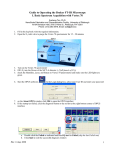
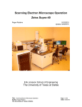
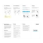
User Guide to Operating the JSM-6510LV SEM By Susheng Tan Nanoscale Fabrication and Characterization Facility, Petersen Institute of NaoScience and Engineering, University of Pittsburgh, 348 Benedum Hall, 3700 O’Hara Street, Pittsburgh, PA 15261 Office: M104 Benedum Hall; Phone: (412) 383-5978; Email: [email protected] I. Start the ChamberScope II. Start the SEM Main Menu III. User Login 1. Click the User Login of the operation menu tab. 2. Click the Logon/Log off button. 3. Select a user name from the user list, and click the Log On button. IV. Specimen Exchange 1. Prepare a specimen. Set the specimen on the specimen support, and adjust the specimen support so that the top of the specimen surface becomes in a same level with holder top. Be sure to fasten the specimen so that the top of the specimen surface does not protrude above the holder top. For such specimen as not electrically conductive, use a conductive paint to prevent the specimen from charging. Avoid setting the specimen containing unnecessarily water or oil, because it will contaminate inside the column. 2. Vent the specimen chamber. to change it to OFF . Click the HT icon Click Sample Setting of the operation menu tub. Click the Removing the specimen button. Click the VENT button. Use slow venting for samples such as powders which are easily scattered. First select Slow and then click the VENT button. e. After the light of the VENT button turns ON, the stage can be withdrawn to remove the specimen holder. 3. Setting the specimen. a. Click the Setting button. b. If the specimen protrudes above the holder, make sure to input the protruding sample height above the holder in the dialog box. c. Set the specimen holder onto the specimen stage. 4. Choose a recipe. a. Click the Choose a recipe button. b. From the displayed list of Standard recipe, select a recipe applicable to the sample, and click it. If you are not sure which recipe is applicable to the sample to be observed, select Universal. The standard observation conditions will be set. c. The operation navigation is changed to the setup observation condition menu. a. b. c. d. d. Set observation conditions according to the questions you will be asked. If the specimen is not electrically conductive, not coated and High Vacuum is being selected, Acc. voltage is automatically set at 1kV.Under this condition EDS analysis question becomes grayed out, because the amount of signals for EDS analysis is insufficient. e. Click the OK button. The observation condition will be set. 5. Evacuate the specimen chamber. a. Click the Evacuating the Chamber button. b. Close the specimen chamber, and click the EVAC button. Evacuation in the specimen chamber will start. 1. If the sample without coating or containing water is observed as it is, the vacuum mode must be set to the low-vacuum mode. 2. After the mode is selected, a message will appear. Follow the instructions in the message to change the vacuum mode. V. Observing a Specimen 1. Click the HT icon to get HT ON . 、 the and the icons to 2. Click the observe the image. 3. Move view of interest to the center of main screen with Click center. Double-click the left mouse button at any position in main screen. The double-clicked position moves to the center of the screen. 4. set it at necessary magnification. 5. Adjust the image quality by using the Contrast (X, Y) , Brightness , Focus and Stig buttons. Notes: Observation Condition: A). Difference of image quality depending on the value of the accelerating voltage Generally, the more fine structure of the specimen surface appears when using a low accelerating voltage than using a high accelerating voltage. B). Effect of the probe current You can obtain the higher magnification and the higher resolution for the SEM image, the smaller the probe diameter (spot size) to irradiate the specimen. However, the S/N (signal/noise) ratio depends on the probe current to irradiate the specimen. If you want to decrease the probe diameter, the probe current decreases. Therefore, you must select a probe current according to the magnification and the observation condition (such as the accelerating voltage and specimen tilt). C). Effect of the working distance (WD) on the image When you change the working distance (WD), in the short WD, although the depth of field becomes shallow, you can obtain high resolution; on the contrary, in the long WD, although the resolution decreases, the depth of field becomes deep. Moreover, in order to obtain a more optimum image quality, the brightness adjustment, astigmatism correction adjustment and focus adjustment become of importance. D). Observation of the nonconductive specimen and charge up When you irradiate a large current (high accelerating voltage and large spot size) electron beam on a nonconductive specimen, sometimes, electrons accumulate, in other words, charge up on the specimen. For such a specimen, you can reduce the charge-up to observe the specimen by using a low accelerating voltage or the low vacuum (LV) mode. Also, you can increase the emitted electrons by tilting the specimen, resulting in reducing the charge-up. 2 VI. Operating the Image Setting the Signal: 1. Click the signal , the accelerating voltage in the image data display. size 2. The relevant setting window is displayed. 3. Double-click on the desired setting in the list. Signal SEI BEIW AUX REF VII. Item Scan 1 Scan 2 Scan 3 Scan 4 Photo Freeze , working distance , or spot Data display SEI(Secondary electron image) BEC(Backscattered electron composition image) BET(Backscattered electron Topographic image) BES(Backscattered electron shadow image) AUX REF(Reflected electron image) Setting the Scan Rate: Explanation For searching field of view and adjusting image quality. To observe the image. To observe the image detail. To observe the more detail than the one at Scan 3 and acquire the image. To acquire the image and save the image automatically. An observation image becomes the frozen image. Note You can select the averaging coefficient and scan rate. A exposure marker can be displayed. You can select the averaging coefficient and scan rate. You can select the averaging coefficient and scan rate. You can select the scan rate. You can select the scan rate. When you want to cancel Freeze, click one of any scan icons. When you want to return to the previous scan rate before Freeze, click the Freeze icon again. VIII. Adjusting the Image Contrast/Brightness/Focus/Stig XY Place a mouse pointer on the button, and operate as follows. Coarse adjustment: While holding down the right button, move the mouse up (right) and down (left). Fine adjustment: While holding down the left button, move the mouse up (right) and down (left). Adjusting the image magnification continuously by scrolling the middle mouse wheel. 3 IX. Moving the Field View 1. Moving the stage in the vertical (Z) and tilt (T) directions: use the ChamberScope to monitor Z and/or T to avoid crash the specimen into detector and/or lense. X. Observing the backscattered electron image Features of backscattered electron images The brightness of the composition image becomes darker as the composition becomes lighter elements, and brighter as the composition becomes heavier elements. The topographic image looks like as if a light is illuminated from the right side of the specimen. For the convex part, the right side becomes bright and the left side becomes dark. For the concave part, the right and left sides become vice versa. 1. Vent the specimen chamber, and then set a specimen. 2. Display a secondary electron image (SEI). 3. Click the signal in the image data display. 4. Double-click the BEIW in the Signal setting window. 5. Click one of Compo, Topo and Shadow button in the BEI. At Shadow, the shadow level can set with the combo box (1 - 10, EX_Ultra 3-dimensional impression). And, adjustment of the Gain can change to Auto (it can set automatically according to the Spotsize and Acc Voltage) or Manual (High, Medium, Low, Analysis). 6. Adjust the Contrast and/or Brightness to optimize the quality of the backscattered electron image. Guideline of the observation condition WD Accelerating voltage Spotsize Movable aperture Criterion 10 - 20mm 15 - 20kV 30 - 50 1 or 2 Tendency Image is brighter at shorter WD Image is brighter at higher accelerating voltage Image is brighter at larger spotsize Image is brighter at 2. Caution Take care lest detector hits sample Some sample are damaged by electron beam Same as above XI. Tilt correction If the focus is not adjusted at both edges of the field of view for a tilted specimen, adjust the focus using the slide bar. 1. Adjust the focus at the center of the Live image. , or select Menu bar Tools → 2. Click the Tilt icon Tilt Correction. 3. The Tilt correction menu is displayed. 4. Select the ON/OFF radio button in the Dynamic Focus or Mag. Correction to ON. 5. Click the Scan 3 icon or the Scan 4 icon . 6. Correct the focusing with the slide bar. Once the correction is performed, the amount of correction remains stored in the memory, even if you set the ON/OFF button to OFF. 4 Low Vacuum Mode Observation 1. Set a specimen. 2. Click the Low Vacuum button in the Vacuum . The vacuum mode is switched from high vacuum to low vacuum, and starts evacuating the specimen chamber. 3. Set the accelerating voltage to 15 kV. 4. Set the pressure of the specimen chamber to 30 Pa. or the value you desired from the pressure values combo box, and click the Start button. The Start button switches to Stop, and it starts flashing. When the pressure reaches to selected value, the flashing stops. 6. Set the spot size to 30 - 60. 7. Switch the Signal to BEIW, and click the Shadow button. 8. Set the shadow level to 1. 9. Click the HT icon 10. Click the Scan1 icon to get HT ON . . 11. Click the 、the or the icons to observe the image. 12. Adjust the image quality by using the Contrast, Brightness, Focus and Stig (X, Y) buttons. 13. Increase the magnification by four steps, and check to see the image whether or not a charge up occurs on the specimen. If the charge up occurs on the specimen, increase the pressure of the specimen chamber or adjust the Spotsize so that the charge up disappears. Table. Relationship between pressure, charge up and brightness Low ← → High Pressure Much ← → Few Charge up Bright ← → Dark Brightness 5