1
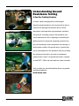
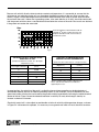
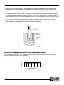
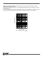
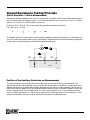
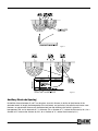
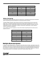
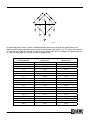
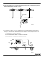
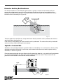
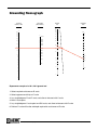
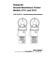
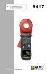
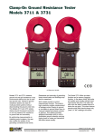
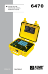
• Soil Resistivity • Ground Resistance • 3-Point Measurements • 4-Point Measurements • Clamp-On Measurements 200 Foxborough Blvd. • Foxborough, MA 02035 (800) 343-1391 • (508) 698-2115 FAX (508) 698-2118 • [email protected] www.aemc.com Understanding Ground Resistance Testing A One Day Training Seminar In today’s rapidly changing world of technological advances, good grounding is more important than ever to prevent costly damage and downtime due to service interruptions and inoperative surge protection caused by poor grounds. Grounding systems offer protection from natural phenomenon such as lightning by channeling the lightning current to the ground, protecting personnel from injury and protecting system components from damage. In electric power systems with ground returns, grounds help ensure rapid operation of the protection relays by providing low resistance fault paths in the event of unexpected potentials due to faults. Low ground resistance is required to meet NEC®, OSHA and other electrical safety standards. Visit us online for more information about our ground resistance seminars. www.aemc.com iv www.aemc.com Technical Assistance (800) 343-1391 Table of Contents Soil Resistivity ......................................................................................................................................... 2 Soil Resistivity Measurements (4-Point Measurement)............................................................................ 4 Grounding Electrodes............................................................................................................................... 5 Ground Resistance Testing Principle (Fall-of-Potential – 3-Point Measurement)................................................................................................. 9 Multiple Electrode Systems.................................................................................................................... 13 Tech Tips................................................................................................................................................ 15 Clamp-on Ground Resistance Measurement (Models 3711 and 3731)........................................................................................................................ 18 Telecommunications............................................................................................................................... 21 Grounding Nomograph........................................................................................................................... 24 Fall-of-Potential Plot............................................................................................................................... 25 ® AEMC Instruments Ground Testers....................................................................................................... 26 © 1999-2008 Chauvin Arnoux®, Inc. d.b.a. AEMC® Instruments Workbook Edition 10.0 950.WKBK-GROUND 09/08 Technical Assistance (800) 343-1391 www.aemc.com 1 Soil Resistivity Effects of Soil Resistivity on Grounding Electrode Resistance Soil resistivity is the key factor that determines what the resistance of a grounding electrode system will be, and to what depth it must be driven to obtain low ground resistance. The resistivity of the soil varies widely throughout the world and changes seasonally. Soil resistivity is determined largely by its content of electrolytes, which consist of moisture, minerals and dissolved salts. A dry soil has high resistivity if it contains no soluble salts. (Figure 1) Note:The lower the soil resistivity value, the lower the grounding electrode resistance will be. Resistivity (approx.), Ω-cm Average Max. Soil Min. Ashes, cinders, brine, waste 590 2370 7000 Clay, shale, gumbo, loam 340 4060 16,300 Same, with varying proportions of sand and gravel 1020 15,800 135,000 59,000 94,000 458,000 Gravel, sand, stones with little clay or loam Figure 1 Factors Affecting Soil Resistivity Two samples of soil, when thoroughly dried, may in fact become very good insulators having a resistivity in excess of 10 9 Ω-cm. The resistivity of the soil sample is seen to change quite rapidly until approximately 20% or greater moisture content is reached. (Figure 2) Moisture content % by weight Resistivity Ω-cm Top soil Sandy loam 0 >10 9 >10 9 2.5 250,000 150,000 5 165,000 43,000 10 53,000 18,500 15 19,000 10,500 20 12,000 6,300 30 6,400 4,200 Figure 2 The resistivity of the soil is also influenced by temperature. Figure 3 shows the variation of the resistivity of sandy loam, containing 15.2% moisture, with temperature changes from 20° to -15°C. In this temperature range the resistivity is seen to vary from 7200 to 330,000Ω-cm. Temperature °C 20 °F Resistivity Ω-cm 68 7200 10 50 9900 0 32 (water) 13,800 0 32 (ice) 30,000 -5 23 79,000 -15 14 330,000 Figure 3 2 www.aemc.com Technical Assistance (800) 343-1391 Because soil resistivity directly relates to moisture content and temperature, it is reasonable to assume that the resistance of any grounding system will vary throughout the different seasons of the year. Such variations are shown in Figure 4. Since both temperature and moisture content become more stable at greater distances below the surface of the earth, it follows that a grounding system, to be most effective at all times, should be constructed with the ground rod driven down a considerable distance below the surface of the earth. Best results are obtained if the ground rod reaches the water table. Ohms Seasonal variation of earth resistance with an electrode of 3/4" pipe in rather stony clay soil. Depth of electrode in earth is 3 ft for Curve 1, and 10 ft for Curve 2 Figure 4 THE EFFECT OF SALT* CONTENT ON THE RESISTIVITY OF SOIL (Sandy loam, Moisture content, 15% by weight, Temperature, 17°C) Added Salt (% by weight of moisture) Resistivity (Ω-cm) 0 10,700 0.1 1800 1.0 460 5 190 10 130 20 100 Figure 5 THE EFFECT OF TEMPERATURE ON THE RESISTIVITY OF SOIL CONTAINING SALT* (Sandy loam, 20% moisture. Salt 5% of weight of moisture) Temperature (Degrees C) Resistivity (Ω-cms) 20 110 10 142 0 190 -5 312 -13 1440 *Such as copper sulfate, sodium carbonate, and others. Salts must be EPA or local ordinance approved prior to use. Figure 6 In some locations, the resistivity of the earth is so high that low-resistance grounding can be obtained only at considerable expense and with an elaborate grounding system. In such situations, it may be economical to use a ground rod system of limited size and to reduce the ground resistivity by periodically increasing the soluble chemical content of the soil. Figure 5 shows the substantial reduction in resistivity of sandy loam brought about by an increase in chemical salt content. Chemically treated soil is also subject to considerable variation of resistivity with temperature changes, as shown in Figure 6. If salt treatment is employed, it is necessary to use ground rods which will resist chemical corrosion. Technical Assistance (800) 343-1391 www.aemc.com 3 Soil Resistivity Measurements (4-Point Measurement) Resistivity measurements are of two types; the 2-Point and the 4-Point method. The 2-Point method is simply the resistance measured between two points. For most applications the most accurate is the 4-Point method which is used in the Ground Tester Models 4610, 4620, 4630 or 6470. The 4-Point method (Figures 7 and 8), as the name implies, requires the insertion of four equally spaced and in-line electrodes into the test area. A known current from a constant current generator is passed between the outer electrodes. The potential drop (a function of the resistance) is then measured across the two inner electrodes. The Models 4610, 4620, 4630 and 6470 are calibrated to read directly in ohms. Where space or access to inserting rods is a problem, the Miller box may be used. The Schlumberger method is used mainly for geologic surveys. NOTE: To use feet instead of cm: 2π x (conversion from cm to ft) = (2) (3.14) (12) (2.54) = 191.5 Figure 7 A Z Y A Xv A A X A A B R A A A Figure 8 Where:A = distance between the electrodes in centimeters B = electrode depth in centimeters If A > 20 B, the formula becomes: ρ = 2π AR (with A in cm) ρ = 191.5 AR (with A in ft) ρ = Soil resistivity (Ω-cm) The value to be used for ρ is the average resistivity of the ground at a depth equivalent to the distance “A” between two electrodes for all tests taken. Given a sizable tract of land in which to determine the optimum soil resistivity some intuition is in order. Assuming that the objective is low resistivity, preference should be given to an area containing moist loam as opposed to a dry sandy area. Consideration must also be given to the depth at which resistivity is required. 4 www.aemc.com Technical Assistance (800) 343-1391 Example After inspection, the area investigated has been narrowed down to a plot of ground approximately 75 square feet (7m2). Assume that you need to determine the resistivity at a depth of 15 ft (450cm). The distance “A” between the electrodes must then be equivalent to the depth at which average resistivity is to be determined (15 ft, or 450cm). Using the more simplified Wenner formula (ρ = 2π AR), the electrode depth must then be no more than 1/20th of the electrode spacing or 8 ⅞" (22.5cm). Lay out the electrodes in a grid pattern and connect to the instrument as shown in Figure 8. Proceed as follows: • Remove the shorting link between X and Xv (C1, P1) • Connect all four auxiliary rods (Figure 7) For example, if the reading is R = 15 ρ (resistivity) = 2π x A x R A (distance between electrodes) = 450cm ρ = 6.28 x 15 x 450 = 42,390Ω-cm Grounding Electrodes The term “ground” is defined as a conducting connection by which a circuit or equipment is connected to the earth. The connection is used to establish and maintain as closely as possible the potential of the earth on the circuit or equipment connected to it. A “ground” consists of a grounding conductor, a bonding connector, its grounding electrode(s), and the soil in contact with the electrode. “Grounds” have several protection applications. For natural phenomena such as lightning, grounds are used to discharge the system of current before personnel can be injured or system components damaged. For foreign potentials due to faults in electric power systems with ground returns, grounds help ensure rapid operation of the protection relays by providing low resistance fault current paths. This provides for the removal of the foreign potential as quickly as possible. The ground should drain the foreign potential before personnel are injured and the power or communications system is damaged. Ideally, to maintain a reference potential for instrument safety, protect against static electricity, and limit the system to frame voltage for operator safety, a ground resistance should be zero ohms. In reality, as we describe further in the text, this value cannot be obtained. ® Last but not least, low ground resistance is essential to meet NEC , OSHA and other electrical safety standards. Figure 9 illustrates a grounding rod. The resistance of the electrode has the following components: (A) The resistance of the metal and that of the connection to it. (B) The contact resistance of the surrounding earth to the electrode. (C)The resistance in the surrounding earth to current flow or earth resistivity which is often the most significant factor. More specifically: (A) Grounding electrodes are usually made of a very conductive metal (copper or copper clad) with adequate cross sections so that the overallresistance is negligible. Technical Assistance (800) 343-1391 www.aemc.com 5 (B) The National Institute of Standards and Technology has demonstrated that the resistance between the electrode and the surrounding earth is negligible if the electrode is free of paint, grease, or other coating, and if the earth is firmly packed. (C) The only component remaining is the resistance of the surrounding earth. The electrode can be thought of as being surrounded by concentric shells of earth or soil, all of the same thickness. The closer the shell to the electrode, the smaller its surface; hence, the greater its resistance. The farther away the shells are from the electrode, the greater the surface of the shell; hence, the lower the resistance. Eventually, adding shells at a distance from the grounding electrode will no longer noticeably affect the overall earth resistance surrounding the electrode. The distance at which this effect occurs is referred to as the effective resistance area and is directly dependent on the depth of the grounding electrode. Ground rod and clamp Contact resistance between rod and soil Concentric shells of earth Figure 9 Effect of Grounding Electrode Size and Depth on Resistance Resistance in % Size: Increasing the diameter of the rod does not significantly reduce its resistance. Doubling the diameter reduces resistance by less than 10%. (Figure 10) 100 75 50 25 0 1/2 5/8 3/4 1 1 1/4 1 1/2 1 3/4 Rod diameter (inches) Figure 10 6 www.aemc.com Technical Assistance (800) 343-1391 Depth: As a ground rod is driven deeper into the earth, its resistance is substantially reduced. In general, doubling the rod length reduces the resistance by an additional 40% (Figure 11). The NEC (2008, 250.53 (G)) requires a minimum of 8 ft. (2.4m) in contact with the soil. NEC (2008, 250.52 (A)(5)(b)) states that rod electrodes of stainless steel and copper or zinc coated steel shall be at least 15.87mm (5/8 in) diameter, unless listed and not less than 12.70mm (1/2 in) in diameter. 200 100 Resistance in ohms 80 60 40 30 20 1" dia. 1/2" dia. 10 8 6 5 4 3 2 1 5 15 25 35 40 50 60 70 Driven depth in feet Ground resistance versus ground rod depth Figure 11 Technical Assistance (800) 343-1391 www.aemc.com 7 Ground Rod Resistance – Ohms Soil Resistivity (Ohm-centimeters) Rod Depth Feet Rod Diameter Inches D 100 90 80 R 100 K DIA 70 90 80 P 70 100000 60 7 50 6 5 40 50 50000 40000 40 4 30 30000 30 8 60 3 20000 15000 20 20 10000 15 15 5000 1 1.5 4000 10 3000 1 2000 3/4 10 9 8 7 5 5/8 4 1/2 1000 6 5 500 4 3 2 3 1/4 2 1 Figure 12 1 Grounding Nomograph 1. Select required resistance on R scale 2. Select apparent resistivity on P scale 3. Lay straightedge on R and P scale, and allow to intersect with K scale 4. Mark K scale point 5. Lay straightedge on K scale point & DIA scale, and allow to intersect with D scale 6. Point on D scale will be rod depth required for resistance on R scale 8 www.aemc.com Technical Assistance (800) 343-1391 Ground Resistance Testing Principle (Fall-of-Potential — 3-Point Measurement) The potential difference between rods X and Y is measured by a voltmeter, and the current flow between rods X and Z is measured by an ammeter. (Note: X, Y and Z may be referred to as X, P and C or H, S or E in a 3-Point tester or C1, P2 and C2 in a 4-Point tester.) (Figure 13) By Ohm’s Law E = RI or R = E/I, we may obtain the grounding electrode resistance R. If E = 20V and I = 1A, then R = E = ––– I 20 ––– 1 = 20Ω This method requires the service neutral and any other grounding system be disconnected. It is not necessary to carry out all the measurements when using a ground tester. The ground tester will measure directly by generating its own current and displaying the resistance of the grounding electrode. Current supply Ammeter (I) Voltmeter (E) Ground electrode under test X Auxiliary potential electrode Y Auxiliary current electrode Z R EARTH Figure 13 Position of the Auxiliary Electrodes on Measurements The goal in precisely measuring the resistance to ground is to place the auxiliary current electrode Z far enough from the grounding electrode under test so that the auxiliary potential electrode Y will be outside of the effective resistance areas of both the grounding electrode and the auxiliary current electrode. The best way to find out if the auxiliary potential rod Y is outside the effective resistance areas is to move it between X and Z and to take a reading at each location (See Figure 16). If the auxiliary potential rod Y is in an effective resistance area (or in both if they overlap, as in Figure 14), by displacing it the readings taken will vary noticeably in value. Under these conditions, no exact value for the resistance to ground may be determined. Technical Assistance (800) 343-1391 www.aemc.com 9 On the other hand, if the auxiliary potential rod Y is located outside of the effective resistance areas (Figure 15), as Y is moved back and forth the reading variation is minimal. The readings taken should be relatively close to each other, and are the best values for the resistance to ground of the grounding electrode X. The readings should be plotted to ensure that they lie in a “plateau” region as shown in Figure 15. The region is often referred to as the “62% area” (See page 11 for explanation). Readings every 5-10% of the distance from x to z are suggested. The average of the closest three readings (user defined) would be considered the resistance between earth and the test point. X Y' Y Y'' Z Resistance Effective resistance areas (overlapping) 52% 62% 72% (of total distance from X to Z) Reading variation 100% of distance between X & Z Figure 14 Resistance X Y' Y Y'' Effective resistance areas (no overlap) 52% 62% 72% (of total distance from X to Z) 100% of distance between X & Z 10 www.aemc.com Z Reading variation Figure 15 Technical Assistance (800) 343-1391 Measuring Resistance of Grounding Electrodes (62% Method) The 62% method has been adopted after graphical consideration and after actual test. It is the most accurate method but is limited by the fact that the ground tested is a single unit. This method applies only when all three electrodes are in a straight line and the ground is a single electrode, pipe, or plate, etc., as in Figure 16. Consider Figure 17, which shows the effective resistance areas (concentric shells) of the grounding electrode X and of the auxiliary current electrode Z. The resistance areas overlap. If readings were taken by moving the auxiliary potential electrode Y towards either X or Z, the reading differentials would be great and one could not obtain a reading within a reasonable band of tolerance. The sensitive areas overlap and act constantly to increase resistance as Y is moved away from X. Now consider Figure 18, where the X and Z electrodes are sufficiently spaced so that the areas of effective resistance do not overlap. If we plot the resistance measured we find that the measurements level off when Y is placed at 62% of the distance from X to Z, and that the readings on either side of the initial Y setting are most likely to be within the established tolerance band. This tolerance band is defined by the user and expressed as a percent of the initial reading: ±2%, ±5%, ±10%, etc. Disconnect Ground Rod from System Figure 16 Technical Assistance (800) 343-1391 www.aemc.com 11 Figure 17 Figure 18 Auxiliary Electrode Spacing No definite distance between X and Z can be given, since this distance is relative to the diameter of the electrode tested, its length, the homogeneity of the soil tested, and particularly, the effective resistance areas. However, an approximate distance may be determined from the following chart which is given for a homogeneous soil and an electrode of 1" in diameter. (For a diameter of ½", reduce the distance by 10%; for a diameter of 2" increase the distance by 10%; for a diameter of ⅜", reduce the distance by 8%.) 12 www.aemc.com Technical Assistance (800) 343-1391 Approximate distance to auxiliary electrodes using the 62% method Depth Driven Distance to Y Distance to Z 6 ft 45 ft 72 ft 8 ft 50 ft 80 ft 10 ft 55 ft 88 ft 12 ft 60 ft 96 ft 18 ft 71 ft 115 ft 20 ft 74 ft 120 ft 30 ft 86 ft 140 ft Multiple Rod Spacing Parallel multiple electrodes yield lower resistance to ground than a single electrode. High-capacity installations require low grounding resistance. Multiple rods are used to provide this resistance. A second rod does not provide a total resistance of half that of a single rod unless the two are several rod lengths apart. To achieve the grounding resistance place multiple rods one rod length apart in a line, circle, hollow triangle, or square. The equivalent resistance can be calculated by dividing by the number of rods and multiplying by the factor X (shown below). Additional considerations regarding step and touch potentials should be addressed by the geometry. Placing additional rods within the periphery of a shape will not reduce the grounding resistance below that of the peripheral rods alone. Multiplying Factors for Multiple Rods Number of Rods X 2 1.16 3 1.29 4 1.36 8 1.68 12 1.80 16 1.92 20 2.00 24 2.16 Multiple Electrode System A single driven grounding electrode is an economical and simple means of making a good ground system. But sometimes a single rod will not provide sufficient low resistance, and several grounding electrodes will be driven and connected in parallel by a cable. Very often when two, three or four grounding electrodes are being used, they are driven in a straight line; when four or more are being used, a hollow square configuration is used and the grounding electrodes are still connected in parallel and are equally spaced (Figure 19). Technical Assistance (800) 343-1391 www.aemc.com 13 a a a a DIAGONAL DIAGONAL Figure 19 In multiple electrode systems, the 62% method electrode spacing may no longer be applied directly. The distance of the auxiliary electrodes is now based on the maximum grid distance (i.e. in a square, the diagonal; in a line, the total length. For example, a square having a side of 20 ft will have a diagonal of approximately 28 ft). Three readings, minimum, are still required for proper testing. 14 Max Grid Distance Multiple Electrode System Distance to Y Distance to Z 6 ft 78 ft 125 ft 8 ft 87 ft 140 ft 10 ft 100 ft 160 ft 12 ft 105 ft 170 ft 14 ft 118 ft 190 ft 16 ft 124 ft 200 ft 18 ft 130 ft 210 ft 20 ft 136 ft 220 ft 30 ft 161 ft 260 ft 40 ft 186 ft 300 ft 50 ft 211 ft 340 ft 60 ft 230 ft 370 ft 80 ft 273 ft 440 ft 100 ft 310 ft 500 ft 120 ft 341 ft 550 ft 140 ft 372 ft 600 ft 160 ft 390 ft 630 ft 180 ft 434 ft 700 ft 200 ft 453 ft 730 ft www.aemc.com Technical Assistance (800) 343-1391 Tech Tips Excessive Noise Excessive noise may interfere with testing because of the long leads used to perform a Fall-of-Potential test. A voltmeter can be utilized to identify this problem. Connect the “X”, “Y” and “Z” cables to the auxiliary electrodes as for a standard ground resistance test. Use the voltmeter to test the voltage across terminals “X” and “Z ” (See Figure 20). Ground strip Y Electrode Z Electrode X Ground rod Figure 20 The voltage reading should be within stray voltage tolerances acceptable to your ground tester. If the voltage exceeds this value, try the following techniques: A) Braid the auxiliary cables together. This often has the effect of canceling out the common mode voltages between these two conductors. (Figure 21) Ground strip Y Electrode Z Electrode X Ground rod Figure 21 Technical Assistance (800) 343-1391 www.aemc.com 15 B) If the previous method fails, try changing the alignment of the auxiliary cables so that they are not parallel to power lines above or below the ground. (Figure 22) Disconnect ground under test Figure 22 C) If a satisfactory low voltage value is still not obtained, the use of shielded cables may be required. The shield acts to protect the inner conductor by capturing the voltage and draining it to ground. (Figure 23) 1. Float the shields at the auxiliary electrodes 2. Connect all three shields together at (but not to) the instrument 3. Solidly ground the remaining shield to the ground under test Ground shield Ground strip Float shield Float shield Connect all three shields together Y Electrode Z Electrode X Ground rod Figure 23 16 www.aemc.com Technical Assistance (800) 343-1391 Excessive Auxiliary Rod Resistance The inherent function of a Fall-of-Potential ground tester is to input a constant current into the earth and measure the voltage drop by means of auxiliary electrodes. Excessive resistance of one or both auxiliary electrodes can inhibit this function. This is caused by high soil resistivity or poor contact between the auxiliary electrode and the surrounding dirt (Figure 24). W er at Air gaps EARTH Figure 24 To ensure good contact with the earth, stamp down the soil directly around the auxiliary electrode to remove air gaps formed when inserting the rod. If soil resistivity is the problem, pour water around the auxiliary electrodes. This reduces the auxiliary electrode’s contact resistance without affecting the measurement. Asphalt or Concrete Mat Sometimes a test must be performed on a ground rod that is surrounded by a tar or concrete mat, where auxiliary electrodes cannot be driven easily. In such cases, metal screens and water can be used to replace auxiliary electrodes, as shown in Figure 25. Place the screens on the floor the same distance from the ground rod under test as you would auxiliary electrodes in a standard fall-of-potential test. Pour water on the screens and allow it to soak in. These screens will now perform the same function as would driven auxiliary electrodes. Ω Ground rod Water Screens Technical Assistance (800) 343-1391 Figure 25 www.aemc.com 17 Clamp-on Ground Resistance Measurement (Models 3711 & 3731) This measurement method is innovative and quite unique. It offers the ability to measure the resistance without disconnecting the ground. This type of measurement also offers the advantage of including the bonding to ground and the overall grounding connection resistances. This method requires connection of utility neutral or another grounding system so that the signal goes out to the other system and returns to the test point through the earth. Principle of Operation Usually, a common distribution line grounded system can be simulated as a simple basic circuit as shown in Figure 26 or an equivalent circuit, shown in Figure 30. If voltage E is applied to any measured grounding point Rx through a special transformer, current I flows through the circuit, thereby establishing the following equation. 1 1 E/I = Rx + –––––––––– where, usually Rx >> ––––––––––– n 1 n 1 –––– –––– ∑ Rk ∑ Rk k=1 k=1 Therefore, E/I = Rx is established. If I is detected with E kept constant, measured grounding point resistance can be obtained. Refer again to Figures 26 and 27. Current is fed to a special transformer via a power amplifier from a 2.4kHz constant voltage oscillator. This current is detected by a detection CT. Only the 2.4kHz signal frequency is amplified by a filter amplifier. This occurs before the A/D conversion and after synchronous rectification. It is then displayed on the LCD. The filter amplifier is used tocut off both earth current at commercial frequency and high-frequency noise. Voltage is detected by coils wound around the injection CT which is then amplified, rectified, and compared by a level comparator. If the clamp is not closed properly, an “open jaw” annunciator appears on the LCD. I E E I Rx Rx R1 R2 Rn-1 www.aemc.com R2 Rn-1 Rn Rn Figure 26 18 R1 Figure 27 Technical Assistance (800) 343-1391 Examples: Typical In-Field Measurements Pole Mounted Transformer Remove any molding covering the ground conductor, and provide sufficient room for the Model 3711 & 3731 jaws, which must be able to close easily around the conductor. The jaws can be placed around the ground rod itself. Note: The clamp must be placed so that the jaws are in an electrical path from the system neutral or ground wire to the ground rod or rods as the circuit provides. Select the current range “A.” Clamp onto the ground conductor and measure the ground current. The maximum current range is 30A. If the ground current exceeds 5A, ground resistance measurements are not possible. Do not proceed further with the measurement. Instead, remove the clamp-on tester from the circuit, noting the location for maintenance, and continue to the next test location. After noting the ground current, select the ground resistance range “Ω” and measure the resistance directly. The reading you measure with the Model 3711 & 3731 indicates the resistance not just of the rod, but also of the connection to the system neutral and all bonding connections between the neutral and the rod. Note that in Figure 28 there is both a butt plate and a ground rod. In this type of circuit, the instrument must be placed above the bond so that both grounds are included in the test. For future reference note the date, ohms reading, current reading and point number. Replace any molding you may have removed from the conductor. Note: A high reading indicates one or more of the following: A) Poor ground rod B) Open ground conductor C) High resistance bonds on the rod or splices on the conductor; watch for buried split bolts, clamps and hammer-on connections Signal return Figure 28 Technical Assistance (800) 343-1391 www.aemc.com 19 Service Entrance or Meter Follow basically the same procedure as in the first example. Notice that Figure 29 shows the possibility of multiple ground rods, and in Figure 30 the ground rods have been replaced with a water pipe ground. You may also have both types acting as a ground. In these cases, it is necessary to make the measurements between the service neutral and both grounded points. Signal out Signal return Figure 29 Signal out Signal return Figure 30 20 www.aemc.com Technical Assistance (800) 343-1391 Pad Mounted Transformer Note: Never open transformer enclosures. They are the property of the electrical utility. This test is for high voltage experts only. Observe all safety requirements, since dangerously high voltage is present. Locate and number all rods (usually only a single rod is present). If the ground rods are inside the enclosure, refer to Figure 31 and if they are outside the enclosure, refer to Figure 32. If a single rod is found within the enclosure, the measurement should be taken on the conductor just before the bond on the ground rod. Often, more than one ground conductor is tied to this clamp, looping back to the enclosure or neutral. In many cases, the best reading can be obtained by clamping the Models 3711 & 3731 onto the ground rod itself, below the point when the ground conductors are attached to the rod, so that you are measuring the ground circuit. Care must be taken to find a conductor with only one return path to the neutral. Signal out Signal return Figure 31 Telecommunications The clamp-on ground tester developed by AEMC® and discussed in the previous chapter has revolutionized the ability of power companies to measure their ground resistance values. This same proven instrument and technology can be applied to telephone industries to aid in detecting grounding and bonding problems. As equipment operates at lower voltages, the system’s ability to remove any man made or natural over potentials becomes even more critical. The traditional Fall-of-Potential tester proved to be labor intensive and left much to interpretation. Even more important, the clamp-on ground test method allows the user to make this necessary reading without the risky business of removing the ground under test from service. Signal out Underground service Signal return Technical Assistance (800) 343-1391 Figure 32 www.aemc.com 21 In many applications, the ground consists of bonding the two Utilities together to avoid any difference of potentials that could be dangerous to equipment and personnel alike. The clamp-on “Ohm meter” can be used to test these important bonds. Here are some of the solutions and clamp-on procedures that have applications to the telephone industry. Telephone Cabinets and Enclosures Grounding plays a very important role in the maintenance of sensitive equipment in telephone cabinets and enclosures. In order to protect this equipment, a low resistance path must be maintained in order for any overvoltage potentials to conduct safely to earth. This resistance test is performed by clamping a ground tester, Models 3711 and 3731, around the driven ground rod, below any common telephone and power company bond connections. To avoid any high voltage potentials between the telephone and power companies, a low resistance bond is established. Bonding integrity is performed by clamping around the No. 6 copper wire between the master ground bar (MGB) and the power company’s multigrounded neutral (MGN). The resistance value displayed on the tester will also include loose or poorly landed terminations that may have degraded over time. Additionally, the clamp-on ground tester can be used as a True RMS ammeter. Pedestal Grounds All cable sheaths are bonded to a ground bar inside each pedestal. This ground bar is connected to earth by means of a driven ground rod. The ground rod resistance can be found by using the instrument clamped around the ground rod or the No. 6 cable connecting these two points. (Figure 33) Signal return Signal out Figure 33 22 www.aemc.com Technical Assistance (800) 343-1391 Signal out WATT-hour meter Remote terminal cabinet Transfer switch Lightning arrester Power co. ground Ground rod (8 ft long) Telephone co. ground NOTE: If seperate ground rods are used for telephone and power grounds, the ground rods must be bonded together using no. 6 ground wire. Signal return Figure 34 Cable Shield Bonds to MGN The cable shields in a buried or above ground telephone enclosure may be grounded by means of the power company’s multigrounded neutral. The clamp-on ground tester can be utilized to ensure that this connection has been successfully terminated. The low resistance return path for the instrument to make this measurement will be from this bond wire under test to the MGN back through all other bonds up and/or down stream (theory of parallel resistance). The clamp-on ground tester also is a True RMS ammeter. Phone pedestal Ground bar Sheath connection Ground level Signal out Ground rod Signal return Note: temporary jumper required only if pedestal does not allow tester to fit. Figure 35 Technical Assistance (800) 343-1391 www.aemc.com 23 References IEEE Std 81-1983 — EEE Guide for Measuring Earth Resistivity, Ground Impedance, and Earth Surface Potentials of Ground Systems IEEE Std 142-1991 — IEEE Recommended Practice for Grounding of Industrial and Commercial Power Systems Blackburn/American Electric Co. Memphis, TN 38119 — A Modern Approach to Grounding Systems NEC 2008 — NFPA 24 www.aemc.com Technical Assistance (800) 343-1391 Grounding Nomograph Ground Rod Resistance – Ohms Soil Resistivity (Ohm-centimeters) Rod Depth Feet Rod Diameter Inches D 100 90 80 R 100 K 70 90 80 P 70 100000 60 50000 40000 40 7 6 5 4 30 30000 30 8 50 40 50 DIA 60 3 20000 15000 20 20 10000 15 15 5000 1 1.5 4000 10 3000 1 2000 3/4 10 9 8 7 5 5/8 4 1/2 1000 6 5 500 4 3 2 3 1/4 2 1 1 Represents example of a 20Ω, 20 ft ground rod 1.Select required resistance on R scale 2. Select apparent resistivity on P scale 3.Lay straightedge on R and P scale, and allow to intersect with K scale 4.Mark K scale point 5.Lay straightedge on K scale point and DIA scale, and allow to intersect with D scale 6.Point on D scale will be the rod depth required for resistance on R scale Technical Assistance (800) 343-1391 www.aemc.com 25 Fall-of-Potential Plot Instrument Mfr._____________ Name of Operator������������������������������������������������������ Model_____________ Location___________________________________ Date����������������������� Ground System Type:Single Rod n Rod Depth��������������������� ft Serial #_____________ Multiple Rods (Grid) n Longest Diagonal Dimension������� ft Z Electrode Distance�������������������������������������������������� ft Voltage Electrode (Y) Measured distance from Ground Resistance Rod under Test (X) % FEET Test Conditions Temp: ___________ Soil: n Moist n Dry Soil Type OHMS 100 n Loam n Sand & Gravel n Shale n Sandstone n Granite n Slate n Clay n Limestone n Other_ ____________ 50 100 90 45 90 80 40 80 72 70 35 70 62 30 60 Resistance (Ω) 60 52 50 25 50 20 40 40 15 30 30 20 10 20 10 5 10 0 0 0 Resistance Scale: Multiplier: 26 www.aemc.com 50 100 x1 x10 0 10 20 30 40 50 60 70 80 Distance in Feet from Ground under Test to Voltage Electrode (Y) Distance Scale Multiplier: x1 x10 Disconnect Ground Rod from System Technical Assistance (800) 343-1391 90 100 Ground resistance testers Multi-Function Ground Resistance Tester Model 6472 NEW! Model 6472 Specifications MODEL 6472 electrical 3-Point Measurement Range (Auto-Ranging) Resolution Test Voltage Resistance Measurement Frequency Test Current Accuracy Soil Resistivity 4-Point Measurement Test Method Range (Auto-Ranging) Resolution Test Voltage Frequency External Voltage Measurement Range (Auto-Ranging) Accuracy Resistance Measurement (Bond Testing) Measurement Type Range (Auto-Ranging) Accuracy Test Voltage Test Current Data Storage Memory Capacity Communication Power Source Recharging Source 18 www.aemc.com 0.09Ω to 99.9kΩ 0.01Ω to 100Ω Nominal 16 or 32VRMS user selectable 41 to 5078Hz user selectable or automatic selection Up to 250mA ±2% of Reading + 1ct @ 128Hz Wenner or Schlumberger selectable with automatic calculation of test results in Ω-meters, Ω-cm or Ω-feet 0.01 to 99.99kΩ; ρ Max: 999kΩm (display in kΩft is not possible) 0.01 to 100Ω 16 or 32V user selectable From 41 to 128Hz selectable 0.1 to 65.0Vac/dc – DC to 440Hz ±2% of Reading + 1cts 2-Pole (with lead resistance compensation) or 4-Pole (Kelvin sensing) user selectable 2-Pole 0.01Ω to 99.9kΩ; 4-Pole 0.001Ω to 99.99kΩ ±2% of Reading + 2cts 16Vdc (+, - or auto polarity) Up to 250mA max 512 test results Optically Isolated USB 9.6V rechargeable battery pack 110/220 50/60Hz external charger with 18Vdc, 1.9A output or 12V vehicle power Features •2- and 4-Wire Bond Resistance/Continuity Measurement (DC Resistance) with automatic polarity reversal •3-Point Fall-of-Potential measurement with manual or automatic frequency selection •4-Point soil resistivity measurement with automatic calculation of Rho (ρ) and user selection of the Wenner or Schlumberger test method •3-Point earth coupling measurement •Measures Ground Resistance using the 2 clamp method (selective ground testing) •Measures Ground Impedance at frequencies up to 5kHz to test lightning strike protection •Manual and automatic frequency scan from 40 to 5078Hz for optimum test accuracy in electrically noisy environments •Selectable test voltage of 16 or 32V up to 250mA of test current •Auto-off power management •Automatic recognition of all electrode connections and their resistance value •Stores up to 512 complete test results • Optically isolated USB communication •Remote set up and operation of all measurements using DataView® software •Automatic report generation including the fall of potential plot •Rechargeable NiMH batteries from wall charger or vehicle power •Rugged dustproof and rainproof field case •Includes DataView® software for data storage, real-time display, analysis, report generation and system configuration Description The Model 6472 measures from 0.01 to 99.99kΩ and is auto-ranging, automatically seeking out the optimum measurement range, test frequency and test current. Easy-to-use – Simply connect the leads, select test mode, press Start and read the results. Up to 512 test results can be stored in internal memory for recall to the display or downloaded to a PC via DataView® software. The large LCD is easy-to-read and indicates ground electrode resistance, test voltage, current and frequency as well as individual electrode resistance, battery status and more. The Model 6472 is Cat IV rated to 50V and is over voltage protected to more than 250Vac against accidental live connection to live circuits. The voltage is also displayed on screen. In the event of a system fault, the Model 6472 can withstand 250Vac. Additional features of the Model 6472 include; manual and automatic test frequency selection from 40 to 5078Hz; user selectable 3 or 4-Pole Fall of Potential or 4-Pole Soil Resistivity test methods and user selectable 2-Wire or 4-Wire Bond Resistance test method. The Model 6472 is powered by 9.6V, 3.5 Ah NiMH rechargeable batteries. An external recharger powered from 120/230V, 50/60Hz is included and provides for testing while recharging. The Model 6472 can also be vehicle powered from an optional 12V battery adapter. (Cat. #2135.42) Technical Assistance (800) 343-1391 Ground resistance testers Large Display! 4-Point Bond Test 3-Point Fall-of-Potential Test DataView ® Software for Model 6472 DataView ® is included with the Model 6472. The 4-Point Bond test displaying lead connections, bond resistance test results, test voltage and current. The 3-Point Fall-of-Potential test displaying test lead connection, grounding electrode resistance, test voltage and frequency. Frequency Selection Test Data Storage The Frequency selection screen displays selected test frequency and voltage for the test as well as lead connection. Memory Recall displays test results stored at a specific memory location. Schlumberger Test Wenner Test The Schlumberger test displays test lead connection, soil resistivity ( ) test results, test electrode resistance and more. ρ The Wenner test displays test lead connection, soil resistivity ( ) test results, electrode spacing and resistance. ρ NOTE: More information for each test is available by scrolling through the displays. Current Probe accessory options (For use in two probe and selective ground testing methods) AC Current Probe Model MN82 AC Current Probe Model SR182 Catalog #2135.71 Catalog #2135.72 Catalog No. • Configure all functions and parameters from your PC • Display and analyze real-time data on your PC • Customize views, templates and reports to your exact needs • Create and store a complete library of configurations that can be uploaded to the Model 6472 as needed • Zoom in and out and pan through sections of the graph to analyze the data • Download, display and analyze recorded data • Print reports using standard or custom templates you design Includes meter, rechargeable NiMH batteries, optical USB cable, power adapter 110/240V with power cord 115V US, two 500 ft color-coded leads on spools (red/blue), two 100 ft color-coded leads (hand-tied, green/black), one 30 ft lead (green), four T-shaped auxiliary ground electrodes, set of five spaded lugs, one 100 ft AEMC® tape measure, DataView® software, ground tester workbook CD, carrying bag for meter, carrying bag for kit, product warranty and registration card and a user manual. Catalog #2135.54 Description Ground Resistance Tester Model 6472 (2-Point, 3-Point, 4-Point, Bond Test, Digital, 2135.51 Rechargeable Battery, DataView® software) 2135.52 Ground Resistance Tester Model 6472 Kit – 150 ft (Model 6472 and Catalog #2135.35) 2135.53 Ground Resistance Tester Model 6472 Kit – 300 ft (Model 6472 and Catalog #2135.36) 2135.54 Ground Resistance Tester Model 6472 Kit – 500 ft (Model 6472 and Catalog #2135.37) Accessories (Optional) Reference to page 21 for Model 6472 Kits Catalog #2135.35, #2135.36 & #2135.37 2135.71* AC Current Probe Model MN82 for use with Model 6472 2135.72* AC Current Probe Model SR182 for use with Model 6472 *2 probes required for two clamp testing method. Technical Assistance (800) 343-1391 PRICE NIST CALIBRATION $3,795.00 $94.00 $4,195.00 $4,295.00 $4,395.00 $99.00 $99.00 $99.00 $ 299.00 $ 369.00 – – www.aemc.com 19 Ground resistance testers Multi-Function Ground Resistance Tester Model 6470 Features Measure ground resistance, soil resistivity and bonding resistance with one instrument! Model 6470 Specifications MODEL 6470 electrical 3-Point Measurement Range (Auto-Ranging) Resolution Test Voltage Resistance Measurement Frequency Test Current Accuracy Soil Resistivity 4-Point Measurement Test Method Range (Auto-Ranging) Resolution Test Voltage Frequency External Voltage Measurement Range (Auto-Ranging) Accuracy Resistance Measurement (Bond Testing) Measurement Type Range (Auto-Ranging) Accuracy Test Voltage Test Current Data Storage Memory Capacity Communication Power Source Recharging Source 20 www.aemc.com 0.01 to 99.99kΩ 0.01 to 100Ω 16 or 32V selectable 40 to 513Hz selectable or automatic selection Up to 250mA ±2% of Reading + 1ct Wenner or Schlumberger selectable with automatic calculation of test results displayed in Ω-meters or Ω-feet 0.01 to 99.99kΩ 0.01 to 100Ω 16 or 32V selectable 73, 91.5, 101, 110 or 128Hz selectable •3- and 4-Point measurement with manual or automatic frequency selection (even during measurement) from 40 up to 500Hz •Automatic calculation of Soil Resistivity Ωcm •Selectable test voltage of 16 or 32V with up to 250mA •Automatic frequency scan for optimum test frequency in noisy environments •Automatic measurement of auxiliary electrodes resistance •Soil resistivity measurement using Wenner or Schlumberger test method • 2- and 4-Point DC resistance measurement with automatic polarity change (Bonding test function) •Auto-off power management •Automatic recognition of all electrode connections and their resistance value •Memory stores up to 512 test results •USB communication •Remote operation of all measurement functions using DataView ® software •Automatic report generation through computer or serial printer •Rechargeable NiMH battery pack •Rugged dustproof and rainproof field case IP54 in closed position •IEC 61557 part 4 and part 5 compliance •Includes DataView ® software for data storage, real-time display, analysis report generation and system configuration Model 6470 includes meter, NiMH batteries, optical USB cable, DataView ® software, external battery charger, power cord 110/240V (line) and user manual. 0.1 to 65.0Vac/dc – DC to 450Hz 2% of Reading + 2cts 2-Point or 4-Point user selectable 2-Point 0.01 to 99.9kΩ; 4-Point 0.001 to 99.99kΩ ±2% of Reading + 2cts 16Vdc 200mA max 512 test results Optically isolated USB 9.6V NiMH rechargeable battery pack 110/120 50/60Hz external charge with 18VDC, 1.9A output or 12VDC vehicle power Technical Assistance (800) 343-1391 Ground resistance testers Large Display! 4-Point Bond Test 3-Point Fall-of-Potential Test DataView ® Software for Model 6470 DataView ® is included with the Model 6470. The 4-Point Bond test shows lead connections, bond resistance test results, test voltage and current. The 3-Point Fall-of-Potential test displays test lead connection, grounding rod resistance and test electrode resistances. Frequency Test Memory Test The Frequency selection screen displays selected test frequency and voltage for the test as well as lead connection. Displays test results stored at a specific memory location as well as the test function. Schlumberger Test Wenner Test The Schlumberger test displays test lead connection, soil resistivity ( ) test results and electrode spacing. ρ Catalog No. 2135.01 2135.02 2135.03 2135.04 Accessories (Optional) The Wenner test displays test lead connection, soil resistivity ( ) test results, electrode spacing and resistance. ρ •Configure all functions and parameters from your PC • Display and analyze real-time data on your PC •Customize views, templates and reports to your exact needs •Create and store a complete library of configurations that can be uploaded to the Model 6470 as needed • Zoom in and out and pan through sections of the graph to analyze the data •Download, display and analyze recorded data •Print reports using standard or custom templates you design Multi-Function Ground Resistance Tester Model 6470 Kit (500 ft) includes meter, NiMH batteries, optical USB cable, DataView ® software, external battery charger, power cord 110/240V (line), one 30 ft green wire, one each 500 ft red and blue wire, one each 100 ft black and green wire, set of five spaded lugs, four auxiliary ground electrodes, tape measure, carrying case and user manual. Catalog #2135.04 Description Ground Resistance Tester Model 6470 (2-Point, 3-Point, 4-Point, Bond Test, Digital, Rechargeable Battery, DataView® software) Ground Resistance Tester Model 6470 Kit – 150 ft (Model 6470 and Catalog #2135.35) Ground Resistance Tester Model 6470 Kit – 300 ft (Model 6470 and Catalog #2135.36) Ground Resistance Tester Model 6470 Kit – 500 ft (Model 6470 and Catalog #2135.37) PRICE NIST CALIBRATION $2,250.00 $94.00 $2,649.00 $2,749.00 $2,849.00 $99.00 $99.00 $99.00 2135.35 Test Kit for 3-Point testing (includes two 150 ft color-coded leads on spools (red/blue), one 30 ft lead (green), two 14.5" T-shaped auxiliary ground electrodes, set of five spaded lugs, 100 ft tape measure and soft carrying bag) $ 449.00 – 2135.36 Test Kit for 4-Point testing (includes two 300 ft color-coded leads on spools (red/blue), two 100 ft color-coded leads (hand-tied green/black), four 14.5" T-shaped auxiliary ground electrodes, set of five spaded lugs, 100 ft tape measure and soft carrying bag) $ 549.00 – 2135.37 Test Kit for 4-Point testing (includes two 500 ft color-coded leads on spools (red/blue), two 100 ft color-coded leads (hand-tied green/black), one 30 ft lead (green), four 14.5" T-shaped auxiliary ground electrodes, set of five spaded lugs, 100 ft tape measure and soft carrying bag) $ 649.00 – 2135.38 Ground Test Kit for 3-Point testing (Supplemental for 4-Point testing – includes two 100 ft color-coded leads (hand-tied green/black), one 30 ft lead (green), two 14.5" T-shaped auxiliary ground electrodes and soft carrying bag) $ 249.00 – Technical Assistance (800) 343-1391 www.aemc.com 21 Ground resistance testers Ground Resistance Tester Models 4620 & 4630 Model 4630 Specifications MODELS 4620 4630 electrical 20Ω 200Ω 2000Ω Range Measurement Range 0.00 to 19.99Ω 20.0 to 199.9Ω 200 to 1999Ω Resolution 10mΩ 100mΩ 1Ω Open Voltage ≤42V peak ≤42V peak ≤42V peak Resistance Measurement 128Hz square wave 128Hz square wave 128Hz square wave Frequency Test Current 10mA 1mA 0.1mA Accuracy ±2% of Reading ± 1ct ±2% of Reading ± 1ct ±2% of Reading ± 3ct Auxiliary Electrode Influence Max Res. in Current Circuit 50kΩ 30kΩ 3kΩ Max Res. in Voltage Circuit 50kΩ 50kΩ 50kΩ Response Time Approximately four to eight seconds for a stabilized measurement Withstanding Voltage 250Vac or 100Vdc Power Source Eight C cell batteries; 120/230V 50/60Hz Alkaline recommended Rechargeable 9.6V, 3.5 Ah NiMH battery pack Battery Life >2000 15-second measurements; LO BAT indication on LCD Fuse Protection 0.1A, >250V, 0.25 x 1.25"; 30kA Interrupt Capacity Catalog No. Features •Measures soil resistivity (4-Point) •Measures ground resistance (2- and 3-Point) Fall-of-Potential method •Step voltage tests and touch potential measurements •Auto-Ranging: automatically selects the optimum resistance range and test current •Designed to reject high levels of noise and interference •Extremely simple to operate: connect - press - read •LED on faceplate informs operator of high input noise, high auxiliary rod resistance and fault connections • Large easy-to-read backlit display •Battery powered (Model 4620) •AC powered with rechargeable NiMH b attery pack (Model 4630) •Rugged dustproof and rainproof field case •Can also be used for continuity tests on bonding • Color-coded terminals Test Kit for 3-Point testing includes two 150 ft color-coded leads on spools (red and blue), one 30 ft lead (green), two 14.5" T-shaped auxiliary ground electrodes, one set of five spaded lugs, 100 ft tape measurer and carrying bag. Catalog #2135.35 Test Kit for 4-Point testing includes two 300 ft color-coded leads on spools (red and blue), two 100 ft color-coded leads (green and black), four 14.5" T-shaped auxiliary ground e lectrodes, one set of five spaded lugs, 100 ft tape measurer and carrying bag. Catalog #2135.36 Test Kit for 4-Point testing includes two 500 ft color-coded leads on spools (red and blue), two 100 ft color-coded leads (green and black), one 30 ft lead (green), four 14.5" T-shaped auxiliary ground electrodes, one set of five spaded lugs, 100 ft tape m easurer and carrying bag. Catalog #2135.37 See page 23 for Ground Testing kit images. Description 2130.43 Ground Resistance Tester Model 4620 (Digital, 4-Point, Battery Powered) 2130.44 Ground Resistance Tester Model 4630 (Digital, 4-Point, Rechargeable Battery) 2135.19 Ground Resistance Tester Model 4620 Kit – 150 ft (Model 4620 and Catalog #2135.35) 2135.20 Ground Resistance Tester Model 4620 Kit – 300 ft (Model 4620 and Catalog #2135.36) 2135.21 Ground Resistance Tester Model 4620 Kit – 500 ft (Model 4620 and Catalog #2135.37) 2135.22 Ground Resistance Tester Model 4630 Kit – 150 ft (Model 4630 and Catalog #2135.35) 2135.23 Ground Resistance Tester Model 4630 Kit – 300 ft (Model 4630 and Catalog #2135.36) 2135.24 Ground Resistance Tester Model 4630 Kit – 500 ft (Model 4630 and Catalog #2135.37) Accessories (Optional) 2130.60 Tape Measure (100 ft) 2135.35 Test Kit for 3-Point testing – 150 ft (see descriptions above for details) 2135.36 Test Kit for 4-Point testing – 300 ft (see descriptions above for details) 2135.37 Test Kit for 4-Point testing – 500 ft (see descriptions above for details) Ground Test Kit for 3-Point testing (Supplemental for 4-Point testing – includes two 100 ft 2135.38 color-coded leads, one 30 ft lead (green), two 14.5" T-shaped auxiliary ground electrodes and soft carrying bag) (see descriptions above) 2130.59 Calibration checker – 25Ω for Models 3620, 3640, 4500, 4610, 4620 and 4630 22 www.aemc.com PRICE NIST CALIBRATION $1,265.00 $1,795.00 $1,669.00 $1,769.00 $1,869.00 $2,199.00 $2,299.00 $2,399.00 $ 94.00 $ 94.00 $105.00 $105.00 $105.00 $105.00 $105.00 $105.00 $ 34.95 $ 449.00 $ 549.00 $ 649.00 – – – – $ 249.00 – $ – 54.95 Technical Assistance (800) 343-1391 Ground resistance testers Ground Resistance Tester Models 3620, 3640 & 4610 Features •Measures soil resistivity (4-Point) (Model 4610) •Measures ground resistance (2- and 3-Point) Fall-of-Potential method •Large analog display (Model 3620) •Large LCD digital display (Models 3640 and 4610) •Designed to reject high levels of noise and interference •Auto-Ranging: automatically selects the optimum range (Models 3640 and 4610) • Battery powered •Extremely simple to operate: connect - press- read • Error indicator lights • Rugged dustproof and rainproof case •Color-coded terminals and lead identification See page 22 for Ground Testing kit descriptions. Catalog #2135.35 Model 4610 All individual units include soft carrying case and user manual. Specifications MODELS Types of Measurements Display Soil Resistivity Test Measurement Ranges 3620 2- and 3-Point Analog No 0.5 to 1000Ω Resolution Test Current Catalog #2135.36 Open Voltage Operating Frequency Accuracy Interference Power Source Battery Life Low Battery Indication Fuse Protection Catalog #2135.37 – 10mΩ 100mΩ 1Ω 10mA 10mA 1mA 0.1mA ≤24V peak ≤42V peak 128Hz square wave ±5% of Reading + 0.1% ±2% of Reading ± 1ct ±3% of Reading ± 3cts scale length All models reject high levels of interference voltage (DC, 50 to 60Hz, harmonics) Eight 1.5V AA batteries Approx. 1680 15-second Approx. 1800 15-second measurements measurements Yes High breaking capacity, 0.1A, >250V Catalog No. Description 2114.90 2114.92 2114.94 2135.10 2135.11 2135.12 2135.13 2135.14 2135.15 2135.16 2135.17 2135.18 2130.59 Ground Resistance Tester Model 3620 (Analog, 3-Point) Ground Resistance Tester Model 3640 (Digital, 3-Point) Ground Resistance Tester Model 4610 (Digital, 4-Point) Ground Resistance Tester Model 3620 Kit – 150 ft (Model 3620 and Catalog #2135.35) Ground Resistance Tester Model 3620 Kit – 300 ft (Model 3620 and Catalog #2135.36) Ground Resistance Tester Model 3620 Kit – 500 ft (Model 3620 and Catalog #2135.37) Ground Resistance Tester Model 3640 Kit – 150 ft (Model 3640 and Catalog #2135.35) Ground Resistance Tester Model 3640 Kit – 300 ft (Model 3640 and Catalog #2135.36) Ground Resistance Tester Model 3640 Kit – 500 ft (Model 3640 and Catalog #2135.37) Ground Resistance Tester Model 4610 Kit – 150 ft (Model 4610 and Catalog #2135.35) Ground Resistance Tester Model 4610 Kit – 300 ft (Model 4610 and Catalog #2135.36) Ground Resistance Tester Model 4610 Kit – 500 ft (Model 4610 and Catalog #2135.37) Calibration checker – 25Ω for Models 3620, 3640, 4500, 4610, 4620 and 4630 Technical Assistance (800) 343-1391 3640 4610 2- and 3-Point 2-, 3-, and 4-Point Digital Digital No Yes 20Ω: 200Ω: 2000Ω: 0.00 to 19.99Ω 20.0 to 199Ω 200 to 1999Ω PRICE NIST CALIBRATION $ 759.00 $ 795.00 $1,045.00 $1,159.00 $1,259.00 $1,359.00 $1,175.00 $1,275.00 $1,375.00 $1,449.00 $1,549.00 $1,649.00 $ 54.95 $ 94.00 $ 94.00 $ 94.00 $105.00 $105.00 $105.00 $105.00 $105.00 $105.00 $105.00 $105.00 $105.00 – www.aemc.com 23 Ground resistance testers Clamp-On Ground Resistance Tester Models 3711 & 3731 Features •Simple and fast clamp-on operation no leads, no auxiliary rods or spacing requirements •Direct reading of ground resistance from 0.1 to 1200Ω •Direct reading of continuity and ground loop resistance •Direct reading of ground leakage or phase current from 1mA to 30Arms •Jaw design with large 1.25" (32mm) window accommodates up to 1000kcmil cables • Auto-Off for power management •Alarm function with adjustable set point and buzzer for quick field checks (Model 3731) •Memory function to store 99 field measurements for later retrieval and analysis (Model 3731) •Rugged Lexan® head and body construction resists breakage •Alarm settings and stored memory information saved during shutdown (Model 3731) •Designed to EN 61010-1, Cat. III safety standards • Patented design Model 3731 US Patent No. 362,639 FEATURES & FUNCTIONS Specifications MODELS 3711 & 3731 electrical Measurement Range 0.1 to 1.0Ω 1.0 to 50.00Ω 50.0 to 100.0Ω 100 to 200Ω 200 to 400Ω 400 to 600Ω 600 to 1200Ω Resolution Accuracy (% of Reading) 0.01Ω 0.1Ω 0.5Ω 1Ω 5Ω 10Ω 50Ω ±(2% ± 0.02Ω) ±(1.5% ± 0.1Ω) ±(2.0% ± 0.5Ω) ±(3.0% ± 1Ω) ±(6% ± 5Ω) ±(10% ± 10Ω) 25% of Reading ±50Ω 1 to 299mA 1mA ±(2.5% + 2mA) 0.300 to 2.999A 0.001A ±(2.5% + 2mA) 3.00 to 29.99A 0.01A ±(2.5% + 20mA) Ground Resistance Auto-Ranging 0.01 to 1200Ω Current Measurement Auto-Ranging 1mA to 30.00Arms Resistance Measurement Frequency 47 to 800Hz OL displayed above 29.99Arms 9V Alkaline battery; Battery life: Eight hours or approximately 1000 measurements of 30 seconds Description 2117.60 2117.61 Ground Resistance Tester Model 3711 (Clamp-On) Ground Resistance Tester Model 3731 (Clamp-On with memory and alarm) www.aemc.com 3731 3 3 3 3 3 3 3 3 3 3 3 3 3 3 3 3 3 3 3 3 3 3 – – Models 3711 and 3731 include calibration loop, battery, hard carrying case and user manual. Catalog No. 24 3711 2403Hz Current Measurement Frequency Current Overload Power Source MODELS Ohms Range Arms Range Hold Function Self Test Auto-Off Battery Life Indicator Noise Indicator Open Jaw Indicator Closed Loop Indicator Multi-Tone Beeper Alarm Function Memory (Logging) PRICE NIST CALIBRATION $1,545.00 $1,745.00 $ 98.00 $ 98.00 Technical Assistance (800) 343-1391 Chauvin Arnoux®, Inc. d.b.a. AEMC® Instruments 200 Foxborough Blvd. • Foxborough, MA 02035 • USA (508) 698-2115 • (800) 343-1391 • Fax (508) 698-2118 [email protected] • www.aemc.com