1
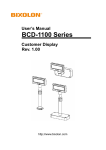
P07303 Series Customer Display
User Manual
2006 July V1.6
Copyright 2006’ 06
All Rights Reserved
Manual Version 1.6
The information contained in this document is subject to change without notice.
We make no warranty of any kind with regard to this material, including, but not
limited to, the implied warranties of merchantability and fitness for a particular
purpose. We shall not be liable for errors contained herein or for incidental or
consequential damages in connection with the furnishing, performance, or use of
this material.
This document contains proprietary information that is protected by copyright. All
rights are reserved. No part of this document may be photocopied, reproduced or
translated to another language without the prior written consent of the
manufacturer.
General Notice: All the company names used herein are for identification
purposes only and may be trademarks of their respective companies.
Safety
IMPORTANT SAFETY INSTRUCTIONS
1. To disconnect the machine from the electrial power supply, turn off the power
switch and remove the power cord plug from the wall socket. The wall socket
must be easily accessible and in close proximity to the machine.
2. Read these instructions carefully. Save these instructions for future reference.
3. Follow all warnings and instructions marked on the product.
4. Do not use this product near water.
5. Do not place this product on an unstable cart,stand,or table.The product may
fall, causing serious damage to the product.
6. Slots and openings in the cabinet and the back or bottom are provided for
ventilation;to ensure reliable operation of the product and to protect it from
overheating. These openings must not be blocked or covered.The openings
should never be blocked by placing the product on a bed, sofa, rug, or other
similar surface.This product should never be placed near or over a radiator or
heat register,or in a built-in installation unless proper ventilation is provided.
7. This product should be operated from the type of power indicated on the
marking label.If you are not sure of the type of power available, consult your
dealer or local power company.
8. Do not allow anything to rest on the power cord. Do not locate this product
where persons will walk on the cord.
9. Never push objects of any kind into this product through cabinet slots as they
may touch dangerous voltage points or short out parts that could result in a fire
or electric shock.Never spill liquid of any kind on the product.
FCC
This device complies with part 15 of the FCC rules. Operation is subject to the
following two conditions:
(1) This device may not cause harmful interference
(2) This device must accept any interference received, including interference that
may cause undesired operation.
CE Mark
This device complies with the requirements of the EEC directive
89/336/EEC with regard to “Electromagnetic compatibility” and
73/23/EEC “Low Voltage Directive”.
LEGISLATION AND WEEE SYMBOL
2002/96/EC Waste Electrical and Electronic Equipment Directive on the
treatment, collection, recycling and disposal of electric and electronic
devices and their components.
The crossed dustbin symbol on the device means that it should not be disposed of
with other household wastes at the end of its working life. Instead, the device
should be taken to the waste collection centers for activation of the treatment,
collection, recycling and disposal procedure.
To prevent possible harm to the environment or human health from uncontrolled
waste disposal, please separate this from other types of wastes and recycle it
responsibly to promote the sustainable reuse of material resources.
Household users should contact either the retailer where they purchased this
product, or their local government office, for details of where and how they can
take this item for environmentally safe recycling.
Business users should contact their supplier and check the terms and conditions
of the purchase contract.
This product should not be mixed with other commercial wastes for disposal.
Table of Contents
A. 2 X 20 CUSTOMER DISPLAY
1.
CHECKLIST......................................................................................................... 7
2.
FEATURES .......................................................................................................... 7
3.
SPECIFICATION.................................................................................................. 8
4.
INTERFACE......................................................................................................... 9
4.1.
4.2.
4.3.
5.
SPECIFICATION ................................................................................................ 9
DISPLAY BASE................................................................................................. 9
CONNECTOR ................................................................................................... 9
DIP SWITCH AND SOFTWARE SETTING ........................................................ 11
5.1.
5.2.
5.3.
5.4.
5.5.
5.6.
6.
COMMAND TYPE SELECTION .......................................................................... 11
BAUD RATE SELECTION ................................................................................. 11
PARITY CHECK SELECTION ............................................................................. 11
DEMO MODE SELECTION ............................................................................... 11
INTERNATIONAL CHARACTER SET ................................................................... 12
COMMAND CONTROL ..................................................................................... 12
SOFTWARE STATUS SETTING COMMANDS ................................................. 13
6.1.
6.2.
6.3.
6.4.
6.5.
BAUD RATE SETTING COMMAND ..................................................................... 13
PARITY CHECK SETTING COMMAND ................................................................ 13
INTERNATIONAL CHARACTER SET SETTING COMMAND ...................................... 14
COMMAND TYPE SETTING COMMAND .............................................................. 15
SHOW FIRMWARE VERSION ............................................................................ 15
7.
COMMAND LIST TABLE ................................................................................... 16
8.
COMMAND DETAILS ........................................................................................ 18
8.1.
8.2.
8.3.
8.4.
8.5.
8.6.
8.7.
8.8.
9.
POS7300 SERIES COMMAND LIST ................................................................. 18
CD5220 STANDARD MODE COMMAND LIST..................................................... 19
UTC STANDARD MODE COMMAND LIST .......................................................... 21
UTC ENHANCED MODE COMMAND LIST .......................................................... 21
AEDEX/EMAX MODE COMMAND LIST ........................................................... 22
ADM787/788 MODE COMMAND LIST ............................................................... 22
DSP800 MODE COMMAND LIST ..................................................................... 23
EPSON ESC/POS COMMAND LIST ............................................................... 24
CHARACTER SET............................................................................................. 26
9.1.
9.2.
10.
CHARACTER CODE 20H – 7EH ...................................................................... 26
CHARACTER CODE 80H – FFH ...................................................................... 27
DISPLAY MODULE DIMENSION ................................................................... 31
B. 1 X 12 CUSTOMER DISPLAY
1.
CHECKLIST....................................................................................................... 32
2.
FEATURES ........................................................................................................ 32
3.
SPECIFICATION................................................................................................ 33
4.
INTERFACE....................................................................................................... 34
4.1.
4.2.
4.3.
INTERFACE SPECIFICATION ............................................................................. 34
DISPLAY BASE............................................................................................... 34
CONNECTOR ................................................................................................. 34
5.
COMMAND LIST TABLE ................................................................................... 36
6.
COMMAND DETAILS ........................................................................................ 38
7.
CHARACTER SET............................................................................................. 43
8.
DISPLAY MODULE DIMENSION ...................................................................... 44
(2 X 20 CUSTOMER DISPLAY AND 1 X 12 CUSTOMER DISPLAY)
APPENDIX A - COMMAND DETAILS ....................................................................... 45
APPENDIX B - CONTROL CODE SET..................................................................... 48
6
A. 2 x 20 Customer Display
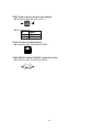
1. Checklist
G
501 mm
225 mm
191 mm
281 mm
93 mm
Pole Display Module
Flat Cable (DB-9P to DB-9P
Flat Cable Connector)
Base Unit
Two Pieces of Pole Support
(1x22cm, 1x9cm)
Installation Guide
Power Adapter
2. Features
1. Data can be display on 20 columns x 2 lines.
2. Blue–green color and large character are easy to see.
3. The DIP switches setting emulate commands mode, baud rate and international
character.
4. Command emulation modes include: POS7300, EPSON ESC/POS, ADM787/
ADM788, DSP800, AEDEX/ EMAX, UTC, and CD5220.
5. Display area can be controlled by window function.
6. Provides an interface based in RS-232C, and RS232C baud rate from 4800 to
38400 bps.
7. Reverse characters can be specified using the Epson command set.
7
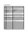
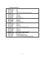
3. Specification
NO
Item
Description
1
Display method
Vacuum fluorescent display
2
Number of character
3
Character font
5 x 7 Dot matrix
4
Display color
Blue green
5
Brightness
700 cd /㎡
6
Character type
7
Character size
8
Power supply
9
Power consumption
3-6W
10
MTBF
25000 hours (power on time)
11
Panel dimensions
224 (W) x 93 (H) x 50(D) mm
12
Support dimensions
13
Base dimensions
190(w)x55(h)x96(d)mm
14
Viewing angle
-5 - 60 degrees
15
Rotation angle
Maximum 270 degrees
16
Weight
1.25 Kg
17
Operating temperature
5 - 45℃
18
Operating Humidity
30%-85%
19
Storage Temperature
-10 - 55℃
20
Storage Humidity
10%-85%
40 characters
(20 columns x 2 lines)
96 alphanumeric
13 kinds of international character set
9.0mm x 5.25mm
11-19VDC
Manufacture offer +12V power adapter
Long support :
22 cm
Short support :
9 cm
8
4. Interface
4.1.
Specification
Data transmission
Serial
Synchronization
Asynchronous
Handshaking
DTR / DSR
MARK = -3 to –15 V (logic “1”)
Signal level
SPACE = +3 to +15 V (logic “0”)
4.2.
Baud rates
4800,9600,19200,38400 bps
Parity
None, even
Bit length
8 bits
Stop bits
1 bit
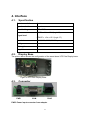
Display Base
The picture below shows the configuration of the stand alone VFD Pole Display base.
Figure of VFD Pole Display Base
4.3.
Connector
PWR
COM
RJ45
PWR: Power input connector from adapter
9
Connector type: DC jack (5.5/2.1)
Pin assignment
No
Signal
+
Vin
GND
RJ45: Connect to display panel
Connector type: Phone-jack 10P/8C
10
1
COM: RS232C link to PC/HOST connector (9-pin)
Connector type: D-sub 9 pin female
1
5
6
9
10
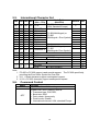
5. Dip Switch and Software Setting
5.1.
Command Type Selection
SW1
ON
OFF
ON
OFF
ON
OFF
ON
OFF
5.2.
SW2
ON
ON
OFF
OFF
ON
ON
OFF
OFF
SW9
ON
ON
OFF
OFF
Demo Mode Support
No
Yes
No
Yes
No
No
No
Yes
Baud Rate (bps)
4800
9600
19200
38400
Default
*
Parity Check Selection
SW10
ON
OFF
5.4.
Command Type
POS7300
EPSON ESC/POS
ADM 787/ ADM 788
DSP800
AEDEX/ EMAX
UTC/P
UTC/S
CD5220
Baud Rate Selection
SW8
ON
OFF
ON
OFF
5.3.
SW3
ON
ON
ON
ON
OFF
OFF
OFF
OFF
Parity Check
None-parity
Even-parity
Default
*
Demo Mode Selection
SW11
ON
OFF
Show Demo String
Enable
Disable
Default
*
11
Default
*
5.5.
International Character Set
SW4 SW5 SW6 SW7
Character Set
(20h – 7Fh)
ON
ON
ON
ON U.S.A.
OFF
ON
OFF
ON
OFF
ON
OFF
ON
OFF
ON
OFF
OFF
ON
ON
OFF
OFF
ON
ON
ON
ON
ON
OFF
OFF
OFF
OFF
ON
ON
ON
ON
ON
ON
ON
ON
ON
OFF
OFF
ON OFF ON OFF
OFF OFF ON OFF
ON ON OFF OFF
OFF ON OFF OFF
ON OFF OFF OFF
OFF OFF OFF OFF
FRANCE
GERMANY
U.K.
DENMARK I
SWEDEN
ITALY
SPAIN
JAPAN
NORWAY
Code Table
(80H-FFH)
PC-437
(USA, Standard Europe)
PC-850(Multilingual) or
PC-858
(Multilingual + Euro Symbol)
Katakana
PC-850(Multilingual) or
PC-858
DENMARK II
(Multilingual+ Euro Symbol)
Slawie
RUSSIA
U.S.A
PC860(Portuguese)
Not used
U.K.
Greek
Not used
U.S.A
PC-852(Hungary)
Default Note
*
1
1
1
1
1
1
1
1
1
2
2
3
3
Note:
1. PC-850 or PC-858 support need special request. The PC-858 specifically
providing the Euro Dollar Symbol on Char D5h.
2. U.K. + Greek character support need special request.
3. U.S.A + PC-852 character support need special request.
5.6.
Command Control
SW12
ON
OFF
Function
Depend on SW1~SW11 setting
By pass SW1~SW11 setting, fixed at:
1. Command type: POS7300,
2. Baud rate: 9600
3. Parity check: None-parity
4. Demo mode: Disable
5. International char set: USA, standard Europe
12
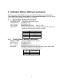
6. Software Status Setting Commands
When the system is POWER ON, it will read the DIP switch to set the Command
Type, Baud Rate, Parity, Demo Mode and International Character. User can re-set
the Software Status Setting Commands as following:
6.1.
Baud Rate Setting Command
STX 05 B n ETX
ASCII Format
Dec. Format
Hex. Format
Description
/Change the baud rate setting/
STX 05 B n ETX
[02][05][66] n [03]
[02h][05h][42h] n [03h]
30h≦n≦34h
Change the display communication baud rate. The baud rate
setting can be selected from 4800 to 38400.
n
30h
31h
32h
33h
6.2.
Baud rate
4800
9600
19200
38400
Parity Check Setting Command
STX 05 P n ETX
ASCII Format
Dec. Format
Hex. Format
Description
/Change the Parity check setting/
STX 05 P n ETX
[02][05][80] n [03]
[02h][05h][50h] n [03h] n=30h, 31h
Change the display communication parity. Set 8 data bit and
the parity set for even or non-parity.
n
30h
31h
Parity check
None-parity
Even-parity
13
6.3.
International Character Set Setting Command
STX 05 S n ETX
ASCII Format
Dec. Format
Hex. Format
Description
/Change the international character set/
STX 05 S N ETX
[02][05][83] n [03]
[02h][05h][53h] n [03h] 30h≦n≦3fh
Change the display international character font.
30h
31h
32h
33h
34h
35h
36h
37h
38h
39h
Character Set
(20h – 7Fh)
U.S.A.
FRANCE
GERMANY
U.K.
DENMARK I
SWEDEN
ITALY
SPAIN
JAPAN
NORWAY
3Ah
DENMARK II
3Bh
3Ch
3Dh
Slawie
RUSSIA
U.S.A
Not used
U.K.
Not used
U.S.A
N
3Eh
3Fh
Note:
1.
2.
3.
Code Table
(80H-FFH)
PC-437 (USA, standard Europe)
PC-850 (multilingual) or
PC-858 (multilingual+Euro Symbol)
Katakana
PC-850 (multilingual) or
PC-858
(multilingual+ Euro Symbol)
Default
Note
*
1
1
1
1
1
1
1
1
1
PC860 (Portuguese)
Greek
PC-852 (Hungary)
2
2
3
3
PC-850 or PC-858 support need special request. The PC-858 specifically
providing the Euro Dollar Symbol on Char D5h.
U.K. + Greek character support need special request.
U.S.A + PC-852 character support need special request.
14
6.4.
Command Type Setting Command
STX 05 C n ETX
ASCII Format
Dec. Format
Hex. Format
Description
n
30h
31h
32h
33h
6.5.
/Change the command type setting/
STX 05 C n ETX
[02][05][67] n [03]
[02h][05h][43h] n [03h]
30h≦ n ≦37h
This command will change the command type and initialize
the display.
The display emulation mode is based on DSP800/ ESC/ ADM
787/ POS7301/ AEDEX/ UTC/ CD5220 mode.
Command Type
POS7300
ESC/POS
ADM 787
DSP800
N
34h
35h
36h
37h
Command Type
AEDEX
UTC/P
UTC/S
CD5220
Show Firmware Version
STX 05 V 01 ETX
ASCII Format
Dec. Format
Hex. Format
Description
/Show Firmware Version/
STX 05 V 01 ETX
[02][05][86][01][03]
[02h][05h][56h][01h][03h]
Show firmware version.
15
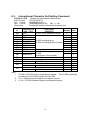
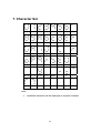
7. Command List Table
Command List Table – 1
EPSON
POS7300CD5220 D101 UTC/S UTC/P AEDEX ADM788 DSP800
Move cursor right
Move cursor left
Move cursor up
Move cursor down
Move cursor to right-most
position
Move cursor to left-most
position
Move cursor to home position
Move cursor to bottom position
Move cursor to specified
position
Clear display screen
Clear cursor line
Brightness adjustment
Blink display screen
Initialize display
Select character code table
Select international character
set
Select/cancel reverse
character
Overwrite mode
Vertical scroll mode
Horizontal scroll mode
Set/cancel the window range
Select peripheral device
Set starting/ending position of
macro definition
Execute and quit macro
Execute self-test
Display time
Display time continuously
Display position
Cursor on/off
Change to UTC enhanced
mode
Change to UTC standard
mode
Write string to upper line
O
O
O
O
O
O
O
O
O
O
O
O
O
O
O
O
O
O
O
O
O
O
O
O
O
O
O
O
O
O
O
O
O
O
O
O
O
O
O
O
O
O
O
O
O
O
O
O
O
O
O
O
O
O
O
O
O
O
O
O
O
O
O
O
O
O
O
O
O
O
O
O
O
O
O
O
O
O
O
O
O
O
O
O
O
O
O
16
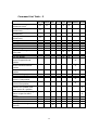
O
Command List Table – 2
EPSON
POS7300CD5220 D101 UTC/S UTC/P AEDEX ADM788 DSP800
Upper line message
continuous scroll
Bottom line message scroll
continuously
Message vertical down scroll
continuously
Message vertical upper scroll
continuously
Carriage return
Line feed
Back space
Horizontal tab
Command type select
Upper line message scroll
once pass
Change attention code
Two line display
Clear upper line and move
cursor to upper left-end
position
Clear bottom line and move
cursor to bottom left-end
position
Set period to upper line, last n
position
Set line blinking, upper line
Clear line blinking, upper line
Clear field 1 and move cursor
to field 1, first position
Clear field 2 and move cursor
to field 2,first position
Clear display range from n
position to m position and
move cursor to n position
Save the current displaying
data to n layer for demo
display
Turn annunciator on/off
Specify period
Specify comma
Specify semicolon (period +
comma)
O
O
O
O
O
O
O
O
O
O
O
O
O
O
O
O
O
O
O
O
O
O
O
O
O
O
O
O
O
O
O
O
O
O
O
O
O
O
O
O
17
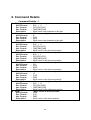
8. Command Details
8.1.
POS7300 Series Command List
Command
ESC F A .. CR
ESC F B .. CR
ESC F D .. CR
ESC F O .. CR
ESC P x y
ESC _ n
ESC DC1
ESC DC2
ESC DC3
ESC @
US MD2 n
US MD1 n
US DC1 n
US DC2 n
US E n
NULL H
NULL K
NULL M
NULL P
NULL G
NULL O
BS
HT
LF
HOM
CLR
CR
CAN
Code (hex)
1B 46 41 [DATA X 40] 0D
1B 46 42 [DATA X 40] 0D
1B 46 44 [DATA X 40] 0D
1B 46 4F [DATA X 40] 0D
1B 50 x y
1≦x≦14h,y=1,2
1B 5F n
n=00,01
1B 11
1B 12
1B 13
1B 40
1F 02 n
n=01~0Ch
1F 01 n
n=01~0Ch
1F 11 n
n=’1’,’2’
1F 12 n
n=’1’,’2’
1F 45 n
n=0~FFh
0 48
0 4B
0 4D
0 50
0 47
0 4F
08
09
0A
0B
0C
0D
18
18
Function Description
Write string to upper line
Write string to lower line
Upper line message scroll continuously
Bottom line message scroll continuously
Move cursor to specified position
Set cursor on/off
Overwrite mode
Vertical scroll mode
Horizontal scroll mode
Initialize display
Message vertical down scroll
continuously
Message vertical upper scroll
continuously
Set line blinking
N=’1’ up line, n=’2’ low line
Clear line blinking
N=’1’ up line, n=’2’ low line
Blink display screen
n=00h~FFh, n=0 for no blink
Move cursor up
Move cursor left
Move cursor right
Move cursor down
Move cursor to left-most position
Move cursor to right-most position
Back space
Horizontal tab
Line feed
Move cursor to home position
Clear display screen
Carriage return
Clear cursor line, and clear string mode
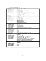
8.2.
CD5220 Standard Mode Command List
CD5220 Standard Mode Command List-1
Command
ESC DC1
US SOH
ESC DC2
US STX
ESC DC3
US ETX
ESC Q A .. CR
Code (hex)
1B 11
1F 01
1B 12
1F 02
1B 13
1F 03
1B 51 41 [n]x20 0D
ESC Q B .. CR
1B 51 42 [n]x20 0D
ESC Q D .. CR
1B 51 44 [n]xm 0D
m<40
ESD [ D
1B 5B 44
BS
08
ESC [ C
1B 5B 43
HT
09
ESC [ A
1B 5B 41
US LF
1F 0A
ESC [ B
1B 5B 42
LF
0A
ESC [ H
1B 5B 48
HOM
0B
ESC [ L
1B 5B 4C
CR
0D
ESC [ R
1B 5B 52
US CR
1F 0D
ESC [ K
1B 5B 4B
US B
1F 42
ESC # n
1B 23 n
n=30h~37h
US @
1F 40
US E n
1F 45 n
n=0~FFh
ESC I x y
1B 6C x y / 1F 24 x y
1≦x≦14h, y=1,2
US $ x y
1F 24 x y
1≦x≦14h,y=1,2
ESC @
1B 40
ESC W s x1 x2 y 1B 57 1 x1 x2 y
0≦x1≦x2≦13h y=1,2
S=0 cancel, 1 set
Function Description
Overwrite mode
Overwrite mode
Vertical scroll mode
Vertical scroll mode
Horizontal scroll mode
Horizontal scroll mode
Set the string display mode, write string to
upper line. *1
Set the string display mode, write string to
lower line. *1
Upper line message scroll continuously. *1
*2
Move cursor left
Move cursor left
Move cursor right
Move cursor right
Move cursor up
Move cursor up
Move cursor down
Move cursor down
Move cursor to home position
Move cursor to home position
Move cursor to left-most position
Move cursor to left-most position
Move cursor to right-most position
Move cursor to right-most position
Move cursor to bottom position
Move cursor to bottom position
Command type select
Execute self test
Blink display screen
n=00h~FFh, n=0 for no blink
Move cursor to specified position
Move cursor to specified position
Initialize display
Set or cancel the window range at
horizontal scroll mode
19
CD5220 Standard Mode Command List-2
Command
CLR
CAN
ESC * n
US X n
ESC _ n
ESC f n
ESC c n
ESC = n
Code (hex)
0C
18
1B 2A n
1≦n≦4
1F 58 n
1≦n≦4
1B 5F n
n=00,01
1B 66 n
1B 63 n
1B 3D n
n=01,02,03
Function Description
Clear display screen, and clear string mode
Clear cursor line, and clear string mode
Brightness adjustment
Brightness adjustment
Set cursor on/off
Select international fonts, refer. *3
Select fonts, ASCII code or JIS code, refer.
*4
Select peripheral device, display or printer
n=01,enable printer
n=02,enable display
n=03,enable printer, display
Note:
1. While using command “ESC Q A” or “ESC Q B”, other commands cannot be
used except when using command “CLR” or “CAN” to change operating
mode.
2. When using command “ESC Q D”, the upper line message will scroll
continuously until a new command is received, it will then clear the upper line
and move the cursor to the upper left-end position.
3. The parameter of international fonts set control by command “ESC f n”.
Parameter “n”
‘A’
41h
‘G’
47h
’I’
49h
‘J’
4Ah
‘U’
55h
‘F’
46h
‘S’
53h
‘N’
4Eh
‘W’
57h
‘D’
44h
‘E’
45h
‘L’
4Ch
‘R’
52h
International Font Set
U.S.A.
Germany
Italy
Japan
U.K.
France
Spain
Norway
Sweden
Denmark I
Denmark II
Slavonic
Russia
20
4. The parameter of the code table control by command “ESC c n”.
Parameter “n”
‘A’
41h
‘J’
4Ah
‘L’
4Ch
‘R’
52h
8.3.
UTC Standard Mode Command List
Command
BS
HT
LF
CR
DLE
DC1
DC2
DC3
DC4
US
ESC d
8.4.
International Font Set
Compliance with ASCII code
Compliance with JIS code
Compliance with SLOVONIC code
Compliance with RUSSIA code
Code (hex)
08
09
0A
0D
10 n
0≦n<28h
11
12
13
14
1F
1B 64
Function Description
Back space
Horizontal tab
Line feed
Carriage return
Display position
Over write display mode
Vertical scroll mode
Cursor on
Cursor off
Clear display
Change to UTC enhanced mode
UTC Enhanced Mode Command List
Command
ESC u A .. CR
ESC u B .. CR
ESC u D .. CR
ESC u E .. CR
ESC u F .. CR
ESC u H .. CR
ESC u I .. CR
ESC RS CR
Code (hex)
1B 75 41 [data x 40] 0D
1B 75 42 [data x 40] 0D
1B 75 44 [data x 40] 0D
1B 75 45 h h ':' m m 0D
h, m = '0' - '9'
1B 75 46 [data x 40] 0D
1B 75 48 n m 0D
20h≦n,m
1B 75 49 [data x 40] 0D
1B 0F 0D
Function Description
Upper line display
Bottom line display
Upper line message scroll continuously
Display time
Upper line message scroll Once pass
Change attention code
Two line display
Change to UTC standard mode
21
8.5.
AEDEX/EMAX Mode Command List
Command
! # 4 … CR
! # 5 … CR
! # 8 … CR
! # 9 … CR
! # 6 … CR
8.6.
DC0
DC1
DC2
SF1
SF2
Function Description
Upper line message scroll
Display time
Change attention code
Two line display
Upper line message scroll once pass
ADM787/788 mode command list
Command
CLR
CR
SLE1
SLE2
Code (hex)
21 23 34 [data x 40] 0D
21 23 35 h h ':' m m 0D
h,m='0'-'9'
21 23 38 n m 0D
20h≦n,m
21 23 39 [data x 40] 0D
21 23 36 [data x 40] 0D
Code (hex)
Function Description
0C
Clear display
0D
Carriage return
0E
Clear upper line and move cursor to upper left-end
position
0F
Clear bottom line and move, Cursor to bottom left-end
position
10 n
Set period to upper line last n position, 31H≦n≦37H
11 n
Set line blinking, upper line
n='1' up line, n='2' low line
12 n
Clear line blinking, upper line
n='1' up line, n='2' low line
1E
Clear field 1 and move cursor to field 1, first position
1F
Clear field 2 and move cursor to field 2, first position
22
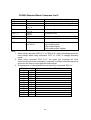
8.7.
DSP800 Mode Command List
Command
EOT SOH I n ETB
Code (hex)
04 01 49 n 17
n=00~0Fh or 30~3Fh
EOT SOH P n ETB 04 01 50 n 17
n=31h-58h
EOT SOH C n m
04 01 43 n m 17
ETB
31h≦n≦m≦58h
EOT SOH S n ETB 04 01 53 n 17
n=31h-35h
EOT SOH D n m
04 01 44 n m 17
ETB
n=31h-4Fh,m=31h-33h
EOT SOH A n ETB 04 01 41 n 17
n=31h-34h
EOT SOH F n ETB 04 01 46 n 17
00h≦n≦FFh
EOT SOH = n ETB 04 01 3D n 17
n='1', '2', '3'
EOT SOH % ETB
EOT SOH @ ETB
EOT SOH # n ETB
04 01 25 17
04 01 40 17
04 01 23 n 17
n=30~37h
23
Function Description
Select international character set
Move cursor to specified position
Clear display range from n position
to m position and move cursor to n
position
Save current view message to n
layer for demo view data
Display the saved demo message
Brightness adjustment
Blink display Screen
n=00h~FFh, n=0 for no blink
Select peripheral device.
n='1',enable printer
n='2',enable display
n='3',enable printer display
Initialize display
Execute self-test
Command type select
8.8.
EPSON ESC/POS Command List
EPSON ESC/POS Command List-1
Command
Code (hex)
ESC t n
1B 74 n
n=00-0Fh
ESC R n
1B 52 n
n=00-0Fh
US r n
1F 72 n
n=00,01
US MD1
1F 01
US MD2
1F 02
US MD3
1F 03
CAN
18
ESC # n
1B 23 n
30h≦n≦38h
US # n m
1F 23 n m,
n=0 or 1,0<m≦14h
US C n
1F 43 n
n=00, 01
BS
08
HT
09
US LF
1F 0A
LF
0A
US CR
1F 0D
CR
0D
HOM
0B
US B
1F 42
US $ x y
1F 24 x y
1≦x≦14h,y=1 or 2
CLR
0C
US E n
1F 45 n
n=00h~FFh
ESC @
1B 40
US . n
1F 2E n
n=a displayable character code
US , n
1F 2C n
n=a displayable character code
US ; n
1F 3B n
n=a displayable character code
24
Function Description
Select character code table.
See note *2
Select international character set.
See note *1
Select/cancel reverse character.
Specify overwrite mode.
Specify vertical scroll mode.
Specify horizontal scroll mode.
Clear cursor line
Command type select
Turn annunciator on/off
Set cursor on/off
Move cursor left
Move cursor right
Move cursor up
Move cursor down
Move cursor to right-most position
Move cursor to left-most position
Move cursor to home position
Move cursor to bottom position
Move cursor to specified position
Clear display screen
Blink display screen
n=00h~FFh, n=0 for no blink
Initialize display
Specify period
Specify comma
Specify semicolon (period + comma)
EPSON ESC/POS Command List-2
Command
Code (hex)
ESC W n s x1 1B 57 n s x1 y1 x2 y2
y1 x2 y2
n=1,2,3,4
s=0,1
ESC = n
1B 3D n
n=01, select printer
n=02, select display
n=03, select printer, display
US :
1F 3A
US ^ n m
US @
US T h m
US U
1F 5E n m
00≦ (n, m)≦ff
n=Word time
m=show string time
1F 40
1F 54 h m
0<=h<=17h,
0<=m<=3bh
1F 55
Function Description
Specify/cancel the window range.
1<=x1<=x2<=20
1<=y1<=y2<=2
Select peripheral device.
Set starting/ending position of macro
definition.
Ex.: 1F 3A … (macro string) … 1F 3A
Execute and quit macro. It’s an
interval of n between the two words.
It’s an interval of m between the two
strings.
Execute self - test
Display time
Display time continuously
Note:
1. Select international character set for ESC/POS
n
International Font Set
n International Font Set
0h U.S.A.
8h JAPAN
1h FRANCE
9h NORWAY
2h GERMANY
Ah DENMARK II
3h U.K.
Bh SLAVONIC
4h DENMARK I
Ch RUSSIA
5h SWEDEN
Dh U.S.A.
6h ITALY
Eh No used/ U.K
7h SPAIN
Fh No used/ U.S.A
2. Select character code table for ESC/POS
n
International Font Set (80H~FFH)
0h Page 0, (PC437: U.S.A., standard Europe)
1h Page 1, (Katakana for Japan)
2h Page 2, (PC858: multilingual+ Euro Symbol)
3h Page 3, (PC860: Portuguese)
4h Page 4, (PC863: Canadian-French)
5h Page 5, (PC865: Nordic)
6h Page 6, (Slavonic)
7h Page 7, (Russia)
8h Page 8, (Greek)
9h Page 9, (PC852: Hungary)
25
9. Character Set
9.1.
Character Code 20H – 7EH
9.1.1
International Character Sets
Character Code Number
Hex 23
24
40
5B
5C
5D
5E
60
7B
Dec 35
36
64
91
92
93
94
96
123 124 125 126
U.S.A
#
$
@
[
\
]
^
`
{
|
}
~
France
#
$
à
°
ç
§
^
`
é
ù
è
¨
Germany
#
$
§
Ä
Ö
Ü
^
`
ä
ö
ü
β
U.K
£
$
@
[
\
]
^
`
{
|
}
~
Denmark I
#
$
@
Æ
Ø
Å
^
`
æ
ø
å
~
Sweden
#
¤
É
Ä
Ö
Å
Ü
é
ä
ö
å
ü
Italy
#
$
@
°
\
é
^
ù
à
ò
è
ì
Spain
Pt
$
@
¡
Ñ
¿
^
`
¨
ñ
}
~
Japan
#
$
@
[
¥
]
^
`
{
|
}
~
Norway
#
¤
É
Æ
Ø
Å
Ü
é
æ
ø
å
ü
Denmark II
#
$
É
Æ
Ø
Å
Ü
é
æ
ø
å
ü
Slavonic
#
$
@
[
\
]
^
`
{
|
}
~
Russia
#
$
@
[
\
]
^
`
{
|
}
~
Country
9.1.2
7C
7D
7E
USA, Standard Character Sets
00
01
02
03
04
05
06
07
08
09
0A
0B
0C
0D
0E
0F
20H
SP
!
“
#
$
%
&
‘
(
)
*
+
,
-
.
/
30H
0
1
2
3
4
5
6
7
8
9
:
;
<
=
>
?
40H
@
A
B
C
D
E
F
G
H
I
J
K
L
M
N
O
50H
P
Q
R
S
T
U
V
W
X
Y
Z
[
\
]
^
_
60H
`
a
b
c
d
e
f
g
h
i
j
k
l
m
n
o
70H
p
q
r
s
t
u
v
w
x
y
Z
{
|
}
~
SP
26
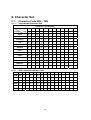
9.2.
Character Code 80H – FFH
9.2.1
Page 0 (PC437: USA, Standard Europe)
00
01
02
03
04
05
06
07
08
09
0A
0B
0C
0D
0E
0F
80H
Ç
ü
é
â
ä
à
å
ç
ê
ë
è
ï
î
ì
Ä
Å
90H
É
æ
Æ
ô
ö
ò
û
ù
ÿ
ö
Ü
¢
£
¥
Pt
ƒ
A0H
á
í
ó
ú
ñ
Ñ
ª
º
¿
⌐
¬
½
¼
¡
«
»
B0H
░
▒
▓
│
┤
╡
╢
╖
╕
╣
║
╗
╝
╜
╛
┐
C0H
└
┴
┬
├
─
┼
╞
╟
╚
╔
╩
╦
╠
═
╬
╧
D0H
╨
╤
╥
╙
╘
╒
╓
╫
╪
┘
└
█
▄
▌
▐
▀
E0H
α
ß
Γ
π
Σ
σ
µ
τ
Ф
θ
Ω
δ
∞
ø
є
∩
n
²
■
SP
F0H
9.2.2
80H
≡
±
≥
≤
⌠
⌡
÷
≈
°
•
·
√
Page 1 (Katakana for Japan)
00
01
02
03
04
05
06
07
08
09
0A
0B
0C
0D 0E
0F
α
β
γ
⊿
є
η
θ
λ
µ
π
ρ
σ
τ
Ф
Ω
∑
Ā
-1
³
x
½
1
√
±
■
"
∘
∴
∵
♁
Θ
90H
£
§
IE
IR
∫
x
A0H
SP
。
「
」
、
‧
²
/
B0H
C0H
D0H
E0H
↑
↓
←
→
←
→
→
←
←
→
”
“
«
F0H
≤
≥
≠
≒
║
│
⊥
∞
α
~
~
≣
〒
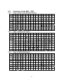
9.2.3
»
Page 2 (PC850: Multilingual)
00
01
02
03
04
05
06
07
08
09
0A
0B
0C
0D
0E
0F
80H
Ç
ü
é
â
ä
à
å
ç
ê
ë
è
ï
î
ì
Ä
Å
90H
É
æ
Æ
ô
ö
ò
û
ù
ÿ
ö
Ü
ø
£
Ø
×
ƒ
A0H
á
í
ó
ú
ñ
Ñ
a
o
¿
®
¬
½
¼
¡
«
»
B0H
░
▒
▓
│
┤
Á
Â
À
©
╣
║
╗
╝
¢
¥
┐
C0H
└
┴
┬
├
─
┼
ã
Ã
╚
╔
╩
╦
╠
═
╬
¤
D0H
ð
Đ
Ê
Ë
È
€
Í
Î
Ï
┘
「
█
▄
¦
Ì
▀
E0H
ó
ß
ô
ò
õ
Õ
µ
þ
Þ
Ú
Û
Ù
ý
Ý
¯
´
F0H
¯
±
‗
¾
¶
§
÷
,
˚
¨
˙
1
3
2
■
SP
27
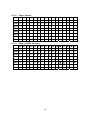
9.2.4
Page 2 (PC858: Multilingual + Euro Symbol)
01
02
03
04
05
06
07
08
09
0A
0B
0C
0D
0E
0F
80H
Ç
ü
é
â
ä
à
å
ç
ê
ë
è
ï
î
ì
Ä
Å
90H
É
æ
Æ
ô
ö
ò
û
ù
ÿ
ö
Ü
ø
£
Ø
×
ƒ
A0H
á
í
ó
ú
ñ
Ñ
a
o
¿
®
¬
½
¼
¡
«
»
B0H
░
▒
▓
│
┤
Á
Â
À
©
╣
║
╗
╝
¢
¥
┐
C0H
└
┴
┬
├
─
┼
ã
Ã
╚
╔
╩
╦
╠
═
╬
¤
D0H
ð
Đ
Ê
Ë
È
€
Í
Î
Ï
┘
「
█
▄
¦
Ì
▀
E0H
ó
ß
ô
ò
õ
Õ
µ
þ
Þ
Ú
Û
Ù
ý
Ý
¯
´
F0H
¯
±
=
¾
¶
§
÷
¨
˙
1
3
2
■
SP
,
00
˚
00
01
02
03
04
05
06
07
08
09
0A
0B
0C
0D
0E
0F
80H
Ç
ü
é
â
ã
à
Á
ç
ê
Ê
è
Í
Ô
ì
Ã
Â
90H
É
À
È
ô
õ
ò
Ú
ù
Ì
Õ
Ü
¢
£
Ù
Pt
Ó
A0H
á
í
ó
ú
ñ
Ñ
a
o
¿
®
¬
½
¼
¡
«
»
B0H
░
▒
▓
│
┤
╡
╢
╖
╕
╣
║
╗
╝
╜
╛
┐
C0H
└
┴
┬
├
─
┼
╞
╟
╚
╔
╩
╦
╠
═
╬
╧
D0H
╨
╤
╥
╙
╘
╒
╓
╫
╪
┘
└
█
▄
▌
▐
▀
E0H
α
β
Γ
π
Σ
σ
µ
τ
Ф
θ
Ω
δ
∞
ø
є
∩
F0H
≡
±
≥
≤
⌠
⌡
÷
≈
°
•
·
√
n
²
■
SP
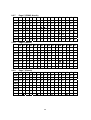
9.2.5
9.2.6
Page 3 (PC860: Portuguese)
Page 4 (PC863: Canadian- French)
00
01
02
03
04
05
06
07
08
09
0A
0B
0C
0D
0E
0F
80H
Ç
ü
é
â
ä
à
å
ç
ê
ë
è
ï
î
ì
Ä
Å
90H
É
æ
Æ
ô
ö
ò
û
ù
ÿ
ö
Ü
ø
£
Ø
×
ƒ
A0H
á
í
ó
ú
ñ
Ñ
a
o
¿
®
¬
½
¼
¡
«
»
B0H
░
▒
▓
│
┤
Á
Â
À
©
╣
║
╗
╝
¢
¥
┐
C0H
└
┴
┬
├
─
┼
ã
Ã
╚
╔
╩
╦
╠
═
╬
¤
D0H
ð
Đ
Ê
Ë
È
€
Í
Î
Ï
┘
「
█
▄
¦
Ì
▀
E0H
ó
ß
ô
ò
õ
Õ
µ
þ
Þ
Ú
Û
Ù
ý
Ý
¯
´
F0H
¯
±
‗
¾
¶
§
÷
,
˚
¨
˙
1
3
2
■
SP
28
9.2.7
Page 5 (PC865: Nordic)
00
01
02
03
04
05
06
07
08
09
0A
0B
0C
0D
0E
0F
80H
Ç
ü
é
â
ä
à
å
ç
ê
ë
è
ï
î
ì
Ä
Å
90H
É
æ
Æ
ô
ö
ò
û
ù
ÿ
Ö
Ü
ø
£
Ø
Pt
ƒ
A0H
á
í
ó
ú
ñ
Ñ
a
o
¿
®
¬
½
¼
¡
«
»
B0H
░
▒
▓
│
┤
Á
Á
Á
0
╣
║
╗
╝
¢
¥
┐
C0H
└
┴
┬
├
─
┼
ã
Ã
╚
╔
╩
╦
╠
═
╬
¤
D0H
ð
Đ
Ê
Ë
È
€
Í
Î
Ï
┘
「
█
▄
¦
Ì
▀
E0H
ó
ß
ô
ò
õ
Õ
µ
þ
Þ
Ú
Û
Ù
ý
Ý
¯
´
F0H
¯
±
‗
¾
¶
§
÷
,
˚
¨
˙
1
3
2
■
SP
0A 0B 0C 0D
0E
0F
9.2.8
Page 6 (Slawie)
00
01
02
03
04
05
06
07
08
09
80H
Ç
ü
é
â
ä
ů
ć
ç
Į
ë
õ
õ
î
ź
ä
ć
90H
é
Ĺ
í
ô
ö
Ľ
ĭ
ś
ś
Ö
Ü
ť
ť
ł
х
č
A0H
á
í
ó
ú
ą
ą
ž
ž
ę
ę
ź
č
ş
«
»
B0H
░
▒
▓
│
┤
á
â
ĕ
ş
ŧ
ŧ
─
┼
ă
ă
C0H
═
D0H
đ
đ
ď
ë
ď
ň
í
î
ě
E0H
ó
β
ô
ń
ń
ň
š
š
ŕ
ú
F0H
–
̃
ֽ
ˇ
˘
§
÷
د
˚
9.2.9
¤
█
▄
ţ
ů
▀
ŕ
ũ
ý
ý
ţ
́
¨
˙
ũ
ř
ř
■
SP
Page 7 (Russia)
00
01
02
03
04
05
06
07
08
09
0A
0B
0C
0D
0E
0F
80H
А
Б
В
Г
Д
Е
Ж
З
и
Й
К
Л
М
Н
О
П
90H
Р
С
Т
У
Ф
Х
Ц
Ч
Ш
Щ
Ъ
Ы
Ь
Э
Ю
Я
A0H
а
б
в
г
д
е
ж
з
и
й
к
л
м
н
о
п
E0H
р
с
т
у
ф
х
ц
ч
ш
щ
ъ
ы
ь
э
ю
́я
F0H
∂
Ґ
K
H
θ
Y
Y
h
∂
ґ
k
H
θ
Y
Y
SP
B0H
C0H
D0H
29
9.2.10
Page 8 (Greek)
00
01
02
03
04
05
06
07
08
09
0A 0B 0C 0D
0E
0F
80H
Α
Β
Γ
∆
Ε
Ζ
Η
Θ
Ι
Κ
Λ
Μ
Ν
Ξ
Ο
Π
90H
Ρ
Σ
Τ
Y
Φ
Х
Ψ
Ω
α
β
γ
δ
ε
ζ
η
θ
A0H
ι
κ
λ
µ
ν
ξ
ο
π
ρ
σ
s
τ
υ
φ
χ
ψ
B0H
C0H
D0H
E0H
ω
£
F0H
9.2.11
-
Page 9 (PC852: Hungary)
00
01
02
03
04
05
06
07
08
09
0A 0B 0C 0D
0E
0F
80H
Ç
ű
é
â
ä
ů
ć
ç
ł
ë
Ő
ő
î
Ź
Ä
Ć
90H
É
Ĺ
ĺ
ô
ö
Ľ
ľ
Ś
ś
Ö
Ü
Ť
ť
Ł
x
Č
A0H
á
í
ó
ú
Ą
ą
Ž
ž
Ę
ę
¬
ź
Č
ş
«
»
B0H
░
▒
▓
│
┤
Á
Â
Ĕ
Ş
╣
║
╗
╝
ż
ż
┐
C0H
└
┴
┬
├
─
┼
Ä
ǎ
╚
╔
╩
╦
╠
═
╬
¤
D0H
đ
Đ
Ď
Ë
ď
Ň
Í
Î
ě
┘
г
█
▄
Ţ
Ů
▀
E0H
Ó
ß
Ô
Ń
ń
ň
Š
š
Ŕ
Ú
ŕ
Ű
ý
Ý
ţ
´
F0H
–
̃
ֽ
ˇ
˘
§
÷
د
˚
¨
˙
ũ
ř
ř
■
SP
30
10.
Display Module Dimension
200mm
0.38o
176mm
39mm 70mm
158.6mm
5.25mm
0.85mm
0.25mm
1.05mm
0.25mm
9.0mm
9.5mm
1.5mm
22.5mm
1.5mm
1.5mm
6.65mm
31
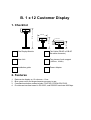
B. 1 x 12 Customer Display
1. Checklist
G
501 mm
225 mm
191 mm
281 mm
93 mm
Pole Display Module
Flat Cable (DB-9P to DB-9P
flat cable connector)
Base Unit
Two pieces of pole support
(1x22cm, 1x9cm)
Installation guide
Power Adapter
2. Features
1.
2.
3.
4.
Data can be display on 12 columns x 1 line.
Blue–green color and large character are easy to see.
Command emulation modes include: POS7300, EPSON ESC/POS.
Provides an interface based in RS-232C, and RS232C baud rate 9600 bps.
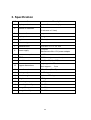
3. Specification
NO
Item
Description
1
Display method
Vacuum fluorescent display
2
Number of character
3
Character font
7 segment
4
Display color
Blue green
5
Brightness
700 cd /㎡
6
Character type
10 numeric
7
Character size
dot matrix 17.0 x 5.4 mm
8
Power supply
9
Power consumption
3-6W
10
MTBF
25000 hours (power on time)
11
Panel dimensions
224 (W) x 93 (H) x 50(D) mm
12
Support dimensions
13
Base dimensions
19.7 x 10 cm (W x D)
14
Viewing angle
-5 - 60 degrees
15
Rotation angle
Maximum 270 degrees
16
Weight
1.25 Kg
17
Operating temperature
5 - 45℃
18
Operating Humidity
30%-85%
19
Storage Temperature
-10 - 55℃
20
Storage Humidity
10%-85%
40 characters
(12 columns x 1 lines)
11-19VDC
Manufacture offer +12V power adapter
Long support :
22 cm
Short support :
9 cm
33
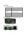
4. Interface
4.1.
Interface Specification
Data transmission
Serial
Synchronization
Asynchronous
Handshaking
DTR / DSR
MARK = -3 to –15 V (logic “1”)
Signal level
SPACE = +3 to +15 V (logic “0”)
4.2.
Baud rates
9600 bps
Parity
None
Bit length
8 bits
Stop bits
1 bit
Display Base
Below illustrate the configuration of Stand alone VFD Pole Display base.
Figure of VFD Pole Display Base
4.3.
Connector
PWR
COM
RJ45
34
PWR: Power input connector from adapter
Connector type: DC jack (5.5/2.1)
Pin assignment
No
Signal
+
Vin
GND
RJ45: Connect to display panel
Connector type: Phone-jack 10P/8C
10
1
COM: RS232C link to PC/HOST connector (9-pin)
Connector type: D-sub 9 pin female
1
5
6
9
35
5. Command List Table
Command List Table – 1
Command
ESC @
ESC D
ESC O m
ESC B m
ESC [ D
SO
ESC [ C
SI
ESC [ H
ESC [ L
CR
LF
ESC [ R
HOM
ESC [ K
ESC l x y
ESC P x y
CLR
CAN
.
Code (Hex)
1B 40
1B 44
1B 4F m (m= 1 or 2)
1B 42 m (1 <= m <= 3)
1B 5B 44
0E
1B 5B 43
0F
1B 5B 48
1B 5B 4C
0D
0A
1B 5B 52
0B
1B 5B 4B
1B 6C x y
(1 <= x <= 12, y=1)
1B 50 x y
(1 <= x <= 12, y=1)
0C
12
2E
Function Description
Initialize display
Enable the demo mode
Display ON or OFF
Adjust the brightness level
Move cursor left
Move cursor left
Move cursor right
Move cursor right
Move cursor to home position
Move cursor to left-most position
Move cursor to left-most position
Move cursor to left-most position
Move cursor to right-most position
Move cursor to home position
Move cursor to bottom position
Move cursor to specified position
Move cursor to specified position
Clear display screen
Clear cursor line
Set the pointer mark on the last show
character location
ESC . x m
1B 2E x m
Set the pointer mark ON or OFF on
(1 <= x <= 12, m= 0 or 1) specified position
‘
27
Set the comma mark on the last show
character location
ESC ‘ x m
1B 27 x m
Set the comma mark ON or OFF on
(1 <= x <= 12, m= 0 or 1) specified position
ESC Q A … CR 1B 51 41 D1D2...Dn 0D
Set the string display
(0 <= n <= 12)
(2Dh <= Dn <= 79h)
ESC F A … CR 1B 51 41 D1D2...Dn 0D
Set the string display
(0 <= n <= 12)
(2Dh <= Dn <= 79h)
ESC - m
1B 2D m
Set left-most dash ON or OFF
(m= 1 or 2)
ESC _ n
1B 5F n
Set cursor ON or OFF
(n= 0 or 1)
36
Command List Table – 2
Command
US E n
BS
NULL K
NULL M
NULL G
NULL O
Code (Hex)
1F 45 n
(n= 0 ~ FF)
08
00 4B
00 4D
00 47
00 4F
Function Description
Blink display screen
n=00h~FFh, n=0 for disable blink
Back space
Move cursor left
Move cursor right
Move cursor to left-most position
Move cursor to right-most position
37
6. Command Details
Command Details – 1
ESC [ C
ASCII Format
Dec. Format
Hex. Format
Description
SI
ASCII Format
Dec. Format
Hex. Format
Description
ESC [ H
ASCII Format
Dec. Format
Hex. Format
Description
ESC [ L
ASCII Format
Dec. Format
Hex. Format
Description
CR
ASCII Format
Dec. Format
Hex. Format
Description
LF
ASCII Format
Dec. Format
Hex. Format
Description
ESC [ R
ASCII Format
Dec. Format
Hex. Format
Description
HOM
ASCII Format
Dec. Format
Hex. Format
Description
:
:
:
:
:
:
:
:
:
:
:
:
:
:
:
:
:
:
:
:
:
:
:
:
:
:
:
:
:
:
:
:
/ Move cursor right /
ESC [ C
[027] [091] [067]
[1Bh] [5Bh] [43h]
Move cursor one character to the right
/ Move cursor right /
SI
[015]
[0Fh]
Move cursor one character to the right
/ Move cursor to home position /
ESC [ H
[027] [091] [072]
[1Bh] [5Bh] [48h]
Move cursor to the left-most position
/ Move cursor to left-most position /
ESC [ L
[027] [091] [076]
[1Bh] [5Bh] [4Ch]
Move cursor to the left-most position
/ Move cursor to left-most position /
CR
[013]
[0Dh]
Move cursor to the left-most position
/ Move cursor to left-most position /
LF
[010]
[0Ah]
Move cursor to the left-most position
/ Move cursor to right-most position /
ESC [ R
[027] [091] [082]
[1Bh] [5Bh] [52h]
Move cursor to the right-most position
/ Move cursor to home position /
HOM
[011]
[0Bh]
Move cursor to the home position
38
Command Details – 2
ESC [ K
ASCII Format
Dec. Format
Hex. Format
Description
ESC l x y
ASCII Format
Dec. Format
Hex. Format
Description
ESC P x y
ASCII Format
Dec. Format
Hex. Format
Description
CLR
ASCII Format
Dec. Format
Hex. Format
Description
CAN
ASCII Format
Dec. Format
Hex. Format
Description
:
:
:
:
:
:
:
:
:
:
:
:
:
:
:
:
:
:
:
:
.
ASCII Format
Dec. Format
Hex. Format
Description
ESC @
ASCII Format
Dec. Format
Hex. Format
Description
ESC D
ASCII Format
Dec. Format
Hex. Format
Description
:
:
:
:
:
:
:
:
:
:
:
:
/ Move cursor to bottom position /
ESC [ R
[027] [091] [075]
[1Bh] [5Bh] [4Bh]
Move cursor to the right-most position
/ Move cursor to specified position /
ESC l x y
[027] [108] [x] [y]
(1 <= x <= 12)
[1Bh] [6Ch] [x] [y] (y=1)
Move cursor to the x’th column on the y’th line.
/ Move cursor to specified position /
ESC P x y
[027] [80] [x] [y]
(1 <= x <= 12)
[1Bh] [50h] [x] [y]
(y=1)
Move cursor to the x’th column on the y’th line.
/ Clear display screen /
CLR
[012]
[0Ch]
Clear all of the displayed characters
/ Clear cursor line /
CAN
[018]
[12h]
Clear the line containing the display
/ Set the pointer mark on last show character location
/
.
[046]
[2Eh]
Set the pointer mark on last show character location.
/ Initialize display /
ESC @
[027] [064]
[1Bh] [40h]
Clear the data in the input buffer and setting.
/ Enable the demo mode /
ESC D
[027] [068]
[1Bh] [44h]
Enable the demo mode. Send any word can exit the
demo mode.
39
Command Details – 3
ESC O m
ASCII Format
Dec. Format
Hex. Format
Description
:
:
:
:
ESC B m
ASCII Format
Dec. Format
Hex. Format
Description
:
:
:
:
ESC [ D
ASCII Format
Dec. Format
Hex. Format
Description
SO
ASCII Format
Dec. Format
Hex. Format
Description
:
:
:
:
:
:
:
:
ESC . x m
ASCII Format
Dec. Format
Hex. Format
Description
:
:
:
:
ASCII Format
Dec. Format
Hex. Format
Description
:
:
:
:
‘
/ Display ON or OFF /
ESC O m
[027] [079] [m]
(m= 1 or 2)
[1Bh] [4Fh] [m]
Clear the data in the input buffer and setting.
m=1: Display ON (Default)
m=2: Display OFF
/ Adjust the brightness level /
ESC B m
[027] [066] [m]
(1 <= m <= 3)
[1Bh] [42h] [m]
Adjust the brightness level
m=1: low level
m=2: middle level
m=3: high level (Default)
/ Move cursor left /
ESC [ D
[027] [091] [068]
[1Bh] [5Bh] [44h]
Move cursor one character to the left
/ Move cursor left /
SO
[014]
[0Eh]
Move cursor one character to the left
/ Set the pointer mark ON or OFF on specified
position /
ESC . x m
[027] [046] [x] [m] (1 <= x <= 12)
[1Bh] [2Eh] [x] [m] (m= 0 or 1)
Set the pointer mark ON or OFF at x position.
m=0: Clear the pointer mark at x position
m=1: Set the pointer mark at x position
/ Set the comma mark on last show character
location /
‘
[039]
[27h]
Set the comma mark on last show character location.
40
Command Details – 4
/ Set the comma mark ON or OFF on specified
position /
ASCII Format
: ESC ‘ x m
Dec. Format
: [027] [039] [x] [m] (1 <= x <= 12)
Hex. Format
: [1Bh] [27h] [x] [m] (m= 0 or 1)
Description
: Set the pointer mark ON or OFF at x position.
m=0: Clear the comma mark at x position
m=1: Set the comma mark at x position
ESC Q A [D1 D2 .. Dn] CR / Set the string display /
ASCII Format
: ESC Q A D1D2…Dn CR
Dec. Format
: [027] [081] [065]
(0 <= n <= 12)
D1D2…Dn [013]
Hex. Format
: [1Bh] [51h] [41h]
(2Dh <= Dn <= 79h)
D1D2…Dn [0Dh]
Description
: Set the string display mode.
The string display mode will be cancel with CLR or CAN.
ESC F A [D1 D2 .. Dn] CR / Set the string display /
ASCII Format
: ESC F A D1D2…Dn CR
Dec. Format
: [027] [070] [065]
(0 <= n <= 12)
D1D2…Dn [013]
Hex. Format
: [1Bh] [46h] [41h]
(2Dh <= Dn <= 79h)
D1D2…Dn [0Dh]
Description
: Set the string display mode.
The string display mode will be cancel with CLR or CAN.
ESC - m
/ Set left-most dash ON or OFF /
ASCII Format
: ESC – m
Dec. Format
: [027] [045] [m]
(m= 1 or 2)
Hex. Format
: [1Bh] [2Dh] [m]
Description
: Set left-most dash on/off.
m=1: Display
m=2: No display (Default)
ESC _ n
/ Set cursor ON or OFF /
ASCII Format
: ESC _ n
Dec. Format
: [027] [095] [n]
(n= 0 or 1)
Hex. Format
: [1Bh] [5Fh] [n]
Description
: Set cursor on/off.
n=0: Display
n=1: No display (Default)
US E n
/ Blink display screen /
ASCII Format
: US _ n
Dec. Format
: [031] [069] [n]
(n= 0 ~ 255)
Hex. Format
: [1Fh] [45h] [n]
(n= 0 ~ FFh)
Description
: Blink display screen
n=00h~FFh, n=0 for no blink
ESC ‘ x m
41
Command Details – 5
BS
/ Back space /
ASCII Format
: BS
Dec. Format
: [08]
Hex. Format
: [08h]
Description
: Move cursor left and clean the character.
NULL K
/ Move cursor left /
ASCII Format
: NULL K
Dec. Format
: [00] [075]
Hex. Format
: [00h] [4Bh]
Description
: Move cursor left
NULL M
/ Move cursor right /
ASCII Format
: NULL M
Dec. Format
: [00] [077]
Hex. Format
: [00h] [4Dh]
Description
: Move cursor right
NULL G
/ Move cursor to left-most position /
ASCII Format
: NULL G
Dec. Format
: [00] [071]
Hex. Format
: [00h] [47h]
Description
: Move cursor to left-most position
NULL O
/ Move cursor to right-most position /
ASCII Format
: NULL O
Dec. Format
: [00] [079]
Hex. Format
: [00h] [4Fh]
Description
: Move cursor to right-most position
STX 05 V 01 TEX / Show firmware version /
ASCII Format
: NULL O
Dec. Format
: [02] [05] [86] [01] [03]
Hex. Format
: [02h] [05h] [56h] [01h] [03h]
Description
: Show the firmware version on the screen
42
7. Character Set
0
1
2
3
4
5
6
7
8
9
A/a
B/b
C/c
D/d
E/e
F/f
G/g
H/h
I/i
J/j
K/k
L/l
M/m
N/n
O/o
P/p
Q/q
R/r
S/s
T/t
U/u
V/v
W/w
X/x
Y/y
Z/z
Space
-
=
/
[
]
_
Note:
¾
Undefined characters will be displayed as a space character.
43
8. Display Module Dimension
44
(2 x 20 Customer Display and 1 x 12 Customer Display)
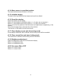
Appendix A - Command Details
A.1. Overwrite mode
In this mode, the cursor will move rightward and begin from the upper left-end position.
When the cursor has reached the end of the upper line, the cursor will move down to
the bottom left-end position to continue. When the cursor has reached the end of the
bottom line, it will move to up the upper left-end position and overwrite the previous
characters.
A.2. Vertical scroll mode
In this mode, the cursor will move rightward. The cursor will begin from the upper
left-end position until it has reached the end of the upper line. The cursor will then
move down to the bottom left-end position to continue until it has reached the end of
the bottom line.
A.3. Horizontal scroll mode
In this mode, the extent of the cursor activity is bound by a predefined range, limited to
the upper line. (Please refer to Set or cancel window command), where the default
window is the whole upper line. The cursor will begin from the left-end of the range
and move rightward until it reached the end of the range, to continue, the characters
that comes thereafter will start pushing the previous characters leftward from the
right-end, scrolling the characters to the left.
A.4. Set the string display mode and write string to display
Set the string display mode, write to upper or lower line d1 d2 d3 … dn {1≦n≦20}.
‘A’ stands for the upper line, ‘B’ stands for the lower line. The string display mode will
be cancelled and the display will return to the previous mode after receiving CLR or
CAN.
A.5. Upper line message continuous scroll
The message (previously defined) will scroll continuously in the horizontal direction
until a new command is received.
A.6. Move cursor left
When the current cursor is at the left-end position, this command operates differently
depending on the display mode.
Overwrite mode: When the cursor reached the left-end of the lower line, it will
continue to the right-end of the upper line, overwrite previous characters. When
it reached the left end of the upper line, it will continue to the right-end of the
lower line.
Vertical scroll mode: When the cursor reached the left-end of the lower line, the
lower line will scroll up and replace the previous upper line, the lower line will be
cleared and the cursor will continue to the right end of the lower line.
Horizontal scroll mode: The cursor will remain stationary.
A.7. Move cursor right
Move the cursor to the right. When the cursor has reached the right-end, this
command operates differently depending on the display mode.
Overwrite mode: When the cursor has reached the right-end of the lower line, it
will continue to the left-end of the upper line and overwrite previous characters.
When it has reached the right-end of the upper line, it will continue to the
right-end of the lower line.
Vertical scroll mode: When the cursor has reached the right-end of the lower
line, the lower line will scroll up to replace the upper line, the lower line is cleared
and ready to continue characters thereafter.
Horizontal scroll mode: The cursor will remain stationary.
A.8. Move cursor up
Move the cursor up one line. When the cursor is on the upper line, this command
operates differently depending on the display mode.
Overwrite mode: The cursor is moved to the same column the lower line.
Vertical scroll mode: The characters displayed on the upper line is scrolled to
the lower line, and the upper line is cleared. The cursor will remain at the same
position.
Horizontal scroll mode: The cursor will remain stationary.
A.9. Move cursor down
Move the cursor down one line. When the cursor is on the lower line, this command
operates differently depending on the display mode.
Overwrite mode: The cursor is moved to the same column on the upper line.
Vertical scroll mode: The characters displayed on the lower line are scrolled to
the upper line, and the lower line is cleared. The cursor will remain at the same
position.
Horizontal scroll mode: The cursor will remain stationary.
A.10. Move cursor to home position
The cursor will move to the left-end position of the upper line.
A.11. Move cursor to left-most position
The cursor will be moved to the left-end position of the current line.
A.12. Move cursor to right-most position
The cursor will be moved to the right-end position of the current line.
A.13. Move cursor to bottom position
The cursor will be moved to the right-end position on the lower line.
46
A.14. Move cursor to specified position
The cursor will be moved to column x on line y.
A.15. Initialize display
The data in the input buffer will be cleared and reset from default.
A.16. Reset the window
Reset the window on the display.
When s=0, the window is cancelled (values: x1, x2, and y are not required.)
When s=1, the window will be reset (values: x1, x2, and y are required.)
The x1 and x2 set the position of the left column and right column, respectively, of the
window.
The y sets the upper line or the lower line of the window.
This function is valid within the horizontal mode.
A.17. Clear display screen and clear string mode
All the display characters will be cleared, and the string mode will be cancelled.
A.18. Clear current line and cancel string mode
The current line is cleared, and the string mode is cancelled.
A.19. Brightness adjustment
Adjust the brightness of the vacuum fluorescent display.
When n=3, brightness=70%
When n=4, brightness=100%
A.20. Set cursor ON or OFF
When n=0, cursor is OFF
When n=1, cursor is ON
47
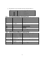
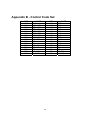
Appendix B - Control Code Set
HEX
00H
01H
02H
03H
04H
05H
06H
07H
08H
09H
0AH
0BH
0CH
0DH
0EH
0FH
CODE
NULL
SOH, MD1
STX, MD2
ETX, MD3
EOT, MD4
ENQ, MD5
ACK, MD6
BEL, MD7
BS, MD8
HT
LF
VT, HOM
FF, CLR
CR
SO, SLE1
SI, SLE2
HEX
10H
11H
12H
13H
14H
15H
16H
17H
18H
19H
1AH
1BH
1CH
1DH
1EH
1FH
48
CODE
DLE
DC1
DC2
DC3
DC4
NAK
SYN
ETB
CAN
EM
SUB
ESC
FS
GS
RS, SF1
US, SF2