1
Copyright ELECTROINVENT
Installation and User Manual
for AC vector control frequency inverters ELDI / V
(Revision NEW)
Version 1.00
Copyright ELECTROINVENT
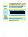
Contents
1
2
3
4
5
6
7
8
9
Introduction ........................................................................................................... 5
1.1 Disclaimer ..................................................................................................... 5
1.2 IMPORTANT SAFETY INSTRUCTIONS ..................................................... 6
1.3 Check for damages ...................................................................................... 6
1.4 Completeness by delivery of frequency inverters ELDI/V ............................ 6
1.5 Checking the type, label and serial number of the product .......................... 7
Warnings and Notes ............................................................................................. 8
General description of the product .................................................................... 9
3.1 Main technical parameters of frequency inverters - type ELDI / V ............... 9
3.2 Operation conditions .................................................................................. 10
3.3 Transport and storage ................................................................................ 11
3.4 Order code ................................................................................................. 11
Mechanical installation ...................................................................................... 12
4.1 Common requirements during installation.................................................. 12
4.2 Minimal distances and cooling ................................................................... 13
4.3 Overall and mounting dimensions .............................................................. 14
Connection of power terminals ......................................................................... 15
5.1 Connection of external devices to power terminals ................................... 15
5.2 Protective grounding of the inverter ........................................................... 15
5.3 Description of power terminals ................................................................... 17
5.4 Cross-section of cables for connection to power terminals........................ 19
5.5 Installation of defect current protection ...................................................... 20
5.6 Installation of starting contactor ................................................................. 20
5.7 Installation of input three-phase coke ........................................................ 21
5.8 Connection of brake resistor ...................................................................... 21
5.8.1
Choise of brake resistor .............................................................. 22
Electromagnetic compatibillity ......................................................................... 24
6.1 Actions to ensure electromagnetic compatibility ........................................ 24
6.2 Performance of cable connections ............................................................. 24
6.3 Shielding of connecting cables ................................................................... 25
Connecting of control connectors .................................................................... 27
7.1 Distribution of input-output control interface............................................... 27
7.2 Description of input-output connectors on control PCB ............................. 27
7.3 Connection of digital inputs ........................................................................ 30
7.3.1
General requirements to wiring ................................................... 30
7.3.2
Описание на цифровите входове ............................................ 30
7.4 Connection of analog inputs ....................................................................... 31
7.4.1
General requirements ................................................................. 31
7.4.2
Connection of analog inputs ....................................................... 31
7.4.3
Connecting cables and cable terminals ...................................... 32
7.4.4
Description of analog inputs ....................................................... 32
7.5 Interface for speed and position feedback ................................................. 33
7.5.1
Standard interface for feedback (terminals CN3) ....................... 33
7.5.2
Extended interface for speed and position feedback (connector
CN3D) ......................................................................................... 33
7.5.3
Supported interfaces ................................................................... 34
7.6 Multifunctional outputs................................................................................ 34
7.7 Series communication interface ................................................................. 35
7.7.1
Series communication interface for connection with PC ............ 35
7.7.2
Series communication interface for connection with PLC .......... 36
Running into exploitation .................................................................................. 37
8.1 Operator’s panel - description .................................................................... 37
8.2 Types of parameters .................................................................................. 37
8.3 Visualisation mode ..................................................................................... 37
8.4 Adjustment mode ....................................................................................... 38
8.5 Correction mode of parameter type „control word” .................................... 38
8.6 Examples of operating with keyboard ........................................................ 39
Parameters of frequency inverter (version V8) ............................................... 40
9.1 Menu 0 ( A ) - Speed reference .................................................................. 40
Manual ELDI / V (Revision NEW)
3/73
IUM ELDI/V ENG V1.00 0515
Copyright ELECTROINVENT
9.2
9.3
9.4
Menu 1 ( b ) - Visualization......................................................................... 41
Menu 2 ( C ) - Parameters of the motor ..................................................... 41
Меню 3 ( d ) - General adjustments ........................................................... 42
9.4.1
General adjustments - detailed description ................................ 43
9.5 Menu 4 ( Е ) - Multifunctional inputs ........................................................... 52
9.5.1
Polarity of multifunctional inputs ................................................. 53
9.5.2
Using the fast digital inputs ......................................................... 54
9.5.3
Functions of digital inputs – detailed description ........................ 55
9.5.4
Functions for analog inputs – detailed description ..................... 58
9.6 Menu 5 ( F ) - Multifunctional outputs ......................................................... 59
9.6.1
Polarity of digital outputs ............................................................. 60
9.6.2
Functions of digital outputs – detailed description ...................... 60
9.6.3
Functions of analog outputs – detailed description .................... 62
9.7 Menu 6 ( g ) - Configuring of analog inputs ................................................ 63
9.8 Menu 7 ( H ) - Temp of acceleration and braking ...................................... 63
9.9 Menu 8 ( I ) - Current limit .......................................................................... 64
9.10 Menu 9 ( J ) - Speed regulator ................................................................... 64
9.11 Menu 10 ( L ) - Vector control .................................................................... 65
9.12 Menu 11 ( n ) - Configuring Start / Stop mode ........................................... 65
9.13 Menu 12 ( o ) - Communication .................................................................. 66
9.14 Menu 13 ( P ) - Parameters of curve U/F ................................................... 66
9.15 Menu 14 ( q ) - Configuring DC brake ........................................................ 67
9.16 Menu 15 ( r ) - Pump control ...................................................................... 67
10 MODBUS communication .................................................................................. 68
10.1 Supported functions of MODBUS protocol ................................................. 68
10.2 Addressing parameters and variables of the drive by MODBUS protocol . 68
10.3 Addressing principle ................................................................................... 68
10.4 Addressing of parameters for visualization of drive's variables ................. 68
10.5 Addressing of parameters for drive's control .............................................. 69
10.6 Reading of parameters for visualization through series port...................... 69
10.7 Operation with specialized menu for control of the drive ........................... 70
10.8 Format of drive's parameters and variables, accessible by MODBUS ...... 70
11 Technical maintenance ...................................................................................... 71
11.1 Electronic protection of inverter .................................................................. 71
Description of inverter protections ........................................................................ 71
12 EC Declaration of conformity ............................................................................ 72
Contacts ...................................................................................................................... 73
Manual ELDI / V (Revision NEW)
4/73
IUM ELDI/V ENG V1.00 0515
Copyright ELECTROINVENT
1
Introduction
Transistorized frequency inverters series ELDI / V are intended to control the speed of
standard 3-phase asynchronous and synchronous motors. They work on the principal of
double conversion of electrical energy AC-DC-AC, by which the motor is supplied with
controlled by frequency and amplitude 3-phase voltage. The frequency inverters are
realized by using up-to-date electronic basis with high level of integration, power
intelligent IGBT modules in the power part and high-productivity specialized DSP in the
control part. They have possibility for parameters’ adjustment of the inverter depending
on the type and parameters of the controlled motor and on the specific requirements to
the mechanical device, which will be driven.
The speed control of the motor becomes by regulation of the output voltage, as well as by
output frequency regulation.
The inverters’ range is developed for the following voltages and powers of the electrical
motor:
200 - 230V 1 ~ 50/60Hz – for motors with power 0,55kW to 2,2кW
380 - 400V 3 ~ 50/60Hz – for motors with power 0,55kW to 75кW
1.1
Disclaimer
ELECTROINVENT delivers optimized and tested equipment like Inverters and string
boxes for Solar Power Plants. The correct integration and interconnection of the
equipment according to the manuals and datasheets from ELECTROINVENT is the
responsibility of the System Integrator. ELECTROINVENT does not assume any
liability for system design, dimensioning, build-up and the performance of the
system. Claims because of downtime are excluded.
The contents of the written text are reviewed for compliance with the hardware and
software described below. However, inaccuracies cannot be excluded, thus preventing us
from supplying a full warranty for full compliance. The data supplied in the current manual
is reviewed regularly. Corrections are included in subsequent editions.
In case of violation of the installation instructions warranty claims will not be accepted.
We discard any liability in cases of accidents and material damage, caused by
inappropriate handling, undertaking of works by unauthorized personnel and the resulting
damages on persons and device, as well as for any resulting subsequent damages.
Manual ELDI / V (Revision NEW)
5/73
IUM ELDI/V ENG V1.00 0515
Copyright ELECTROINVENT
1.2
IMPORTANT SAFETY INSTRUCTIONS
READ AND SAVE THESE INSTRUCTIONS!
This manual contains important safety and operating instructions for ELDI / V
inverter. Keep it with or near the inverter at all times.
AC vector control frequency inverters operate with lethal voltages and the work described
here should only be performed by authorized personnel familiar with the installation,
mounting, commissioning, and the operation of AC vector control inverters. This manual
must be fully read and understood before installing or commissioning is performed. The
ELDI / V product must only be used for its intended purpose and unauthorized personnel
are not allowed to open the ELDI / V product. The faultless and safe operation of the
product assumes appropriate transport, correct storage, installation and mounting as well
as correct operation and maintenance. The relevant regional and country-specific
regulations and instructions must be obeyed as well as requirements described in this
document including placement and installation instructions (e.g. connection profiles,
torque settings, etc.)
Symbols and warning signs used:
WARNING
WARNING indicates a hazardous situation which, if not avoided, could result in death
or serious injury.
ATTENTION
ATTENTION refers to address practices not related to personal injury. Failure to
observe could lead to property damage.
1.3
Check for damages
Check the drive for eventual damage during transportation. If it has damaged or noncorresponding parts, please inform the producer – “Electroinvent” Ltd or the distributor,
from whom you have purchased the product.
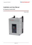
1.4
Completeness by delivery of frequency inverters ELDI/V
Q-ty:
Article:
1 pc.
Frequency inverter ELDI / V
1 pc.
Connector type CTF1600T, 16 pins - (CN2)
1 pc.
Connector type CTF0800T, 8 pins - (CN3) / or type HD-15 FM, 15 pins
(CN3D)
1 pc.
Installation and user manual
Manual ELDI / V (Revision NEW)
6/73
IUM ELDI/V ENG V1.00 0515
Copyright ELECTROINVENT
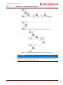
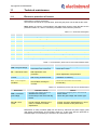
1.5
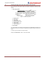
Checking the type, label and serial number of the product
Check if the type of the product, written on the lable, corresponds to model you have
ordered.
Label of the product
1
2
3
6
7
4
5
8
Figure 1.1. Label of the product
1.
2.
3.
4.
5.
6.
7.
8.
Product’s mod;
Motor power;
Input voltage;
Nominal input current;
Maximal allowed current;
Output voltage;
Nominal output current;
Output frequency;
Serial number
The series number of the product is unique and serves for identification and follow-up of
the concrete product by its production, programming, parameter setting, purchase and
service.
It consists of year of production and series number.
Example: Serial No151027 - 2015г., series number 1027.
Manual ELDI / V (Revision NEW)
7/73
IUM ELDI/V ENG V1.00 0515
Copyright ELECTROINVENT
2
Warnings and Notes
WARNING
The local installation standards must be obeyed.
WARNING
The device must only be installed, operated and maintained by qualified personnel.
WARNING
The device carries lethal grid voltages. Consider a capacitor discharge time of 10
minutes, before starting assembly or disassembly the power output terminals.
WARNING
Consider all safety instructions displayed on the inverter and in the installation and
user manual!
WARNING
ATTENTION!
Danger from burning! Heatsink can be hot!
WARNING
If any information is unclear, please refer to ELECTROINVENT.
ATTENTION
Loss of warranty.
The frequency inverter must not be damaged and no holes are allowed to be drilled in
the cabinet. Any transport damage must be reported to ELECTROINVENT.
Manual ELDI / V (Revision NEW)
8/73
IUM ELDI/V ENG V1.00 0515
Copyright ELECTROINVENT
3
General description of the product
3.1
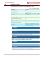
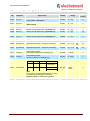
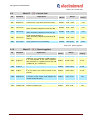
Main technical parameters of frequency inverters - type ELDI / V
Table 3.1. Technical parameters of ELDI / V-A and ELDI / V-B
Type
Dim.
Motor power
kW
Input voltage
VAC
Frequency of UIN
Hz
Input current
A
ELDI / V-A
0,55
0,75
1,1
ELDI / V-B
1,5
2,2
0,55
0,75
1,1
200 ÷ 230 V1~ ± 10%
1,5
2,2
4,0
5,5
50 / 60 ± 5%
5,3
7,6
10,2
13,5
18
2,1
2,9
4,2
5,1
6,5
9,2
12,5
16,0
4,2
6,0
7,6
10,2
11,2
110
135
155
180
180
Output voltage
VAC
3 x 0 ÷ Usupp.
Output frequency
Hz
0,1 ÷ 400 (by customer’s request - 512)
Output current
A
Max.current (60s.)
A
Dissipated power
W
Pulse current by dynamic
braking
A
3,0
4,3
5,9
7,1
9,5
2,0
2,3
3,2
150% IH once at 10 minutes
48
55
65
85
110
40
52
80
6
Natural
(convection)
Cooling type
3,0
380 ÷ 400 V3~ ± 10%
8
Forced (fan)
10
Natural (convection)
Forced (fan)
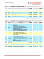
Table 3.2. Technical parameters of ELDI / V-DF and ELDI / V-D
Type
Dim.
Motor power
kW
Input voltage
VAC
Frequency of UIN
Hz
Input current
A
Output voltage
VAC
Output frequency
Hz
Output current
A
Max.current (60s.)
A
Dissipated power
W
Pulse current by dynamic
braking
A
ELDI / VDF
7,5
11
15
18,5
22
30
37
45
55
75
94
112
125
175
105
138
380 V3~ ± 10%
50 / 60 ± 5%
21,5
32
43
53
62
82
3 x 0 ÷ Usupp.
0,1 ÷ 400 (by customer’s request - 512)
16
22
29
150% IH
270
450
20
Cooling type
Manual ELDI / V (Revision NEW)
ELDI / DF
36
42
62
140% IH
550
680
720
72
85
130% IH
840
30
920
1100
40
120% IH
1300
1500
60
100
Forced (fan)
9/73
IUM ELDI/V ENG V1.00 0515
Copyright ELECTROINVENT
3.2
Operation conditions
The operation conditions of frequency inverters are described in Table 3.3.
Table 3.3. Operation conditions
Parameters:
Condition:
Degree of protection
IP20
Operating temperature
from +5°С to +45°С
Air humidity
maximum
80%
condensation)
Altitude
up to 2000m
Overvoltage category
III
Pollution degree (for environment)
2
Protection class against electrical current
injuries
I
Type of electrical supply system
TN
Environment
explosion proof, without current conducting
parts, gases and vapours in concentration
with destructive influence
at
o
30 С
(without
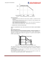
ATTENTION
Nominal output power is decreased with 1% at each 100m at installations in
environment above 1000m.
ATTENTION
If the surrounding temperature of the AC drive is above 45°C, install it better at
ventilated place, without obstruction of the air flow of cooling fan.
ATTENTION
To increase the reliability, the inverter has to be installed at place, protected from high
temperature. If the inverter is installed in a cabinet, use cooling fan or air conditioner,
o
with aim to keep surrounding temperature not higher than 45 С.
ATTENTION
Pay attention to vibrations and check if they influence to electrical devices in the
cabinet.
ATTENTION
Inverter and motor radiate heating. It is necessary to secure enough distance between
inverter and other devices in the cabinet, the heat to be dissipated.
Manual ELDI / V (Revision NEW)
10/73
IUM ELDI/V ENG V1.00 0515
Copyright ELECTROINVENT
Observe the following rules when choose the place for installation:
Don’t install inverter near heat-radiating elements or directly to sun shine;
Don’t install at place, exposed to corrosive gases, liquids, dust in the air or metal
micro parts;
Don’t install at places, where the temperature and humidity exceed the specified;
Don’t install inverter at places, where it will be exposed at high level of
electromagnetic radiation.
ATTENTION
If you don’t observe these requirements, you can lose your guarantee!
3.3
Transport and storage
The conditions for transport and storage are describe below:
Environment temperature: -20 С to +65 С
Air humidity: from 0% to 90% (without condensation of moisture)
The inverters to be not submitted to influence of shocks, vibrations, UV radiation,
etc.
The inverters to be stored in dry and clean premises, without direct sun shine
The inverters to be stored in premises without presence of corrosive gases and
liquids, packed well and placed on solid surface
The inverters to be stored in transport packing before their installation.
o
o
To keep the guarantee, the inverters must be stored correctly.
3.4
Order code
ELDI/V
-
X(X)
-
Series
-
Version
-
ELDI/V
A
B
DF
D
Table 3.4. Order code of frequency inverters ELDI / V
X
XX.X
X
Power supply
- Motor power in kW Feedback
Number of
Voltage
phases
Open (без)
1
2
00.5
0.5kW
O
230V
Еncoder
3
4
00.7
0.7kW
E
400V
enDat
…
…
D
SSI
75.0
75kW
S
X
Example:
ELDI/V-B-34-02.2-E is the code of inverter with vector control, version B, 3-phase supply
380-400V, for motors up to 2,2kW and feedback from standard encoder.
Manual ELDI / V (Revision NEW)
11/73
IUM ELDI/V ENG V1.00 0515
Copyright ELECTROINVENT
4
Mechanical installation
4.1
Common requirements during installation
By installation of frequency inverters must be observed the following requirements:
By installation unpack carefully and take out the inverter from the packing.
Install the frequency inverters ELDI / V in the electrical cabinet.
Install the inverter on mounting surface with enough strength and rigidness.
Install the inverter on uninflammable surface.
Install the inverter with suitable fixing elements, using instruments, guaranteeing the
needed force for mechanical fixing.
Install the inverter in this way, that the acces to it to be guaranteed during operation,
adjustment and maintenance.
Don’t bend and strain connecting cables between inverter and motor.
Frequency inverters ELDI/V are intended to work with electrical motors, in conformity
with requirements of IEC60034-1.
Sensors mounted on the motors and connected to frequency inverters must have
secured during installation double and/or strengthened insulation between them and
current conducting parts of the motor, as well as additional insulation between them
and the accessible current conducting parts of the motor. The insulations must
secure operation of the for working voltage 400VAC.
If the length of the cable between inverter and motor is more than 20m, increase the
cross section of power cable, connecting motor and inverter, as well as the cable for
connecting the encoder.
Check if the motor fixing screws are tightened well.
Manual ELDI / V (Revision NEW)
12/73
IUM ELDI/V ENG V1.00 0515
Copyright ELECTROINVENT
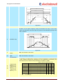
4.2
Minimal distances and cooling
ATTENTION
Incorrect installation can cause prematurely damage of inverter. Follow instructions of
this manual during installation of the inverter.
The inverter must be istalled perpendicularly to the wall of the cabinet or to the
control panel.
To secure good ventilation, check if all ventilation outlets are free and if there is
enough space around them.
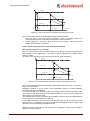
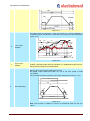
Don’t mount the inverter in horizontal position, because it will make worse cooling
and can bring to damage (Figure 4.1).
Figure 4.1. Mounting the inverter
The inverter must be mounted vertically with its back to the wall, on dry and hard
surface.
To be left minimum 100mm distance above and bellow it to secure ventilation and
heat dissipation.
Install a fan to avoid ambient temperatures, higher than specified.
When you install two and more inverters, keep the minimal distancies between them
(Figure 4.2).
Figure 4.2. Minimal distances
Manual ELDI / V (Revision NEW)
13/73
IUM ELDI/V ENG V1.00 0515
Copyright ELECTROINVENT
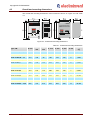
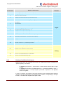
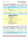
4.3
Overall and mounting dimensions
The overall and mounting dimensions of the inverter are shown on Figure 4.3 and Table
4.1.
Figure 4.3. Overall and mounting dimensions
Table 4.1. Overall and mounting dimensions
H, mm
Wmax,
mm
Dmax,
mm
C, mm
h, mm
w, mm
d, mm
Weight,
kg
ELDI / V-A 0,55 - 0,75
210
128
92
180
195
105
6
1,800
ELDI / V-A 1,1 - 2,2
210
128
140
180
195
105
6
2,150
ELDI / V-B 0,55 – 1,1
210
128
92
180
195
105
6
1,800
ELDI / V-B 1,5 – 2,2
210
128
140
215
195
105
6
2,150
ELDI / V-B 3,0
245
128
140
215
230
105
6
2,650
ELDI / V-B 4,0 – 5,5
280
128
140
250
265
105
6
3,050
ELDI / V-DF 7,5 –11,0
340
180
185
300
320
140
7
7,350
ELDI / V-D 15,0
310
215
175
280
195
180
7
8,800
ELDI / V-D 18,5 – 22,0
410
275
250
370
390
235
9
17,550
ELDI / V-D 30,0
410
275
250
370
390
235
9
19,000
ELDI / V-D 37,0
655
315
270
575
620
260
13
32,100
ELDI / V-D 45,0
655
315
270
575
620
260
13
36,600
ELDI / V-D 55,0 – 75,0
655
315
270
575
620
260
13
39,400
Type, kW
Manual ELDI / V (Revision NEW)
14/73
IUM ELDI/V ENG V1.00 0515
Copyright ELECTROINVENT
5
Connection of power terminals
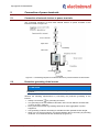
5.1
Connection of external devices to power terminals
The connecting sequence of most used external devices to power terminals of the
inverter is shown on Figure 5.1.
Figure 5.1. Connecting sequence of external devices to power terminals of the inverter
5.2
Protective grounding of the inverter
ATTENTION
Protective grounding is used to lead away the leakage current from inverter’s corpus
to ground.
Observe the following requirements by connecting the protective grounding of the
inverter:
Always use terminal
for grounding of inverter;
The grounding to be with resistance less than 100 Ω for net 200VAC and less than
10 Ω for net 380 - 420VAC;
Don’t ground the inverter to grounding terminals of other aggregates or power
equipment;
Use grounding conductor according to standard and with possible shorter length;
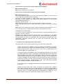
When you use several inverters, pay special attention about connecting of grounding
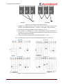
conductor. It is not allowed to form closed loop (Figure 5.2);
Manual ELDI / V (Revision NEW)
15/73
IUM ELDI/V ENG V1.00 0515
Copyright ELECTROINVENT
Correct
Incorrect
Figure 5.2. Connecting of grounding conductor
Between the output terminals of the inverter and the motor there must must not
have any commutation apparatuses - contactor, circuit braker, relay and others!
Do not connect the power supply to output terminals U, V, W !
The inverters are designed for 3-phase asynchronous motors connected in a
scheme where there is correspondence between the supply voltage of the motor
and output voltage of the inverter!
Do not connect the neutral phase to the output terminals U, V, W !
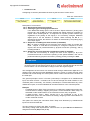
The connecting of the power terminals of series ELDI / V are shown on Figure 5.3.
ELDI/V-A
ELDI/V-B
ELDI/V-DF
ELDI/V-D
Figure 5.3. Connecting the power terminals of series ELDI / V
Manual ELDI / V (Revision NEW)
16/73
IUM ELDI/V ENG V1.00 0515
Copyright ELECTROINVENT
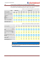
5.3
Description of power terminals
In Table 5.1. are shown the description of power terminals of frequency inverters.
Table 5.1. Description of power terminals
Symbol:
Explanation:
Function:
Mains supply
About inverter’s supply from electrical net.
By 1-phase supply, connect L1 and L2(N) (200-240VAC).
By 3-phase supply, connect L1, L2 and L3 (380-400 VAC).
Functional
grounding
It is used for functional grounding of inverter to grounding bolt of
the electrical cabinet or to protective loop of building installation.
Protective
grounding
About protective grounding of inverter’s corpus.
U, V, W
Motor supply
About connection between inverter and motor.
Rb, Rb
External resistor
About connection of external brake resistor.
L1, L2, L3
For trouble-free operation of the frequency inverter it is necessary to observe the
following requirements about wiring of power terminals:
All used connectors are executed in accordance with requirements for protective
split.
The connecting terminals of inverter are not intended for disconnection under load.
Check about correct connection of power net supply (L1, L2, L3).
Check about correct connection of protective grounding of inverter with grounding
bolt of the cabinet or to protective loop of building installation.
Check about correct connection of the motor to connector (U, V, W).
Check about correct connection of protective grounding of the motor to grounding
bolt of the drive.
Pay attention during installation, operation and maintenance, that power terminals of
power circuits appear parts under dangerous voltage and additional measures must
be taken for trouble-free operation with them or very close operation to them.
DANGER
After switch-off of power voltage, it is necessary to wait minimum 10 minutes before
starting assembling or disassembling of power input and output connectors/terminals.
The time is needed to discharge the capacitor battery in power unit.
Manual ELDI / V (Revision NEW)
17/73
IUM ELDI/V ENG V1.00 0515
Copyright ELECTROINVENT
Power cables (L1, L2, L3, U, V, W) to be placed in cable duct separately from signal
cables of input output interface and encoder.
Use connecting cables with cross sections shown in Table 5.2. and Table 5.3.
Use cables with double insulation only, conformable with operating voltages of the
system (for example type HOSVV-F or type HO5RR-F).
For connections about protective grounding use only yellow/green cables with
double insulation, conformable with operating voltages of the system (for example
type HOSVV-F or type HO5RR-F).
The temperature contact sensors built in the motor can be connected to the
programmable digital input of frequency inverter, which will switch-off the inverter,
when thermo-protection of the motor is switched-on.
Special protective measures are taken regarding accessible circuits for control,
working at trouble free over-low voltage (SELV). These measures include protective
splitting of all control circuits from the power high voltage circuits by means of double
and strengthened insulation, calculated for over-voltage category III and maximal
operating voltages 400V or 230V in the units.
It is necessary the protective splitting to be preserved during installation, operation
and maintenance by means of suitable splitting of power and control circuits , using
cables and connectors with appropriate double and strengthened insulation and
observing the specified climatic and thermal requirements.
ATTENTION
Don’t connect power supply to output terminals U, V, W!
Don’t connect “neutral (0)” to output terminals U, V, W!
Never use capacitor as filter against disturbances, connected to output terminals
U, V, W! The high output frequency can overheat it, to destroy the capacitor or
inverter to destroy itselve.
Manual ELDI / V (Revision NEW)
18/73
IUM ELDI/V ENG V1.00 0515
Copyright ELECTROINVENT
5.4
Cross-section of cables for connection to power terminals
When performing wiring diagrams of the power terminal must to meet the requirements
for the section of the connecting cables shown in Table 5.2. and Table 5.3.
Table 5.2. Cross-section of cables for power terminals
Type
Power [P], kW
Input - L1, L2, L3, mm
ELDI / V-A
0,55
0,75
1,1
1,5
2,2
0,55
0,75
1,1
1,5
2,2
3,0
4,0
5,5
1
1,5
2,5
0,75
1
1
1,5
1,5
2,5
2,5
4
1
1,5
2,5
0,75
1
1
1,5
1,5
2,5
2,5
4
1
1
2,5
0,75
1
1
1,5
1,5
2,5
2,5
4
1
1,5
2,5
0,75
1
1
1,5
1,5
2,5
2,5
4
1
1,5
2,5
0,75
1
1
1,5
1,5
2,5
2,5
4
2
Functional grounding
2
, mm
Protective grounding
, mm
ELDI / V-B
2
Output connecting the
2
motor - U, V, W, mm
Protective grounding
2
of the motor, mm
Table 5.3. Cross-section of cables for power terminals
Type
ELDI / V-DF
ELDI / V-D
7,5
11,0
15,0
18,5
22,0
30,0
37,0
45,0
55,0
75,0
4
6
6
10
16
25
25
35
35
50
4
6
6
10
16
25
25
35
35
50
-
-
-
1,5
1,5
1,5
1,5
1,5
1,5
1,5
4
6
6
10
16
25
25
35
35
50
Connecting the motor - U, V,
2
W, mm
4
6
6
10
16
25
25
35
35
50
Protective grounding of the
2
motor, mm
4
6
6
10
16
25
25
35
35
50
Short circuit current of input
automat type „С”, А
-
-
63
63
100
100
125
125
150
200
Power [P], kW
Input - L1, L2, L3, mm
2
Functional grounding
2
mm
,
Operating neutral [N], mm
2
Functional grounding
2
mm
,
ATTENTION
The scheme is for 5-conductors supply grid (3P+PE+N).
If the supply grid is 4-conductors scheme (3P+ PE /protective grounding), please refer
for information to producer.
Manual ELDI / V (Revision NEW)
19/73
IUM ELDI/V ENG V1.00 0515
Copyright ELECTROINVENT
5.5
Installation of defect current protection
Output voltage U, V and W supplying the motor is PWM modulated with high frequency. It
causes high frequency leakage to the corpus, which can be dangerous to the personel.
This is the reason the inverter corpus to be through automat for protection from leakages.
Note: When you use special automat for protection from leakage – choose with current
sensibility minimum 30mA per inverter.
When you use ordinary automat for protection from leakage – choose with current
sensibility 200mA per inverter and reaction time 0,1s.
5.6
Installation of starting contactor
Starting contactor for power supply L1, L2, L3 is mounted, when there is requirement for
remote switch-off of inverter from the supplying grid by emergency cases.
The inverter can be switche-on and switched-off from contactor by specified
adjustments.
Secondery starting of the inverter through contactor, switching-on the power supply,
must be done when the motor is stopped. If this requirement is not fulfilled, it is
possible to cause damage in it. In this case it is necessary to increase the waiting
time by switching-on through parameter n.05 “Timer for prohibition secondary
starting “.
Always use RC-groups or diodes to extinguish the reactive energy in starting
contactor coils, relays, magnet switches and similar equipment, being inductive
loads, when they are mounted near inverter.
Don’t use contactor for switch-on and switch-off the motor to output terminals U,V,W
of the inverter during operation. If contactor switches-on the motor, when the inverter
is activated (it has output frequency and voltage), the overload protection can be
activated or the motor can be destroyed.
When it is necessary to use contactor for switching-off the motor from output
terminals U,V, W, it must be done when inverter is stopped – there is no voltage at
the output terminals.
It should be known, that by switch-off of starting contactor, the motor will stop by
inertia.
Manual ELDI / V (Revision NEW)
20/73
IUM ELDI/V ENG V1.00 0515
Copyright ELECTROINVENT
5.7
Installation of input three-phase coke
For inverters with power 15kW to 75kW, with aim to protect the supplying grid from
entering of high frequency harmonics and to decrease them, it is necessary to use input
3-phase choke. It improves the operation of the rectifying unit and prolongs the life of
electrolytic capacitors in the inverter. Overall and fixing dimensions of input chokes, used
for inverters ELDI/V-D 15- 75kW, are shown in attached Table 5.4:
Table 5.4. Overall and mounting dimensions of input coke
Type
Rated current, А
Rated power,
kW
Induction, mH
A,
mm
B,
mm
H,
mm
a,
mm
b,
mm
Weight,
kg
РК 02612
60
15 - 18,5
0,2
180
125
190
140
82
8
РК 02715
75
22 - 30
0,2
180
125
190
140
82
8
РК 021320
130
37
0,2
250
180
170
180
82
8,6
РК 021632
160
45 - 55
0,2
250
200
170
180
82
8,9
РК 022550
250
75
0,2
270
212
180
180
82
9,5
Figure 5.4. Overall and mounting dimensions of three-phase coke
5.8
Connection of brake resistor
Brake resistor is used to extinguish the breaking energy during fast stop or revers of the
motor, when it drives mechanism with big inertion mass. The recommended values of
resistor and its power are given in Table 5.5.
Table 5.5. Recommended values
Type
ELDI / V-A
ELDI / V-B, ELDI / V-DF
ELDI / V-D
0,551,1
1,52,2
0,551,5
2,24,0
5,5 7,5
11
15
18,5
22
37
45
55
75
Brake resistor, Ω
100
50
100
100
70
50
30
30
30
25
20
20
15
Power of
resistor, W
80 100
100
150
250
350
550
400
450
450
1020
1200
1400
2500
Moment power
of resistor, kW
0,75
1,0
1,5
2,5
3,5
5,5
17,5
17,5
17,5
21
24,5
24,5
35
Pulse current at
the output of
inverter, А
10
20
10
20
25
30
30
30
30
50
50
50
75
Cross-section of
connecting
cables, mm2
0,75
1
1,5
2,5
2,5
2,5
2,5
2,5
2,5
6
6
10
16
Power of
inverter, kW
During stop at terminals Rb the voltage can reach up to 780VDC. The necessary
insulation distancies must be secured when mounting the resistor.
Manual ELDI / V (Revision NEW)
21/73
IUM ELDI/V ENG V1.00 0515
Copyright ELECTROINVENT
DANGER
After switch-off of supplying voltage it is necessary to wait minimum 10 minutes until
start assembling or disassembling of connecting cables at power terminals Rb.
ATTENTION
It is necessary to secure enough distance between frequency inverters, brake resistor
and other equipment in the cabinet, to dissipate the heat.
Take care of additional cooling of brake resistor and other equipment in the cabinet.
5.8.1
Choise of brake resistor
In Table 5.6. are shown brake resistors, suitable for frequency inverters ELDI / V series.
ELDI / V-А
ELDI / V-А
ELDI / V-А
ELDI / V-B
ELDI / V-B
ELDI / V-B
ELDI / V-DF
ELDI / V-D
Inverter power,
kW
0,55
0,75 - 1,1
1,5 – 2,2
0,55 – 1,1
1,5 to 3,0
4,0 to 7,5
11
15 to 22
ELDI / V-D
30 to 37
ELDI / V-D
45 to 55
Inverter type
Table 5.6. Suitable brake resistors for ELDI / V series
Model brake resistor
Resistor
Resistance, Ω
MITSUBISHI
power, W
FR-ABR-04K
200
60
FR-ABR-0.75K
100
80
FR-ABR-H2,2K
60
100
FR-ABR-H1,5K/2,2K/3,7K
350/250/150
115-155
FR-ABR-H3,7K/5,5K
150/110
155-185
FR-ABR-H7,5K
75
340
FR-ABR-H11K
52
530
2ХFR-ABR-H7,5K in parallel
36
830
2 Х FR-ABR-H11K in parallel*
26
1060
3ХFR-ABR-H7,5К in parallel*
25
1020
3 Х FR-ABR-H11K in parallel*
18
1980
*Note: For bigger powers can be used resistors with lower power, connected in parallel.
The total value of received in parallel connection resistor must be not smaller than
specified in Table 5.6.
The permissible loading of brake resistors type FR-ABR and FR-ABR-H are shown in
Table 5.7.
Type
Permissible pulse loading
Permissible operation on cycle
Manual ELDI / V (Revision NEW)
FR-ABR (200V)
0,75k
2,2k
3,7k
100% / 5 sec.
10%
22/73
Table 5.7. Permissible loading of brake resistors
FR-ABR-H (400V)
0,75k
2,2k
3,7k
5,5k
7,5k
11k
100% / 5 sec.
10%
6%
IUM ELDI/V ENG V1.00 0515
Copyright ELECTROINVENT
Overall and mounting dimensions of brake resistor type FR-ABR and FR-ABR are shown
in Figure 5.5. and Table 5.8.
Figure 5.5. Overall and mounting dimensions of brake resistor from Table 5.8
Table 5.8. Overall and mounting dimensions of brake resistor
Dimensions, mm
Cable terminals, mm
Resistance, Ω
Brake resistor type
W
200V
W1
W2
D
А1
А2
H
FR-ABR-0,4K
140
125
100
40
21
200
FR-ABR-0,75K
215
200
175
40
21
100
FR-ABR-H1,5K
240
225
200
50
26
60
FR-ABR-H1,5K
215
200
175
40
21
350
FR-ABR-H2,2K
240
225
200
50
26
250
FR-ABR-H3,7K
215
200
175
61
33
150
FR-ABR-H5,5K
335
320
295
61
33
110
FR-ABR-H7,5K
400
385
360
80
40
75
FR-ABR-H11K
400
385
360
100
50
52
B1
d1
B1
d2
7.0
4.3
7.0
4.3
7.0
4.3
7.0
4.3
9.5
5,3
9.5
5,3
9.0
6,4
9.0
6,4
400V
Note: Use cables with double insulation only, in accordance with the system valtage (for
example type HOSVV-F or type HO5RR-F).
ATTENTION
It is not permissible to prolong the brake resistor cables longer than 5 m!
ATTENTION
The interruption or damage to the brake resistor during braking or during movement,
leading to activation of protection OSF (over voltage) and dropping the relay
"Ready“.The motor will stop by inertia (the mechanism shall continue to run). It is
necessary to take additional measures to safely stop the mechanism, if it is
dangerous.
Manual ELDI / V (Revision NEW)
23/73
IUM ELDI/V ENG V1.00 0515
Copyright ELECTROINVENT
6
Electromagnetic compatibillity
This manual is developed with aim to help the design of electrical mechanisms with use
of frequency inverters ELDI / V. In the manual are described the measures, which have to
taken to fulfill the conditions about electromagnetic compatibility. Instructions for mounting
and connection of frequency inverters, described in the manual, must be executed
exactly. They are obligatory and their correct execution will guarantee covering of EMC
standards. The frequency inverters have a certificate for electromagnetic compatibility by
standards EN 61800-3:1996, EN61000-3-2; A1, A2, A14:2000.
The electrical mechanisms, no matter what they are, create during operation
electromagnetic and radio disturbances at different frequencies. Cables radiate
electromagnetic and radio disturbances in surrounding environment. Connecting electrical
equipment (electrical motors, contactors, etc.) to the supplying grid, without use of input
filter, certainly will cause entering of high and low frequency disturbancies and harmonics
into supplying grid. They can cause malfunction of other equipment, supplied from the
grid.
6.1
Actions to ensure electromagnetic compatibility
The main counter actions against the disturbances are:
Splitting and galvanic disconnection of power from control circuits;
Reliable grounding and shielding;
The big contact surface of the contact by grounding is necessary to achieve low
resistance by grounding with aim to remove high frequency disturbances;
Use of grounding bars (or lamellae) instead of cables;
By grounding the cable’s shield must be connected to grounding bar with the help of
special cramps;
It is not possible to prescribe detailed and exact instructions, which can cover all possible
electrical equipment. For this reason, in this manual are discussed the common principles
only, by their observation the conditions about electromagnetic compatibility can be
reached.
6.2
Performance of cable connections
Measures to decrease the input disturbances from supplying grid:
The input grid filter and frequency inverter must be installed on common grounded
metal plate;
The grid filter and frequency inverter to installed possibly closer, to receive minimal
length of connecting cable;
Use shielded and grounded supplying cable;
Use shielded and grounded cable from inverter to motor with length no more than
20m;
Perform grounding this way, that the maximum contact surface of grounding terminal
to be received;
Install the inverter and other equipment in metal cabinet;
Manual ELDI / V (Revision NEW)
24/73
IUM ELDI/V ENG V1.00 0515
Copyright ELECTROINVENT
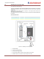
6.3
Shielding of connecting cables
Use cables with shield (sleeving).
Grounding of the shield to catch maximum possible surface of the sleeving. The sleeving
must not be interrupted. If there are intermediate connectors, they must be in grounded
metal boxes.
Special clamps to be used as shown on Figure 6.1. The clamps must be fixed on the
plate tightly, to have good contact.
The shield grounding of the cables has to be done to common bolt, marked with ‘РЕ’ near
the inverter.
Recommended filters:
Filter type
3MF-400/8
3MF-400/16
Current, (A)
8
16
Inverter power, kW
1,5kW to 3kW
4,0kW to 5,5kW
Figure 6.1. Shielding of connecting cables
1.
Grounding plate;
2.
Frequency inverter ELDI / V;
3.
Non-grounded supply cables;
4.
Non-grounded cables for outputs of relay contacts of the inverter;
5.
Shielded cable for connection of inverter output to the motor;
Manual ELDI / V (Revision NEW)
25/73
IUM ELDI/V ENG V1.00 0515
Copyright ELECTROINVENT
6.
Shielded cable for management and control. For applications, where is needed a big
2
number of cables, there must be used with small cross section (0,5mm ). The
sleeving must be grounded. The sleeving must be not interrupted, and if there are
intermediate connectors , they must be in grounded metal boxes.
7.
Shielded cable for connecting the brake resistor, if it is used.
8.
The fixing and connecting to ground of the shielded conductors 6, 7 and 8 are made
as close as possible to the frequency converter.
9.
Grounding screw.
10. Input EMC filter connected directly to the power supply with unshielded wire.
Note: In spite of grounding between frequency inverter, motor and sleeving of the cable,
it is necessary to connect the protective cables PE (yellow-green) to the appropriate
terminals of each device.
Manual ELDI / V (Revision NEW)
26/73
IUM ELDI/V ENG V1.00 0515
Copyright ELECTROINVENT
7
Connecting of control connectors
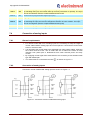
7.1
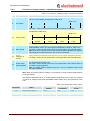
Distribution of input-output control interface
Input-output interface of inverters is distributed on 4 connectors on control board – CN1,
CN2, CN3 and CN4 as follows – see Figure 7.1.
Figure 7.1. Description of connectors on control board
7.2
Description of input-output connectors on control PCB
Table 7.1. CN1: Input-output interface (terminal type MKDS2-5.08)
CN1-1
RUN1
Multifunctional relay output RUN – normally open contact 1
CN1-2
RUN2
Multifunctional relay output RUN – normally open contact 2
Table 7.2. CN2: Input-output interface (terminal type CTF1600T)
CN2-1
COM
Common potential of digital inputs (+24V/ GND)
CN2-2
FL1
Multifunctional relay output – normally open contact 1
CN2-3
FL2
Multifunctional relay output – normally open contact 2
CN2-4
ON
Digital multifunctional programmable input
CN2-5
+10V
Stabilized supply voltage +10V
CN2-6
-AI1
Inverting input on differential analog input AI1
CN2-7
+AI1
Non-inverting input on differential analog input AI1
CN2-8
AGND
Analog ground
CN2-9
AI2U
Multifunctional analog/digital input AI2U
CN2-10
DI3
Multifunctional programmable digital input (fast)
CN2-11
DGND
Digital ground
CN2-12
F/R
Multifunctional programmable digital input
CN2-13
DI1
Multifunctional programmable digital input (fast)
CN2-14
DI2
Multifunctional programmable digital input
CN2-15
AO1
Multifunctional analog/digital input
CN2-16
AO2
Multifunctional analog/digital input
Manual ELDI / V (Revision NEW)
27/73
IUM ELDI/V ENG V1.00 0515
Copyright ELECTROINVENT
Table 7.3. CN3: Speed and possition feedback
(terminal type CTF0800T or connector HD-15 FM)
CN3-1
+5V
Stabilized supply voltage +5V 5V
CN3-2
DGND
Digital ground
CN3-3
A
Pulse sequence A
CN3-4
A\
Pulse sequence A – inverse signal
CN3-5
B
Pulse sequence B
CN3-6
B\
Pulse sequence B – inverse signal
CN3-7
Z
Zero pulse Z
CN3-8
Z\
Pulse sequence Z – inverse signal
Table 7.4. CN4: Series interface (connector type TS8P8C-PCB-S)
CN4-1
CAN_Rx
Not used
CN4-2
CAN_Tx
Not used
CN4-3
SS
Output – direction of communication Rx/Tx – “0” –receiving/”1”transmission
CN4-4
RS485_A/TxData
RS485_A or TxData – it is selected by switch S1
CN4-5
RS485_B/RxData
RS485_B or RxData – it is selected by switch S1
CN4-6
-
Not used
CN4-7
+5V
Stabilized supply voltage +5V
CN4-8
COM_RS485
Digital ground for communication
Manual ELDI / V (Revision NEW)
28/73
IUM ELDI/V ENG V1.00 0515
Copyright ELECTROINVENT
Figure 7.2. Frequency inverter ELDI-V – location of connectors on control board ELDI-CN
Figure 7.3. Control board ELDI-CN – connectors, micro-switches and jumpers
Manual ELDI / V (Revision NEW)
29/73
IUM ELDI/V ENG V1.00 0515
Copyright ELECTROINVENT
7.3
Connection of digital inputs
7.3.1
General requirements to wiring
For remote control with use of digital inputs it is necessary to keep the length of
control cable between control device and inverter, to be no more than 50m.
The cable to be separated from high voltage cables, supplying the inverter and the
motor. It is done to be reduced the effect of noise induction from power part or
disturbances from other power and relay circuits of external devices.
Описание на цифровите входове
7.3.2
Table 7.5. Digitals inputs – descriptions
Terminal
Name
Description
Common potential on digital inputs (+24V/ GND)
Depending on position of jumpers S2A and S2B, on this terminal is supplying +24V
(S2A and S2B in position 1-2) or GND (S2A and S2B in position 2-3) to digital inputs
S2A and S2B in position 1-2 (left) – the inputs are not galvanically untied and can be
activated in two ways:
- By connecting of common end of digital inputs to supplied to terminal CN2-1 voltage
+24V. See Figure 7.4.
- By supplying external voltage +24V to each input against DGND. See Figure 7.5.
Figure 7.4.
CN2-1
COM
Figure 7.5.
S2A and S2B in position 2-3 (right) – galvanically untied inputs type (see Figure 7.6.)
Figure 7.6
Manual ELDI / V (Revision NEW)
30/73
IUM ELDI/V ENG V1.00 0515
Copyright ELECTROINVENT
CN2-4
ON
Multifunctional programmable digital input. Factory adjustment – “Start of inverter” ON
By activating this input, the inverter starts (it receives permission to operate). The input
can be reconfigured. (See the chapter Multifunctional inputs)
CN2-10
DI3
Multifunctional programmable digital input (fast)
CN2-11
DGND
CN2-12
F/R
Multifunctional programmable digital input. Factory adjustment – Forward/Reverse [F/R]
By activating the input, the inverter changes the direction of motor rotation. The input
can be reconfigured. (See the chapter Multifunctional inputs)
CN2-13
DI1
Multifunctional programmable digital input (fast)
CN2-14
DI2
Multifunctional programmable digital input
Digital ground
7.4
Connection of analog inputs
7.4.1
General requirements
For remote control with use of analog inputs it is necessary to keep the length of
control cable between analog input and control panel or control device and inverter
to be no more than 50m.
It is necessary this control cable to be separated from high voltage cables, supplying
the inverter and the motor. This is made with aim to reduce the effect of noise
induction from power part or disturbances from other external power and relay
circuits.
By supplying control signal from external device it is necessary to use shielded cable
type with twisted pair.
The shield must be connected to terminal
7.4.2
, as shown on Figure 7.7.
Connection of analog inputs
Connection circuits of differential analog input are shown on Figure 7.7.
Figure 7.7. Connection circuits of differential analog input
Manual ELDI / V (Revision NEW)
31/73
IUM ELDI/V ENG V1.00 0515
Copyright ELECTROINVENT
7.4.3
Connecting cables and cable terminals
The size and type of shielded cable are shown in Table 7.6.
Terminal
type
Terminal
CN2-5 - +10V
CN2-6 - -AI1
CN2-7 -+AI1
CN2-8 --AGND
CN2-9 –AI2U
Table 7.6. Number of terminals and type of the cable
Recommended
Allowed cross-section of
cross-section,
Cable type
2
the cable, мм
2
мм
Shielded twisted pair
Single core 0,14 - 0,25
0,25
Multi core 0,14 - 0,75
0,55
0,5 - 1,5
1,25
CTF1600T
Shield
Shielded pair with
polyethylene
insulation with
external vinyl cover
Note: It is recommended to use cable terminals and roll-in instrument (without soldering)
with aim to simplify the connection and to increase the reliability.
7.4.4
Description of analog inputs
Terminal
CN2-5
Symbol
+10V
CN2-6
CN2-7
-AI1
+AI1
CN2-8
AGND
CN2-9
AI2U
Table 7.7. Description of analog inputs
Description
Stabilized power supply +10V
Differential analog input. Factory adjustment “Speed reference”. (0 to +/-10V)
By changing the voltage on this input, the output frequency will be controlled
(the revolutions of the motor). The direction of rotation is specified from the
polarity of analog voltage (+AI1 is non-inverting, and -AI1 is inverting input).
This input is multifunctional and can be reconfigured.
If analog signal is current (0 to 20mA), it is supplied to input “+AI1”, by
switching-on microswitch S3.2=ON.
Analog ground
Multifunctional analog/digital input AI2U.
The input signal can be:
Voltage from 0 to +10V – if microswitch S3.1 is OFF
Current from 0 to 20mA – ако microswitch S3.1 is in position ON
The input is multifunctional and can be reconfigured. It can be reconfigured as
analog or as digital.
Manual ELDI / V (Revision NEW)
32/73
IUM ELDI/V ENG V1.00 0515
Copyright ELECTROINVENT
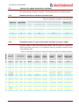
7.5
Interface for speed and position feedback
The control PCB is produced in 2 variants – with standard and with exstended interface.
7.5.1
Standard interface for feedback (terminals CN3)
Table 7.8. Description of signals on terminals CN3
CN3 pin#
Incremental encoder
Signal Name
SC (Sin_Cos)
Ab
Fd (Freq_Directin)
Fr (Forword_Reverse)
1
+5V
…
…
…
…
2
DGND
…
…
…
…
3
A
A
Freq
Forw
Cos
4
A\
A\
Freq\
Forw\
Cos\
5
B
B
Dir
Rev
Sin
6
B\
B\
Dir\
Rev\
Sin\
7
Z
Z
…
…
…
8
Z\
Z\
…
…
…
7.5.2
Extended interface for speed and position feedback (connector CN3D)
Connector CN3D is used for encoders with position code by control of synchronous
motors and precise servo drives. It is mounted as option (by customers request) instead
of terminal block CN3.
CN3 pin#
Table 7.9. Description of signals on connector CN3D for feedback by extended interface
ELDI-CN
Incremental
Commut.
Outputs
SinCos
Comutation
SC c
SinCos
encoder
Absolute
EnDat
Absolute
SSI
Stegmann 485
(HiperFace)
#
Signal
Ab
Fd
Fr
SErVO
SC
EndAt
SSI
HiPEr
1
+A_sin
A
Freq
Forw
…
Cos
…
…
…
2
-A_sin
A\
Freq\ Forw\
…
Cos\ref
…
…
…
3
+B_cos
B
Dir
Rev
…
Sin
…
…
…
4
-B_cos
B\
Dir\
Rev\
…
Sin\ref
…
…
…
5
+Z_enDat
Z
Z
Z
…
…
Data (in/out)
Data\(in)
Data\(in/out)
6
-Z_enDat
Z\
Z\
Z\
…
…
Data\ (in/out)
Data\(in)
Data\(in/out)
7
+U_sin
…
…
…
U
Sin
…
…
…
…
8
-U_sin
…
…
…
U\
Sin\
…
…
…
…
9
+V_cos
…
…
…
V
Cos
…
…
…
…
10
-V_cos
…
…
…
V\
Cos\
…
…
…
…
11
+W_enClck
…
…
…
W
…
Clock (out)
Clock (out)
-
12
W_enClck
…
…
…
W\
…
Clock\ (out)
Clock\ (out)
-
13
+5V
…
…
…
…
…
…
…
…
14
GND
…
…
…
…
…
…
…
…
…
…
…
…
…
…
…
…
15
Manual ELDI / V (Revision NEW)
33/73
IUM ELDI/V ENG V1.00 0515
Copyright ELECTROINVENT
7.5.3
Supported interfaces
Incremental encoder with and without zero pulse [A, A\, B, B\ and option Z, Z\] –
“Ab”.
Incremental encoder with pulse sequences for frequency and signal for direction with
and without zero pulse [Freq, Freq\, Dir, Dir\ and option Z, Z\] – “Fd”
Incremental encoder with pulse sequences for both directions with and without zero
pulse [Forw, Forw\, Rev, Rev\ and option Z, Z\] – “Fr”.
Encoder with additional UVW commutation signals [U, U\, V, V\, W, W\] –
“xx.SerVO”.
Encoder with additional sin and cos signals per revolution [Sin, Sin\, Cos, Cos\] –
additional option on STR-Vx1.
SinCos encoder – [Sin, Sinref, Cos, Cosref] – “SC.xxxxx”
Encoder with main or additional absolute sensor with SSI interface [Data (in), Data\
(in), Clock (out), Clock\ (out)] – “ SSI”
Encoder with additional Stegmann 485 (HiperFace) communication - [Data (in/out),
Data\ (in/out)] – “ xx.HiPEr”.
7.6
Multifunctional outputs
Table 7.10. Multifunctional outputs
Terminal
Symbol
CN1-1
CN1-2
RUN1
RUN2
CN2-2
CN2-3
CN2-15
CN2-16
Description
Multifunctional relay output RUN1- RUN2
Factory adjustment – Zero Speed
RUN1, RUN2 – normally opened
0,1A/220VAC.1А/30VDC.
contacts
of
relay
with
parameters:
FL1
FL2
FL1- FL2 Multifunctional relay output
Factory adjustment – Ready
On FL1, FL2 are brought-out the normally opened contacts of relay with parameters :
- 0,1A/110VAC 1А/30VDC.
When the inverter is supplied and there is no switched-on protection, the relay
contact is closed.
By absence of supply voltage, the contact is opened
AO1
Multifunctional analog/digital output АO1/DO1.
The type of output is choosen from position of microswitch S4.
Only one from the switches can be switched ‘ON’ !
S4-1:ON (S4-2:OFF) – on CN2-15 is brought-out digital output DO1, NPN, open
collector (0.5А/50VDC).
S4-2:ON (S4-1:OFF) – on CN2-15 is brough-out multifunctional analog output АO1,
with parameters: 0 to 20 mА or 4 mA to 20 mА.
AO2
Multifunctional analog/digital output АO2/DO2.
The type of the output is choosen from position of microswitch S5.
Only one from the switches can be switched ‘ON’ !
S5-1:ON (S5-2:OFF) – on CN2-16 is brought-out output DO2, NPN, open collector
(0.5А/50VDC).
S5-2:ON (S5-1:OFF) – on CN2-16 16 is brought-out multifunctional output АO2, with
parameters:
0 to 20 mА or 4 mA to 20 mА.
Note: If S2A and S2B in position 1-2 (jumpers on left), the digital inputs are not
optrone untiedand are from type NPN opened collector to DGND (CN2-10), as
shown on Figure 7.8.
If S2A and S2B are in position 2-3 (jumpers on right), the output are optrone untied
and they are NPN opened collector to COM (CN2-1), as shown on Figure 7.9.
Manual ELDI / V (Revision NEW)
34/73
IUM ELDI/V ENG V1.00 0515
Copyright ELECTROINVENT
Figure 7.8. Position 1-2 of S2A and S2B
Figure 7.9. Position 2-3 of S2A and S2B
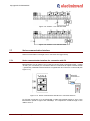
7.7
Series communication interface
Series communication is brought-out on connecter CN4 (type RJ45).
7.7.1
Series communication interface for connection with PC
Microswitches are as follows: S1A-1:‘ON’,S1A-2:‘OFF’,S1B-1:‘ON’,S1B-2:‘OFF’, jumper
J4:‘OFF’ (non connected). For connection with PC is offered as an option external module
– galvanically insulated RS-232 interface to signals RxD and TxD from control PCB (see
Figure 7.10).
Figure 7.10. Series communication interface for connection with PC
For RS-232 connection, it is recommended a cable with maximal length of 15m. If the
tramsmission speed is higher than 38400bps, it is required the maximal length of the
cable to be 3 m.
Manual ELDI / V (Revision NEW)
35/73
IUM ELDI/V ENG V1.00 0515
Copyright ELECTROINVENT
7.7.2
Series communication interface for connection with PLC
It is used standard Modbus RTU protocol by two-conductor RS-485 interface. In this case
micro-switches are as follows:
S1A-1:‘OFF’, S1A-2:‘ON’, S1B-1:‘OFF’, S1B-2:‘ON’and jumper J4:‘ON’ (set).
With jumper j5 can be included terminating resistor 120Ω, if necessary.
The switches must be respectively in one of the following 2 variants: (see Figure 7.11)
RS485
Figure 7.11. Series communication interface for connection with PLC
Figure 7.13. General view of switches and
terminals of communication connector
Figure 7.12. General view of control board
The general view of switches on control board ELDI-CN and the terminals of
communication connector are shown on Figure 7.12. and Figure 7.13.
For communication speeds up to 38400 bps in regime RS-485 the recommended
maximal length of the cable is 100m. If the speed of transmission is higher, the maximal
length of the cable is 15m.
The maximal number of devices in a net is 32.
Manual ELDI / V (Revision NEW)
36/73
IUM ELDI/V ENG V1.00 0515
Copyright ELECTROINVENT
8
Running into exploitation
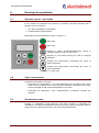
8.1
Operator’s panel - description
In this chapter are examined the functions of operator’s panel and operation with it.
Operator’s panel consists of:
four digit LSD display for visualization;
keyboard with functional buttons;
Description of functional buttons is shown on Figure 8.1.
Motor start
Motor stop
Entering in regime visualization/adjustment, saving of
changed parameter, return in main menu
Rejection or quit without saving the value of changed
parameter
Scrolling the menu/change (increasing) the value of
chosen parameter
Scrolling the menu/change (decreasing) the value of
chosen parameter
Figure 8.1. Panel view
8.2
Types of parameters
Parameters are divided in two types:
Parameters for visualization “b”. By these parameters can be featured the current
value of some constant. When on the terminal is featured a parameter of this kind,
buttons-arrows(▲ and ▼) and DATA/ENTER are not active.
Parameters for adjustment “Х.ХХ”. Characteristics of frequency inverters are
adjusted.
8.3
Visualisation mode
Entering in visualization mode becomes, that after choosing of parameter for
visualization, the button DATA/ENTER is pushed. Secondary press of the button leads to
escape from this mode and returning in the main tree with parameters.
Manual ELDI / V (Revision NEW)
37/73
IUM ELDI/V ENG V1.00 0515
Copyright ELECTROINVENT
8.4
Adjustment mode
Entering in adjustment mode/change of parameter, becomes after reaching the desired
parameter, press the button DATA/ENTER. Its value can be changed with buttons-arrows
(▲ and ▼). To remember the new value it is enough to press DATA/ENTER, after which
we will return again in the main tree with parameters. To refuse or quit without
memorizing the parameter value becomes by pressing ESC.
ATTENTION
Memorizing of parameter becomes after pressing the key DATA/ENTER!
Adjustment of some parameter can be done by the following sequence of actions:
Finding the desired parameter in the menu of parameters, by the use of buttonsarrows▲ and ▼.
Entering in mode correction of parameter by button DATA/ENTER.
Change the value of the parameter by button ▲ and ▼.
Memorizing the parameter by pressing of button DATA/ENTER.
Returning to main menu with parameters without memorizing the change of
parameter, by button ESC.
8.5
Correction mode of parameter type „control word”
Entering in correction mode of parameter type “control word” becomes by button
DATA/ENTER. On the display appears the control word.
Choosing the digit, which has to be changed, becomes by the button arrow-up ▲. By
each pressing of this button it is chosen the next digit to the left. The chosen digit is
blinking.
To change the value of blinking digit becomes by the button arrow-down ▼. By each
pressing of this button, the blinking digit changes its value (“0” or “1”).
The changed control word can be entered by button DATA/ENTER or we can quit
from the change with button ESC.
Manual ELDI / V (Revision NEW)
38/73
IUM ELDI/V ENG V1.00 0515
Copyright ELECTROINVENT
8.6
Examples of operating with keyboard
Figure 8.2. Example 1 - Adjustment the time for acceleration
Figure 8.3. Example 2 - Visualization the running output frequency
ATTENTION
When you change the values of parameters during operation of the motor, it must be
sure, that this change will not bring to emergency. It is recommended the changes of
parameters to be made by stopped motor only.
Manual ELDI / V (Revision NEW)
39/73
IUM ELDI/V ENG V1.00 0515
Copyright ELECTROINVENT
9
Parameters of frequency inverter (version V8)
The parameters of frequency inverter are grouped in 15 functional menus, described
below.
Note: The tables with parameters and values by default are referred to drives 5,5kW and
software version V8. If your software version is different, ask the producer –
“Electroinvent” Ltd or distributor about more actual version of this Manual or Appendix –
table with parameters for your version.
Table 9.1. Used abbreviations
Used abbreviations:
АС motor
asynchronous motor
FB
feedback
PI
proportional- integral
VC
Vector Control
U/f
control mode U/f
P - part
proportional part
I - part
integral part
D/A
digital / analog inputs
PLC
programmable logic controller
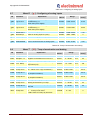
Table 9.2. Speed reference
Menu 0
9.1
№
A.00
A.01
A.02
A.03
A.04
A.05
A.06
A.07
A.08
Parameter
Ref-Int Hz
Ref-Frc Hz
Spd.Ref1 Hz
Spd.Ref2 Hz
Spd.Ref3 Hz
Spd.Ref4 Hz
Spd.Ref5 Hz
Spd.Ref6 Hz
Spd.Ref7 Hz
( A ) - Speed reference
Explanation
Speed reference – full part
Frequency reference – fraction part
Programmable frequency 1 (Ref1)
Programmable frequency 2 (Ref2)
Programmable frequency 3 (Ref3)
Programmable frequency 4 (Ref4)
Programmable frequency 5 (Ref5)
Programmable frequency 6 (Ref6)
Programmable frequency 7 (Ref7)
Manual ELDI / V (Revision NEW)
40/73
MODBUS
address
0x0000
0x0001
0x0002
0x0003
0x0004
0x0005
0x0006
0x0007
0x0008
Range
0 – 400
0.00 – 0.99
0.0 – 400.0
0.0 – 400.0
0.0 – 400.0
0.0 – 400.0
0.0 – 400.0
0.0 – 400.0
0.0 – 400.0
Hz
Hz
Hz
Hz
Hz
Hz
Hz
Hz
Hz
Factory
setting
0
0.00
0.00
0.00
0.00
0.00
0.00
0.00
0.00
IUM ELDI/V ENG V1.00 0515
Copyright ELECTROINVENT
Table 9.3. Visualization
Menu 1
9.2
№
( b ) - Visualization
Parameter
MODBUS
Explanation
b.00
Disp.Par.ID
b.01
Displ.Value
Range
address
Choice of constant for visualization:
0 : Voltage on capacitor battery
1 : Phase current of the motor
2 : Speed of rotation of the motor
3 : Output frequency of inverter
4 : Condition of the drive
5 : Version of the software
6 : Position encoder (инкрементален)
7 : Position encoder (UVW)
8 : State of multifunctional inputs
9 : Reference for pressure (option for pump control)
10 : Pressure FB (by pump control)
Running value of chosen constant
0x0101
0-7
0x0102
-
Factory
setting
V
A
rpm
Hz
atm
atm
-
0
-
Table 9.4. Parameters of the motor
Menu 2
9.3
№
Parameter
( C ) - Parameters of the motor
Explanation
MODBUS
address
Factory
setting
Range
C.00
Unom
V
Nominal line voltage
0x0200
100 - 420
V
380
C.01
Inom
A
Nominal phase current
0x0201
0.5 – 255.0
A
12.0
C.02
Pole pairs
Maximal frequency
0x0202
1 - 10
2
C.03
Enc. Type
Base frequency
0x0203
0–7
0
C.04
Еnc. Pulses
Nominal speed
0x0204
64 - 8000
4096
C.05
Frq Max
Hz
Number of pole pairs
0x0205
25 - 400
Hz
100
C.06
Frq Base
Hz
Type of encoder
0x0206
25 - 400
Hz
50
C.07
Spd nom rpm
Pulses per revolution (digits) of encoder
0x0207
100 - 6000
rpm
1400
C.08
MotPower kW
Nominal power (if assign power 0 kW,
then the entered C.01:Inom is
determining)
0x0208
0.0 - 132.0
kW
0.5
C.09
T_rotor
Electrical time constant of the rotor (only
for AC motors with vector control +
feedback
0x0209
7 - 327
ms
75
ms
Manual ELDI / V (Revision NEW)
41/73
IUM ELDI/V ENG V1.00 0515
Copyright ELECTROINVENT
Table 9.5. General adjustments
Меню 3 ( d ) - General adjustments
9.4
№
Parameter
Explanation
address
d.00
d.01
MainsVtg V
fInvert.kHz
0x0300
0x0301
127 - 440
1 - 14
V
kHz
d.02
MotCtrl Typ
0x0302
0-5
-
0
d.03
Operat.Mode
0x0303
0-5
-
0
d.04
Fan-On Levl
Reference of grid voltage
Reference of carrier frequency
Control mode:
0 – U/f mode for АС motor without feedback
1 – U/f mode for АС motor with feedback
2* –VC mode for АС motor without feedback
3 – VC mode for АС motor with feedback
4*– VC mode for synchronous motor with
permanent magnets without speed feedback
5 - VC mode for synchronous motor with
permanent magnets with speed feedback
*Note: Control modes 2 and 4 (VC without
speed feedback) are not yet activated. By
their selection it must be performed the
corresponding modes with speed feedback – 3
or 5.
Operating mode of the inverter:
0 – Control via reference for Speed
1* – Reserved for future use
2 – Control vie reference for Position
3* – Reserved for future use
4* – Reserved for future use
5* – Reserved for future use
Note: In selection mode, marked as
"Reserved for future use" is implemented by
control via reference for Speed (0)
Fan switch-on level
Activated protections – command word
Factory
setting
380
10
0x0304
0.37–1.00
-
0.7
0x0305
0-3
-
0
0x0306
0-7
-
0
0x0307
0-3
-
0
d.05
d.06
d.07
Prot.Enable
GenCmd.Wrd
Defaults/
Save
bit 3
Reserved
-
bit 2
Reserved
-
bit 1
0-switch-off
1-switch-on
MODBUS
bit 0
0-switch-off
1-switch-on
bit 1 – Activating protection against break-off
of output phase in regime „DC-brake“.
bit 0 – Activating protection against break-off
of output phase during rotation.
Common word for common adjustments
bit 3
bit 2
bit 1
Reserved
(unused)
Type of
analog
speed
reference
Order of
UVW signals
from
encoder
bit 0
Order of
increm.
signals
from
encoder
0-
0–
unsigned
0 – normal
0– normal
1–
1 – signed
1 – reversed
1–
reversed
1: Loading the parameter values of the
recorded backup configuration in RAM of the
inverter
2: Save the current values of the parameters of
RAM as a backup configuration in flash
memory
3: Save the current values of parameters RAM
in the flash memory
4: Reset offset of the absolute encoder saved
Manual ELDI / V (Revision NEW)
42/73
Range
IUM ELDI/V ENG V1.00 0515
Copyright ELECTROINVENT
d.08
9.4.1
Hi-Lvl Appl
in flash memory (when managing synchronous
motor)
Notes:
1. Recording the values of changed
parameters from RAM in the flash
memory is done automatically when
turning off the power. Set the value 3 of
parameter d.07 instantaneously initiates
recording the changed parameters in the
flash memory. These parameters are
automatically loaded from flash memory
to RAM when powering the inverter. The
parameters recorded as a backup
configuration is not automatically loaded
into RAM. They do not change when you
turn off the power, but only when you set
value 2 of parameter d.07.
2. Operations 1-4 are activated only when
inactive (off) status of the inverter
(inactive input "Run").
Selection of specialized program for control:
0 – standard drive
1 – pump control
0x0308
0-1
-
General adjustments - detailed description
Parameter d.00 - Reference of input grid supply
- For supply grid 220V/AC +/-10% - it is entered d.00= 220
- For supply grid 380-420V/AC +/-10% - it is entered d.00= 380-420
Note: Reference the value of parameter becomes by stoped motor. The correct
reference is important for correct operation of protections USF and OSF
Parameter d.01 - Reference of carrier frequency
The carrier frequency is the frequency of PWM, at which works the power unit – the
outputs U,V and W. The choice of carrier frequency depends on:
The distance between the inverter and the motor:
Cable length
Carrier frequency
Table 9.6. Recommended values depending on the cables’ length
up to 50 m
up to 100 m
above 100 m
8 - 12 kHz
4 - 8 kHz
2 – 4 kHz
Depending on the motor power:
Motor power
Carrier frequency
Table 9.7. Recommended values depending on the motor power
from 37 – 100
up to 3kW
from 5 – 15 kW
from 18 – 30 kW
kW
from 11 – 16 kHz from 8 – 11 kHz
from 4 – 8 kHz
from 1 – 4kHz
Note: The change of cerrier frequency obligatory must be done by stoped motor (non
active input CN2-4 On/Off).
Influence of cerrier frequency upon overloading possibilities of the inverter.
When using cerrier frequencies higher than 10kHz, it must be known, that the overloading
possibilities of the inverter decrease and can become lower than 120%. On Figure 9.1 it
is shown the overloading depending on cerrier frequency.
Manual ELDI / V (Revision NEW)
43/73
IUM ELDI/V ENG V1.00 0515
0
Copyright ELECTROINVENT
Figure 9.1. Overload depending on the carrier frequency
Recommendations:
- If at low speed of motor rotation the motor torque is unstable – decrease the carrier
frequency;
- If electromagnetic disturbances from power unit influence to other equipment, near
inverter, decrease the carrier frequency;
- If the leakage current between the inverter’s corpus and protective grounding is
bigger – decrease the carrier frequency;
- If in the motor is heard “metallic” noise – increase the carrier frequency;
Parameter d.02 - Choice of control mode
Control of asynchronous motor with constant ratio U/f without speed feedback
(U/F)
When choosing a d.02 = 0
With this control mode the minimal frequency of rotation, by which the nominal motor
torque is achieved is 2,5 to 5 Hz or 150 to 300 RPM for four-pole motor (1500/50Hz).
The range of regulation by constant torque 1:20 (at Fmax. = 50Hz). Achieving bigger
diapason is for motor torque account. On Figure 9.2. is shown the motor torque in
function of the revolutions.
1,5,0Mдв
Мдв.ном
0,5Мдв.ном
Fnom. 59/60Hz
Fмах 100/120Hz
Figure 9.2.The motor torque in function of the revolutions (U/F)
This control mode doesn’t require parameterization (autotuning) and it is suitable when it
is necessary one inverter to control several smaller motors, connected in parallel to
outputs U, V, W.
It is recommended to be used control of mechanisms, which don’t need high starting
torque and dynamics of motor control.
The mechanisms, for which is recommended to use U/F control mode are: pumps, fans,
conveyo belts, high speed spindles (12000 – 18000 об/мин.), etc.
Manual ELDI / V (Revision NEW)
44/73
IUM ELDI/V ENG V1.00 0515
Copyright ELECTROINVENT
Control of asynchronous motor with constant proportion U/f with speed feedback
When choosing a d.02 = 1 (U/F+OB)
With this control mode can be achieved a nominal motor torque by frequency reference =
0Hz (stopped motor). The range of speed control by constant torque achieves 1:500 (by
Fmax=50Hz). Bigger range can be reached with more precise adjustment of speed
regulator. On Figure 9.3. is shown the motor torque depending on the revolutions.
2,0Mдв
1,5Мдв.ном
Мдв.ном
0,5Мдв.ном
0Hz
Fnom. 59/60Hz
0,5 -3Hz
Figure 9.3. The motor torque depending on the revolutions (U/F + OB)
This control mode doesn’t require parameterization (autotuning). It is necessary to be
entered the parameters of the motor, which are written on the factory’s label. The
parameters, which are especially important for normal work of the motor, are С.04. (
nominal revolutions ) and С.05.(number of pole pairs). On the motor it is mounted sensor
for speed feedback (pulse coder).
The control mode U/F with FB can be applied in cases, when the pulse coder has to be
mounted on the mechanism.
Note:
When pulse coder is mounted on mechanism, it is necessary to be known in advance the
transmission ration between motor and the driven object. In parameter C.07 is interred
the recalculated value of pulses number.
The availability of windage between motor and the pulse coder can cause unwanted
vibrations, which are dangerous for the mechanism and in some cases it can be
damaged.
Recommendation:
- When the pulse coder is mounted on the mechanism, us one with a big number of
pulses.
- When it is needed a large range of speed control, use pulse coder with bigger
number of pulses.
Vector control of asynchronous motor without speed feedback (sensorless)
When choosing a d.02 = 2 - (VC)
With this control mode is achieved stability of motor revolutions in the range of loading
from 0 to +/-2,0 Мmot nom without need of speed feedback. The minimal frequency of
rotation, by which can be achieved 1.5 to 2,0 Мmot.nom is 1,5 to 3 Hz. The motor torque
as function of the revolutions is given on Figure 9.4.
Manual ELDI / V (Revision NEW)
45/73
IUM ELDI/V ENG V1.00 0515
Copyright ELECTROINVENT
2,0Mдв
Мдв.ном
0,5Мдв.ном
Fмах 100/120Hz
Fnom. 59/60Hz
2,5Hz
0H
z
1,5Hz
Figure 9.4. The motor torque as function of the revolutions (VC)
This control mode requires parameterization (autotuning), as follows:
- Full autotuning – when the motor is unknown – there is no factory label. It is
necessary the motor to be disconnected from the driven mechanism;
- Partial autotuning – when the motor is known it is enough to start the function
“Measurement of stator resistance”;
Vector control of asynchronous motor with speed feedback
When choosing a d.02 = 3 - (VC+OV)
With this control mode can be reached double motor torque be frequency reference =
0Hz (stopped motor) (Figure 9.5.). The range of speed regulation by constant torque
reaches 1:1000.
On Figure 9.5. is shown the motor torque as function of motor revolutions.
2,0Mдв
Мдв.ном
0,5Мдв.ном
Fмах 100/120Hz
Fnom. 59/60Hz
0 Hz
Figure 9.5. The motor torque as function of motor revolutions (VC+OV)
This control mode requires parameterization (autotuning) when the motor is unknown –
there is no factory label.
Obligatory condition is on the motor to be assembled a sensor for speed feedback
(encoder) with 1024 to 8000 PPR.
It is recommended to be used for control of mechanisms which require high start torque,
high dynamics and large range of motor speed regulation. It can be used for positioning
and creating of synchronous shaft.
The mechanisms for which this mode can be applied are servo drives and spindle drives
for machine tools, trans manipulators, lifts, etc.
It can realize operation of asynchronous motor as step motor, by control mode type “Step
and direction”. It is suitable for single axes positioning mechanisms, which require high
dynamics, precise positioning and simple control.
Note: This control mode is not recommended to be applied in cases when encoder is
mounted on the mechanism
Manual ELDI / V (Revision NEW)
46/73
IUM ELDI/V ENG V1.00 0515
Copyright ELECTROINVENT
Vector control of asynchronous motor without speed feedback
When choosing a.02 = 4
Note: Control mode № 4 is not realized.
Vector control of asynchronous motor with speed feedback
When choosing a d.02 = 5
This control mode uses high torque motors with permanent magnets. It can be reached
2.0 to 3.0 Mmot by short time torque overloading.
The range of speed regulation is 1:5000. Bigger range can be achieved by precise
adjustment of speed regulator (See Chapter 9.10 Speed regulator). It is not required
parameterization (autotuning).
Obligatory must be entered:
Motor parameters: nominal current, nominal revolutions, number of pole pairs.
Pulse coder parameters: type of pulse coder (C.06); number of pulses per revolution
(C.07)
Note: Pulse coder, mounted to the motor, must have positioning pulse sequence U, U/, V,
V/, W, W/, which has to corresponds to the number of pole pairs of the motor.
Possibilities of the control mode:
It is used for control of mechanisms, which require higher dynamics and large range of
regulation of motor revolutions.
Positioning and creating synchronous shaft between two mechanisms. It can realize
operation of asynchronous motor as step motor, by control mode “Step and direction”.
The mechanisms, for which it is applicable, are: servo drives for machine tools, trans
manipulators, aggregate machines, lifts, etc, which use synchronous motors with
permanent magnets.
Parameter d.03 – Operating mode of the inverter
The speed control of the inverter is carried out by any of the three main modes:
-
Control via reference for speed, at which the assignment submitted by a digital /
analog multifunctional input via serial (MODBUS) interface or the command panel,
directly determines the speed of the motor. This mode is selected when the
parameter d.03 is set value 0 (d.03 = 0).
-
Control via reference for position in which the assignment submitted by the special
fast digital multifunction inputs or through the serial (MODBUS) interface defines the
desired position of the motor shaft. The angular velocity, with which reaches the
specified position depends on the pulse frequency entering in the fast digital inputs
or (when managing via serial interface) from the interval and pitch renovation of
reference for position. In control mode by position are relevant also selected settings
of the positional regulator - parameters J.05, J.06, J.07. This mode is selected
when the parameter d.03 is set value 2 (d.03 = 2).
-
Control via reference for torque. This operation is not implemented in this version of
the inverter.
-
Besides the above three main modes of operation are possible theirs variations
which will be described after they are implemented. In the present implementation of
the inverter are preserved values of d.03, with which to set the unrealized currently
operating modes. For greater distinctness, at embezzlement of d.03 any of the
values marked "reserved" in practice has realized mode 0 (speed control).
Manual ELDI / V (Revision NEW)
47/73
IUM ELDI/V ENG V1.00 0515
Copyright ELECTROINVENT
Parameter d.04 - Threshold of fan switch-on
The fan (if such is available in the article) is switching on when the temperature is
increased above the threshold of actuation and then switching off when it falls below the
specified in d.04. When increasing the value of d.04 the temperature threshold of
switching on the fan is decreased. If d.04 is set to maximum value (1.00), the fan will be
permanently switched on.
Adjustment range: 50-130 ̊С (60 ̊С)
Parameter d.05 - Activating of protections
Activating of protections command word
bit 3
bit 2
Reserved
Reserved
bit 1
bit 0
0 - switched off
0 - switched off
1- switched on
1- switched on
Protection against interruption of output phase during rotation – bit 1
By setting of bit 0=1 it is activated protection against interruption of output phase during
rotation. By setting of bit 0 = 0 the protection is switched-off.
This protection protects the motor from damage in cases, when:
The output frequency is higher than the basic – above 50/60Hz and the chosen duty
mode is U/f. In this case the current, flowing between two other phases is not
enough to activate the protection from overloading of inverter.
There is a circuit closer on the output circuit.
This can happen in lift mechanisms, where between the inverter and the motor there is
obligatory contactor, from security point of view.
ATTENTION
The protection must be switched-on, when the inverter is used to control lift. The
damage of contactor lamellas during lift movement can cause serious trouble!
Protection against interruption of output phase in “DC-brake” mode – bit 0
By setting of bit 1 = 1 it is activated protection against interruption of output phase in
“DC-brake” mode;
By setting of bit 1 = 0 the protection is switched-off;
This protection is recommended to be used, when there is contactor in the output circuit
between inverter and motor and it is used in stop regime DC-brake. By switch-off of
contactor, connected in the output circuit, during the work of DC brake, it is created
electrical arc, which can set it in fire and cause serious damages.
ATTENTION
The protection must be switched-on, when the inverter is used to control lift with
switched-on regime for stop DC-brake.
Manual ELDI / V (Revision NEW)
48/73
IUM ELDI/V ENG V1.00 0515
Copyright ELECTROINVENT
Parameter d.06
Configuring of common parameters becomes by the four bits of control word.
bit 3
Reserved for future
use (unused)
bit 2
Type of analog
speed reference
bit 1
Sequence of UVWsignals
Table 9.8. Control word
bit 0
Sequence of signals from
the incremental encoder
Description of control word:
bit 3 - Reserved for future use (unused)
bit 2 - Chosing a type of analog speed reference
If the differential analog input is set to function "Speed reference" (analog input
function 65), then by bit 2 is chosen whether this analog reference is unipolar or
bipolar. When inserting bit 2 = 0 assignment is unipolar (number without sign
regardless of the polarity of the signal), if it is necessary configure additional
digital input to set the direction of rotation. When inserting the bit 2 = 1
assignment is bipolar, the direction of rotation is determined by the polarity (sign)
of the input signal.
bit 1 - Sequence of UVW-signals from encoder (if available)
Bit 1 is used to manage the synchronous motor with the help of encoder with
UVW - outputs. In case that it is necessary to change the sequence of UVWsignals, this can be performed either by physical connection (crossing), and by
inverting the bit 1.
bit 0 - Sequence of signals from the incremental encoder (if available)
In case that it is necessary to change the order of the outputs (A, B) of the
incremental encoder to ensure the phasing of the speed feedback, this can be
performed either by physical connection (crossing), and by inverting the bit 0.
ATTENTION
When you change the polarity of the feedback is necessary for the motor to be
uncoupled from the mechanism which drives. It must be ensured that this will not lead
to an accident. It is recommended to change it when the engine stopped.
The management of the inverter can be done both through multifunction digital and / or
analog inputs, and through serial (MODBUS) interface. Version of control through serial
interface and control through the control panel, which is also connected to the inverter via
the serial port.
The general principle is that if a function (command) is configured on a multifunctional
input, the same function / command can not be fed through the serial interface or the
command panel. Conversely, if a function (command) is not associated with any of the
multifunction inputs, it can be submitted via the serial interface or the command panel.
Example:
- Let digital function "Start / Stop" (function 2) is configured to multifunctional Input # 3.
Then the drive is starting / stopping vie Input # 3. If the commands “Start / Stop”, be
submitted via the serial interface or the command console, they are ignored.
- if digital function “Start / Stop”( function 2) is not configured to any of the
multifunction inputs, then the the drive is starting / stopping of the serial interface or
via the command console.
The options for control (the commands "Start / Stop" and "Direction") by multifunctional
inputs via control terminal are:
Two-wire scheme for “Start” and “Stop” of inverter.
The factory setting mode implements a 2-wire scheme. At input CN2-4 and CN2-12 are
assigned functions 2 (ON) and 3 (F / R).
Manual ELDI / V (Revision NEW)
49/73
IUM ELDI/V ENG V1.00 0515
Copyright ELECTROINVENT
After turning on the input CN2-4 the inverter starts with the direction of rotation Fwd. After
disconnecting the input, the inverter stops controllable or momentum depending on the
choice.
Figure 9.6. Two-wire scheme for “Start” and “Stop” of inverter
After turning on the input CN2-4 and activate the input CN2-12 is executed command
reverse (Rev). - the inverter stops controllable and reverses the rotation of the motor
(Rev). The wiring diagram is shown in Figure 9.6.
During the assignment at input CN2-4 and CN2-12 functions 4 (Run Left)) and 5 (Run
Right), the starting and stopping is in the following sequence:
After turning on the input CN2-4 the inverter starts with the direction of rotation Fwd. After
disconnecting the input, the inverter stops controllable or momentum depending on the
choice.
Three-wire scheme for “Start” and “Stop” of inverter.
At inputs CN2-4, CN2-12 and CN2-13 are assigned functions 4 (Run Left), 5 (Run Right)
and 1 (run). Starting and stopping is in the following sequence.
To turning on the inverter must be enabled input CN2-13 which is assigned to the function
1 (run).
After turning on the input CN2-4 the inverter starts with direction of rotation Fwd. The
exclusion is when you switching off the input CN2-13.
After turning on the input CN2-12 the inverter starts with direction of rotation Rev. The
exclusion is when you switching off the input CN2-13. On Figure 9.7. is shown the wiring
diagram.
Figure 9.7. Three-wire scheme for “Start” and “Stop” of inverter
Manual ELDI / V (Revision NEW)
50/73
IUM ELDI/V ENG V1.00 0515
Copyright ELECTROINVENT
Parameter d.07 - Recording / restoring the values of configuration parameters
The parameter d.07 serves mainly to record the complete configuration in the permanent
(flash) memory of the inverter, as well as to restore the saved configurations.
When the inverter is powered up, the configuration parameters which determine the
behavior of the drive are in energy-dependent operative memory (RAM).
After turning off the power supply, all parameters of the current configuration is
automatically saved in non-volatile memory (FLASH).
When the power supply is turned on, all parameters of non-volatile memory (FLASH) are
copied into operational memory. This restores the configuration of the inverter before the
last power-off. This is called "automatic configuration", which is recording and restoring
automatically without external command.
When changing some configuration parameters may lead to undesired behavior of the
drive compared to condition before the start of the changes. In case that there are many
changes, the recovery "by memory" on the last working configuration may be impossible.
To provide a way out of this difficult situation, there is an opportunity to record the
"backup configuration“. This configuration is stored in a separate area of flash memory
so that it does not change the automatic recording of the current configuration after
turning off the power supply.
It is recommended after changing configuration parameters and achieving well
functioning configuration, this configuration to be saved as a "reserve“. This is done when
d.07 is set value 2: d.07 = 2 (after saving the configuration, the value of d.07
automatically returns 0). So the recorded backup configuration remains unchanged until it
is overwritten as described above. Copying the backup configuration of flash memory in
operational memory becomes as d.07 is set value 1: d.07 = 1.
The current configuration can also be saved to flash memory not only automatically
(when turning off the power supply), but forced - as at d.07 is set value 3: d.07 = 3.
Besides described three main functions of d.07, this parameter can be used to reset the
records in flash memory offset of the absolute encoder (if available) to the rotor of the
motor.
This may be necessary when replacing the motor or encoder using a synchronous motor.
The reset of the offset force the execution of the operation "orientation of the rotor" in next
command "Start" followed by recording the new offset in flash memory. The reset of the
offset became as d.07 is set value 4: d.07 = 4.
Note: Each of the described operations can be activated only in inactive state of the
inverter - after power on the power supply or after command "Stop”.
Parameter d.08 - Selection of specialized program
There are selected specialized programs, developed for concrete applications.
Each specialized program realizes automated control of the drive by defined algorithm, by
which can be avoided the necessity for use of external system for automated control of
corresponding technological process.
This parameter has to possible values:
0: Ordinary universal drive;
1: Specialized system for automated control of pumps;
Manual ELDI / V (Revision NEW)
51/73
IUM ELDI/V ENG V1.00 0515
Copyright ELECTROINVENT
Table 9.9. Multifunctional inputs
Menu 4
9.5
№
Parameter
( Е ) - Multifunctional inputs
Explanation
MODBUS
address
Factory
setting
Range
Е.00
Inp1 func
Multifunctional Digital/Analog input 0
(-AI1 /CN2-6, +AI1/CN2-7)
0x0400
0 - 172
-
0
Е.01
Inp2 func
Multifunctional Digital/Analog input 1
(AI2U /CN2-9)
0x0401
0 - 172
-
0
Е.02
Inp3 func
Multifunctional digital input 2 (ON/CN2-4)
0x0402
0 - 120
-
2
Е.03
Inp4 func
Multifunctional digital input 3 (F/R/CN2-12)
0x0403
0 - 120
-
3
Е.04
Inp5 func
Multifunctional digital input 4 (DI1/CN2-13)
0x0404
0 - 120
-
12
Е.05
Inp6 func
Multifunctional digital input 5 (DI2/CN2-14)
0x0405
0 - 120
-
13
Е.06
Inp7 func
Multifunctional digital input 6 (DI3/CN2-10)
0x0406
0 - 120
-
14
Е.07
Dg.Pot.Step+
Digital potentiometer – step for increasing
0x0407
0,0 - 31,9
Hz
1.0
Е.08
Dg.Pot.Step-
Digital potentiometer – step for decreasing
0x0408
0,0 - 31,9
Hz
1.0
Е.09
DgPotRamp+
Digital potentiometer – speed for increasing
0x0409
0,0 - 31,9
Hz/
sec
0.0
Е.10
Dg.PotRamp
Digital potentiometer – speed for decreasing
0x040A
0,0 - 31,9
Hz/
sec
0.0
Е.11
PI-Reg kP
External PI-regulator Proportional coefficient of amplifying (P)
0x040B
0 - 9999
-
0
Е.12
PI-Reg kI
External PI-regulator Integral coefficient of amplifying (I)
0x040C
0 - 9999
-
0
Е.13
I/O-CmdWrd
Control word for multifunctional Inputs
bit3
bit 2
bit 1
bit 0
Reserv Reserv Reserv
external PI
.
.
.
0 – non active
1 - active
Note:
By activation of external PI-regulator, on some
of analog inputs obligatory is assigned
function 72 (FB for external PI-regulator).
0x040D
0000 0001
-
0
Е.14
FastInpMode
Operating mode of fast digital inputs
0x040E
0-4
-
0
Manual ELDI / V (Revision NEW)
52/73
IUM ELDI/V ENG V1.00 0515
Copyright ELECTROINVENT
Table 9.10. Functions of digital / analog inputs
Functions of digital / analog inputs
Number of
the function
9.5.1
Name of the function
0
Non-congigured (no input function assigned)
1
Emergency Stop
2
Start of inverter (On/Off)
3
Change of rotation direction (Forward/Reverse)
4
Start with rotation direction – left (Run Left)
5
Start with rotation direction – right (Run Right)
6
DC-brake
7
Faults Reset
8
Acceleration/deceleration - stop
9
Reference of Boost 2
10
Start of analog signal (Ana Start/Stop)
11
Programmable output frequency - F1
12
Programmable output frequency - F2
13
Programmable output frequency - F3
14
Electronic potentiometer – increase of frequency
15
Electronic potentiometer – decrease of frequency
16
Programmable current limitation 1
17
Programmable current limitation 2
18
Enable the additional "P" - coefficient of speed regulator
19
Position reference – prohibition/permition
20
Position reference – reset
65
Reference for frequency (speed)
66
Feedback fore speed
67
Reference for limitation of the moment
68
Reference for acceleration (not active)
69
Level of DC-brake
70
Level of current limitation by acceleration
71
Level of current limitation by stop
72
Feedback for external PI-regulator
Type of the
function
Digital
Analog
Polarity of multifunctional inputs
Numbers with which are assigned the functions of multifunctional inputs correspond to
"positive" polarity. This means:
-
for digital input functions – active state in closed contact inactive state in open
contact;
for analog input functions (of differential input) – at positive potential on input "+"
compared to input "-", the input signal is perceived as positive, in the opposite
case - as negative;
In case of necessity, the polarity of the input functions can be inverted without physical
change in the input compounds. This happens as the number, corresponding to an input
function, is increased with displacement equal to 100.
Manual ELDI / V (Revision NEW)
53/73
IUM ELDI/V ENG V1.00 0515
Copyright ELECTROINVENT
For example, if digital input is configured function 2 (Start / Stop), the command "Start"
will be submitted by close contact and "Stop" - through open contact. The inverting of this
logic is implemented as on the same input is assigned function 102 (instead 2). Then the
command "Start" will be fed through an open contact and "Stop" - through closed contact.
The same principle is valid for bipolar analog input functions, such as the replacement of
function 65 (analog speed reference) with 165 leads to a change in the specified direction
of rotation.
9.5.2
Using the fast digital inputs
Two of the multifunction digital inputs are characterized by a high performance and can
accept input signals at a frequency up to 200 kHz. One of the two "fast" inputs is
conventionally accepted as "Main" and the other for "Auxiliary”.
The „Main“ fast input is DI3, изведен е на контролна клема CN2-10. Конфигурирането
на функции на този вход става чрез параметър E.06.
„Спомагателният“ бърз вход е DI1, outputted on the control terminal CN2-13. The
configuration of features of this input is through a parameter E.05.
On fast digital inputs can be configured each of the input digital functions in which these
inputs will behave as normal digital inputs.
The higher performance of fast digital inputs enables them to perform functions
unavailable to other inputs. For the purpose:
-
on parameters E.05 and/or E.06 , whereby are configured functions of fast digital
inputs are assigned a value of 0 (no set input feature);
by parameter E.14 is defined the operating mode of one or both fast digital inputs;
The operating modes of the fast digital inputs are explained in the table below:
Table 9.11. Operating modes of the fast digital inputs
Operating modes of the fast digital inputs
Identifier
Description of the mode
0
The inputs are not used as "fast" inputs
1
Reference for speed with Pulse Width Modulation (PWM) with frequency up to 1.0 kHz. Only
one (Main) fast input is used. The second fast input can work as a simple digital input.
2
Reference for position type „Step + Direction“. The main fast input is fed with pulse sequence
up to 200 kHz, the auxiliary fast input serves to set the direction
3
Reference for position with two square pulse sequences. The fast inputs are fed with pulse
sequences up to 200 kHz in square (phase shifted 90 degrees)
4
Reference for position with separate pulse sequences for both directions of rotation. This
mode of operation of the fast inputs is not enabled.
Note: When at parameter E.14 is configured “set a position”, by parameter d.03 must be
chosen mode of "Control by reference for position“ (d.03 = 2) from general settings.
Manual ELDI / V (Revision NEW)
54/73
IUM ELDI/V ENG V1.00 0515
Copyright ELECTROINVENT
Functions of digital inputs – detailed description
9.5.3
№
0
1
2
3
4
5
6
Name
Not configured
Emergency Stop
Start (On/Off)
Change of
direction of
rotation
Start with
direction of
rotation – left
(Run Left)
Start with
direction of
rotation – right
(Run Right)
DC-brake
Table 9.12. Functions of digital inputs – detailed description
Description
Not assigned input function
This function performs fast stop of the motor and switch-off of inverter by
activating of digital input. The stop tempo is specified in H.02
Note: When necessary the fast stop, it must be mouinted a suitable brake resistor
on the output terminals of the inverter
The function provides start of the inverter.
Note: At simultaneously set of the mutually exclusive pairs functions
2/3(Start/Stop+Direction) and 4/5(Start with the left direction/ Start with the right
direction), is perceived the second type of control - Start with the left direction/
Start with the right direction)
The function secures the change of direction of rotation of the motor.
See above the note to fuction 2.
The function secures the start of inverter and rotation of the motor in direction –
left.
See above the note to fuction 2.
The function secures the start of inverter and rotation of the motor in direction –
right.
See above the note to fuction 2.
By activating the input, announced for DC-brake of the motor, it is supplied DC
voltage or DC currect depending of the choice in q.06 – bit 3.
- By choice q.06 – bit 3=0 it is supplied output voltage in percents from nominal
motor voltage
- By choice q.06 – bit 3=1 it is supplied output current in percent from nominal
current
The values of output DC voltage or current are specified depending of the choice
in q.06 – bit 2
- By choice q.06 – bit 2 =0 the value of output DC voltage or current is specified in
parameter q.06 = ХХ
- By choice q.06 – bit 2 =1 1 the value of output DC voltage or current is specified
in parameter from analog voltage supplied of one of two analog inputs, which is
announced as input for brake control (E.00=69, or E.01=69). The scale is
specified in parameter q.00, and range of reference regulation – from parameters
on analog input - g.02 or g.05
The exit from regime DC-brake becomes by:
- Switch
- Activating of digital input, announced for specifying the output frequency.
From analog input, announced to specify the output frequency. The initial
frequency, form which it starts, is specified from the threshold for activating the
analog input with parameter n.03
By switch-off of digital input the entering in regime DC-brake becomes by:
- Arriving the output frequency, specified in parameter q.03 (by n.01= 0)
- Immediately, when parameter n.01 = 1
After expiry of time, , specified in n.06, when parameter n.01 =2
The functioning of DC-brake by Fref reference from digital inpit with activated
time for - ton and - toff is shown on Figure 9.8.
Manual ELDI / V (Revision NEW)
55/73
IUM ELDI/V ENG V1.00 0515
Copyright ELECTROINVENT
run
F ref
DC-спирачка
Fout
DCC
ACC
О,03
О,02
О.00
Figure 9.8
7
Protection reset
Note: The function is not active.
By activating of digital input it is stoped the increase, respectively – it is stoped the
decrease of the output frequency during acceleration and stop of the motor
(Figure 9.9.) By switch-off on the input, the process of acceleration and stop of the
motor continues.
run
ACC/DCC-stop
8
ACC/DCC- stop
Fout
ACC
DCC
ACC/DCC-stop
Figure 9.9.
9
Reference for
Boost2
Note: The function is not active.
10
Start from analog
signal
(Ana Start/Stop)
Note: The function is not active.
By activating of 3 digital inputs, choosen to specify the frequency, can be specified
in total 7 different frequencies, depending on the combinations of switching. The
fixed frequencies are entered with parameters from A.02 to A.08.
Table: Choice of fixed frequency
11
12
13
Programmable
frequency - F1
Programmable
frequency - F2
Programmable
frequency - F3
Manual ELDI / V (Revision NEW)
Parameter
Symbol
A.02
Programmable frequency (Ref1)
A.03
Programmable frequency (Ref2)
A.04
Programmable frequency (Ref3)
A.05
Programmable frequency (Ref4)
A.06
Programmable frequency (Ref5)
A.07
Programmable frequency (Ref6)
A.08
Programmable frequency (Ref7)
оn – activated input
56/73
F3
F2
F1
on
on
on
on
on
on
on
on
on
on
on
on
IUM ELDI/V ENG V1.00 0515
Copyright ELECTROINVENT
14
15
16
17
Electronic
potentiometer –
Increase of the
frequency
Electronic
potentiometer –
Decrease of the
frequency
Programmable
current limitation
– L2, L1
Note: At simultaneously configured digital (with functions 11, 12, 13) and analog
reference source for frequency (speed), is implemented digital reference if at least
one of these digital inputs is submitted active level (‘on’). The analog reference is
executed when all digital sources of reference were in an inactive ('off') state.
This function ensures step increase of output frequency by activating of digital
input
The step for increase of the reference is specified in parameter Е.07.
The speed of increase of the reference is specified in parameter Е.09
Secures step decrease of output frequency by stop of the inverter.
The step of decreasing of the reference is specified in Е.08.
The speed of decrease of the reference is specified in parameter Е.10.
By activating one or two digital inputs, choosen as inputs for specifying the current
limitation, can be specified in total 3 different levels. The fixed values are entered
in parameters from I.03 to I.05 as percent from maximal current limitation.
Table: Choice of fixed current limitations
Parameter
Symbol
I.03
Programmable current limitation Ref1
I.04
Programmable current limitation Ref2
I.05
Programmable current limitation Ref3
оn – activated input
L2
L1
on
on
on
on
18
Enable the
additional "P" coefficient of
speed regulator
At active level at the input, on which is configured digital input function 18, the
main „P“- coefficient (J.00) of PID-speed regulator is replaced by the Additional
„P“- coefficient (J.01).
19
Prohibition /
permition of the
position reference
This function forbids receiving of position reference:
By activating of digital input, for which the function is announced, the inverter
doesn’t execute the specified position, locks the entrance of pulses for the
reference, which are supplied on the input of the position regulator.
By switching-off of the input, the inverter can execute the referenced position.
20
Position reference
- reset
By activated digital input, to which the function is announced, the running position
is nulled. By switch-off of the input, the inverter executes the specified
positionagainst the initially specified (null) position.
Manual ELDI / V (Revision NEW)
57/73
IUM ELDI/V ENG V1.00 0515
Copyright ELECTROINVENT
Functions for analog inputs – detailed description
9.5.4
№
Name
Table 9.13. Functions for analog inputs – detailed description
Description
The function is used, when the reference for frequency is supplied on analog
input as voltage or from potentiometer. The reference can be voltage 0 - +10V or
current 0/4-20mA. The parameters on analog input are specified in g.
Note:
1. The function “reference for frequency” can be assigned on one analog input
only. Otherwise an error CFG appears “Wrong configuration“.
2. The reference for frequency can be combined – from digital and from analog
input, as priority have the digital inputs.
3. The reference can be bipolar 0-+/-10V in case it is used a differential in put
AI1. The direction of rotation is defined from the polarity on the input.
4. When a parameter d.06 (from "General Settings") analog speed reference is
configured as bipolar, digital function 3 ("Direction of rotation") is ignored.
65
Reference for
speed (frequency)
by analog input
66
Feedback by speed
by analog input
The function is used when the speed feedback is an analog signal (tachometer)
67
Reference for
torque limitation by
analog input
The function is used, when it is necessary to limit the torque of the motor from
analog input. The reference can be voltage 0 +10V or current 0/4-20mA on the
analog input.
Note: The function is active in a method of control: „Vector control with
feedback”
68
Reference for
acceleration by
analog input
Note: The function is not active.
69
Reference for the
level of DC-brake
by analog input
The function is used, when it is necessary to control the level of DC-brake by
analog input.
Note: To work this function it is necessary to be configured correctly O.ХХ – “
Parameters of DC-brake ”
70
71
72
Reference for the
level of current
limitation during
acceleration by
analog input
Reference about
the level of current
limitation during
stop by analog
input
Feedback for
external PI regulator
The function is used, when it is necessary to limit the level of the current
(respectively the torque) during acceleration of the motor, when the reference is
from analog input.
Note: The function is not active.
The function is used, when it is necessary to limit the current (respectively the
torque) during established speed of the motor, when the reference is from
analog input.
Note: The function is not active.
This function is used when the frequency inverter also serves as a
programmable controller (PLC), receives assignment (temperature, flow,
pressure, etc.) feedback. by relevant sensor and through PI regulator set value
is stabilized by controlling the motor speed.
To activate this input function, it is necessary:
1. In the control word for multifunctional inputs (parameter Е.13) to be
configured external PI-regulator.
2. Function 72 to be assigned on one of multifunctional analog inputs. The
adjustment of parameters of PI-regulator is done with parameters:
I.18 - External PI-regulator – proportional coefficient of amplification (P)
I.19 – External PI-regulator – integral coefficient of amplification (I)
Note: By activation of special program for pump control, (d.08 = 1) it is
automatically configured for use of external PI-regulator.
Manual ELDI / V (Revision NEW)
58/73
IUM ELDI/V ENG V1.00 0515
Copyright ELECTROINVENT
Table 9.14. Multifunctional outputs
Menu 5
9.6
№
Parameter
F.00
F.01
F.02
F.03
F.04
F.05
F.06
F.07
F.08
F.09
IoOut1 Func
IoOut2 Func
IoOut3 Func
IoOut4 Func
Z-Speеd/rpm
ZS-Hyst rpm
SA-Hyst rpm
SA-Zone rpm
Timer Start
Timer Stop
F.10
ZeroSpdMode
F.11
( F ) - Multifunctional outputs
MODBUS
Explanation
address
Function of digital/analog output AO1
Function of digital/analog output AO2
Function of digital output [FL]
Setting function on digital output [RUN]
Zero speed
Hysteresis at zero speed
Hysteresis at arrived speed
Zone of arrived speed
Timer by start
Timer by stop
Operating mode at “Zero speed” and
“Speed Arrival”
0 – from speed feedback
1 – from speed reference
Operating mode of analog outputs
ModeAnaOut
bit 3
bit 2
bit 1
bit 0
-
-
Analog out. 2
Analog out.1
-
-
0 - bipolar
0-bipolar
-
-
1-unipolar
1-unipolar
Factory
setting
Range
0x0A00
0x0501
0x0502
0x0503
0x0504
0x0505
0x0506
0x0507
0x0508
0x0509
0 - 14
0 - 14
0-8
0-8
1 - 120
1 - 60
1 - 60
1 - 60
0-32000
0-32000
Hz
Hz
Hz
Hz
ms
ms
4
8
1
2
30
12
12
12
0
0
0x050A
0-1
-
0
0x050B
0-3
-
0
-
1.000
-
0.000
-
1.000
-
0.000
F.12
GainAnaOut1
Amplification on analog output 1
0x050C
F.13
OfstAnaOut1
Offset on analog output 1
0x050D
F.14
GainAnaOut2
Amplification on analog output 2
0x050E
F.15
OfstAnaOut2
Offset on analog output 2
0x050F
0.0001.000
-0.4000.400
0.0001.000
-0.4000.400
Table 9.15. Functions of digital / analog outputs
Functions of digital / analog outputs
Number of the function
0
1
2
3
4
5
6
7
8
9
10
11
12
13
Number of the function
Non configured (there is no preset function)
Ready
Zero Speed
Speed Arrival
Start-Stop
DC-brake(the brake is activated)
Low current limitation
High current limitation
Timer start-stop
DC-voltage
Phase current
Motor speed
Output frequency of inverter
Output of speed regulator
Manual ELDI / V (Revision NEW)
59/73
Number of the function
Digital
Analog
IUM ELDI/V ENG V1.00 0515
Copyright ELECTROINVENT
9.6.1
Polarity of digital outputs
The numbers with which are assigned functions of multifunctional digital outputs
correspond to "positive" polarity. This means that when activated digital function the
corresponding output contact is closed and reverse - for non-activated digital function, the
starting contact is open.
In case of necessity, the polarity of the output functions can be inverted without physical
modification of the starting compounds. This happens as the number, corresponding to
an input function, is increased with displacement equal to 100.
For example, if a digital output is configured output function 1 ("Ready"), then when the
inverter is able "Ready" the starting contact is closed. Inverting this logic is implemented
as the same output assign function 101 (instead 1). Then the state "Ready" will be
indicated by an open contact and the absence of "Ready" - through closed contact.
Functions of digital outputs – detailed description
9.6.2
№
Name
Table 9.16. Functions of digital outputs - detailed description
Description
The output is not configured
0
Non configured
1
Ready
Digital output is switched-on, when there is protection triggered. The inverter is
ready for operation
2
Zero Speed
Digital output is switched-on, when the reference for output frequency or the
speed feedback signal (depending on the choice of parameter F.10) is bigger
that the referenced in F.04 value
The digital output is switched-on, when the output frequency becomes higher
or smaller than the referenced (respectively the signal for feedback) and it is
switched-off when the output frequency arrives the referenced +/- hysteresis,
preset in F.06 (Figure 9.10)
3
Speed Arrival
Figure 9.10.
4
Start-Stop
The digital output is switched-on, when the output frequency becomes higher
or smaller than the referenced (respectively the signal for feedback) and it is
switched-off when the output frequency arrives the referenced +/- hysteresis,
preset in
5
DC-brake (brake is
activated)
The digital output is switched-on, when the DC-brake is activated (Figure
9.11).
Manual ELDI / V (Revision NEW)
60/73
IUM ELDI/V ENG V1.00 0515
Copyright ELECTROINVENT
Figure 9.11
The digital output is switched-on, when the inverter is in current limitation by
acceleration preset in I.00 and it is switched-off by exiting the current limitation
(Figure 9.12)
d.00
d.02
Low current
limitation
I<d.02
ACC
d.01
6
Fou
I> d.01
I> d.02
d.00
I> d.01
I< d.01
Out ниско токоограничение
Out Високо токоограничение
I> d.02
Figure 9.12
7
High current
limitation
The digital output is switched-on, when the inverter is entered in high current
limitation, specified in I.01 during acceleration or in established regime and it is
switched-off by exting the current limitation.
The digital output is switched-on, after run out of the time preset in F.08 (Timer
Start) by given command for starting the inverter.
The digital output switches-off after run out of the time preset in F.09
(Timer/Stop)
when the output frequency (reference for output frequency) becomes = 0 Hz
run
Fref
Fout
8
Timer Start-Stop
O.04
O.05
L.08
L.09
Tamer/start stop
Figure 9.13
Note: This function is suitable for control of mechanical brake for lifts and
cranes.
Manual ELDI / V (Revision NEW)
61/73
IUM ELDI/V ENG V1.00 0515
Copyright ELECTROINVENT
Functions of analog outputs – detailed description
9.6.3
№
Name
9
DC-voltage
Table 9.17. Functions of analog outputs - detailed description
Description
Analog value is proportional to the voltage of DC bar of the inverter.
The zero of the voltage corresponds to Table 9.18:
Table 9.18.
Output type
0.0mA to 20 mA
4.0mA to 20 mA
Voltage
Unipolar
0,0mA
4,0mA
0,0V
The range - 0mA to 20 mA (4mA to 20 mA) corresponds to 800V/DC
Analog value is proportional to the phase current. Zero of phase current
corresponds to Table 9.19:
Table 9.19.
Output type
10
Phase current
0.0mA to 20 mA 4.0mA to 20 mA
Voltage
Unipolar
0,0mA
4,0mA
0,0V
Bipolar
10mA
12mA
2,50V
The range - 0mA to 20 mA (4mA to 20mA) corresponds to 2. Inom.
11
Motor speed
Analog value is proportional to the real speed of the motor measured from
speed feedback sensor. The zero speed corresponds to values in Table 9.19:
The range - 0mA to 20 mA (4mA to 20 mA) corresponds to the maximal speed.
Note: In case the selected control mode is without speed feedback, the signal is
proportional to the speed reference, but not to the real speed.
12
Output
frequency of
inverter
Analog value is proportional to the frequency at the output terminals of inverter.
The range - 0mA to 20 mA (4mA to 20 mA) corresponds to the maximal speed.
Output of the
speed regulator
Analog value is proportional to the output of the speed regulator. Regulator’s
zero corresponds to Table 9.19:
The range - 0mA to 20 mA (4mA to 20 mA) corresponds to the maximal value on
the output of speed regulator.
Note: The output signal is different from zero, only by configured control mode
with speed feedback.
13
Note: When the analog output is voltage, it it necessary to mount resistor 250Ω between
it and output GND.
The values of parameters F.12 - F.15 are adjusted depending on the choice 0,0 - 20,0mA
4,0 -20mA or voltage output (with assembled resistor 250Ω) They are specified in Table
9.20.
Parameter
Name
Current output
0-20mA
Table 9.20. Scaling the analog outputs
Current output
Voltage output
4.0-20,0mA
0-5,0V
F.12
Amplification output 1
1.000
1.000
1.000
F.13
Offset on output 1
0,000 +/- 0,002
0,200 +/- 0,002
0,000 +/- 0,002
F.14
Amplification output 2
1.000
1.000
1.000
F.15
Offset on output 2
0,000 +/- 0,002
0,200 +/- 0,002
0,000 +/- 0,002
Manual ELDI / V (Revision NEW)
62/73
IUM ELDI/V ENG V1.00 0515
Copyright ELECTROINVENT
Table 9.21. Configuring of analog inputs
Menu 6
9.7
№
Parameter
( g ) - Configuring of analog inputs
MODBUS
Explanation
address
Range
Factory
setting
g.00
LogLevel-Lo
Voltage, under which the signal is
considered log. ‘0’
(when the input is digital)
0x0600
0.050–0.200
-
0.150
g.01
LogLevel-Hi
Voltage, above which the signal is
considered log. ‘1’
(when the input is digital)
0x0601
0.250-0.600
-
0.300
g.02
GainAnaInp1
Gain on analog input AI1
0x0602
0.000–4.000
-
1.00
g.03
OfstAnaInp1
Offset on analog input AI1 (Od1)
0x0603
-9999 +9999
-
0
g.04
GainAnaInp2
Gain on analog input AI2V (Gd2)
0x0604
0.000- 4.000
-
1,00
g.05
OfstAnaInp2
Offset on analog input AI2V (Od2)
0x0605
-9999 +9999
-
0
RefDeadBand
Zone of insensitiveness of analog inputs
0x0606
0.000 –0.200
-
0.00
g.06
Table 9.22. Temp of acceleration and braking
Menu 7
9.8
№
Parameter
( H ) - Temp of acceleration and braking
Explanation
MODBUS
address
Factory
setting
Range
H.00
RampAcc .1s
Positive acceleration from 0 to Fmax
0x0700
0 - 32760
0.1s
50
H.01
RampDcc .1s
Negative acceleration from Fmax to 0
0x0701
0 - 32760
0.1s
50
H.02
RampEmg .1s
Tempo in emergency stop (dccE)
0x0702
0 - 32760
0.1s
50
H.03
I-Lim Ramp
Negative acceleration in regime of high
torque limit (U/f)
0x0703
10 - 1000
0.1s
100
H.04
S-ramp Acc1
S1 – radius of arc 1 (by acceleration)
0x0704
0.000–0.500
-
0.010
H.05
S-ramp Acc2
S2 – radius of arc 2 (by acceleration)
0x0705
0.000–0.500
-
0.010
H.06
S-ramp Dcc1
S3 – radius of arc 3
(by stop/decceleration)
0x0706
0.000–0.500
-
0.010
H.07
S-ramp Dcc2
S4 – radius of arc 4
(by stop/decceleration)
0x0707
0.000–0.500
-
0.010
H.08
S-ramp Ref0
Starting frequency by S-ramp
0x0708
0.000–0.500
-
0.000
S-ramp Acc2
Starting acceleration by S-ramp
0x0709
1 - 32760
0.1s
50
H.10
S-ramp Dcc2
Tempo of deceleration/stop by frequency
000.0Hz
0x070A
0 - 32760
0.1s
50
H.11
S-ramp Ctrl
Control of S-shaped ramp:
0:
S-ramp is not active
1-100: Scale of S-ramp by time axes
0x070B
0 – 100
-
0
H.09
Manual ELDI / V (Revision NEW)
63/73
IUM ELDI/V ENG V1.00 0515
Copyright ELECTROINVENT
Table 9.23. Current limit
Menu 8
9.9
( I ) - Current limit
MODBUS
Factory
setting
№
Parameter
I.00
IlimLo/Inom
Current limit – low level (about U/f)
0x0800
0.60 – 1.70
-
1.50
I.01
IlimHi/Inom
Current level – high level (U/f and VC+FB)
0x0801
0.60 – 2.00
-
1.80
I.02
ILimit Decr
Current limit in 2-nd zone (about U/f)
0x0802
0.50 – 0.90
-
0.75
I.03
ILim1/Inom
Fixed current limitation 1
(when activating a digital input function 16)
0x0803
0.00 – 2.00
-
1.60
I.04
ILim1/Inom
Fixed current limitation 2
(when activating a digital input function 17)
0x0804
0.00 – 2.00
-
1.60
I.05
ILim1/Inom
Fixed current limitation 3
(when activating a digital input functions 16
and 17)
0x0805
0.00 – 2.00
-
1.60
I.06
Ovrld Timer
Timer protection from overloading
0x0806
500-32750
ms
5000
Explanation
address
Range
Table 9.24. Speed regulator
Menu 9
9.10
№
Parameter
J.00
Kp Spd Hi
J.01
J.02
( J ) - Speed regulator
Explanation
MODBUS
Factory
setting
address
Range
Main „P“- coefficient of PID regulator
0x0900
0.000–1.000
-
0.125
Kp Spd Lo
Additional „P“- coefficient of PID regulator.
It is used instead of the main coefficient
after activation of a digital input function 18
(„Additional „P“- coefficient“)
0x0901
0.000–1.000
-
0.037
Ki Spd Lo
„I“- coefficient of PID regulator of speed
0x0902
0.000-1.000
-
0.062
J.03
Kd Spd
„D“- coefficient of PID regulator of speed
It is not used in the current version of the
inverter.
0x0903
0.000-1.000
-
0.125
J.04
Ampl.Boost
Amplitude compensation of output voltage
in function of the output of PI regulator by
U/f with speed FB (APL)
0x0904
0.00 – 6.00
-
1.00
J.05
PsnRef. Scl
Scaling the position reference
0x0905
1 - 10
-
1
J.06
PsnFdb. Scl
Scaling the position FB
0x0906
1 - 10
-
1
J.07
PsnReg Gain
Position regulator gain
0x0907
0.25 - 2.00
-
1.00
Manual ELDI / V (Revision NEW)
64/73
IUM ELDI/V ENG V1.00 0515
Copyright ELECTROINVENT
Table 9.25. Vector control
Menu 10 ( L ) - Vector control
9.11
№
Parameter
MODBUS
Explanation
address
Factory
setting
Range
L.00
Kp Trq
„P“- coefficient of PI regulator of the torque
0x0A00
0.000–1.000
-
0.25
L.01
Ki Trq
„I“- coefficient of PI regulator of the torque
0x0A01
0.000–1.000
-
0.021
L.02
Kp Flx
„P“- coefficient of PI regulator of
flux linkage / excitation
0x0A02
0.000–1.000
-
0.25
L.03
Ki Flx
„I“- coefficient of PI regulator of
flux linkage / excitation
0x0A03
0.000–1.000
-
0.25
L.04
Flux Ref
Reference for stator flux linkage (Sensorless) or
for excitation current (VC + FB)
0x0A04
0.050 –0.650
-
0.200
Table 9.26. Configuring Start / Stop mode
Menu 11 ( n ) - Configuring Start / Stop mode
9.12
№
Parameter
Explanation
MODBUS
address
Factory
setting
Range
OnCmd
Mode
Starting mode
0 – starting from digital input with
function“Run”
1 – starting from analog reference for
frequency bigger than the preset threshold
(n.03) and digital input “Run”
2 - starting from digital inputs - reference for
frequency and activated digital input “Run”
0x0B00
0–2
-
0
SpdRef Mode
Speed reference mode
0 – the reference accepts all values
1 – the reference is bigger than the preset
threshold (n.04)
0x0B01
0–1
-
0
n.02
Stop-Mode
Stop mode
0 - inverter stops under control
1 - inverter stops without control (by inertia)
2 - inverter stops uncontrolled with timer and
DC-brake.
Note: In Stop-modes 1 and 2 with timer it is
forbidden restart (n.05)
0x0B02
0–2
-
0
n.03
Ref-Run Hz
Frequency at which the inverter starts
(n.00 = 1)
0x0B03
0.0 - 30.0
Hz
0.0
n.04
Ref-Min Hz
Minimal frequency (n.01 = 1)
0x0B04
0.0 - 30.0
Hz
0.0
n.05
OnCmdDelay
Timer about prohibition for restart
0x0B05
0 - 32750
ms
0
n.06
DcBrk Delay
Timer delay of DC-brake (n.02 = 2)
0x0B06
0 - 32750
ms
1000
n.07
Ready Delay
Timer about prohibition for start by protection
0x0B07
0 - 32750
ms
0
n.00
n.01
Manual ELDI / V (Revision NEW)
65/73
IUM ELDI/V ENG V1.00 0515
Copyright ELECTROINVENT
Table 9.27. Communication
Menu 12 ( o ) - Communication
9.13
№
Parameter
Explanation
MODBUS
address
Factory
setting
Range
Baud / 100
Selection the speed on series port
9600, 19200, 38400, 57600, 115200.
The value is entered without the last two
nulls.
0x0C00
96 - 1152
baud
/100
192
o.01
Parity
Parity control
0 – without parity control
1 – odd number of 1
2 – even number of 1 in each symbol
0x0C01
0-2
-
2
o.02
Node ID
Identification of MODBUS node
0x0C02
1 - 247
-
1
o.03
Mbs.timescl
Time-out correction by MODBUS
communication
0x0C03
0.1001.900
-
1.000
o.04
ComTimeout
Protection timer from communication
break-off
0x0C04
10 - 32750
ms
1000
Cmd.Wrd
Configures control through series port
bit 3
bit 2
bit 1
bit 0
bit 3 - Reserved.
bit 2 - Reaction by communication breakoff through series port:
0 – only indication
1 – switch-off the drive
bit 1 - Control through port 1 (control panel)
0 – forbidden*
1 – permitted
bit 0 - Control through series port 0 (CN4)
0 – forbidden*
1 – permitted
*Note: The prohibition concerns only to
commands start/stop, revers and speed
reference. All other operations through the
port are not influenced by it.
0x0C05
0 - 15
-
3
o.00
o.05
Table 9.28. Parameters of U/F
Menu 13 ( P ) - Parameters of curve U/F
9.14
№
Parameter
Explanation
MODBUS
address
Range
Factory
setting
P.00
Ustart/Umax.
Output voltage by Fout = 0 (PbL)
0x0D00
0.00 – 0.20
-
0.05
P.01
Uboost/Umax
Output voltage by Fboost (PbH)
0x0D01
0.00 – 0.25
-
0.05
P.02
Ubase/Umax
Output voltage by Fbase
0x0D02
0.25 – 1.00
-
1.00
P.03
Fboost/Fmax
Output voltage by Fbоost (FbH)
0x0D03
0.000–0.500
-
0.02
Uboost Emrg
Coefficient of decreasing the output voltage
at low speed in emergency mode. It is used
in elevator drives at emergency power by
UPS.
0x0D04
0.10 – 1.00
-
0.75
P.04
Manual ELDI / V (Revision NEW)
66/73
IUM ELDI/V ENG V1.00 0515
Copyright ELECTROINVENT
Table 9.29. Configuring DC brake
Menu 14 ( q ) - Configuring DC brake
9.15
MODBUS
Factory
setting
№
Parameter
q.00
Inten-Start
Intensity of DC-brake during start
0x0E00
0.00 - 1.00
%
0.1
q.01
Inten-Stop
Intensity of DC-brake during stop
0x0E01
0.00 - 1.00
%
0.1
q.02
StartFrq-Hz
Output starting frequency after DC-brake
0x0E02
0.0 - 30.00
Hz
0
q.03
StopFrq-Hz
Frequency by activating DC-brake during
stop
0x0E03
0.0 - 30.00
Hz
0
q.04
Timer-Start
Timer of DC-brake during start
0x0E04
0 - 32750
ms
10
Timer-Stop
Timer of DC-brake during stop
0x0E05
0 - 32750
ms
10
Brk-Cmd.Wrd
Configuring parameters of DC-brake
bit 3
bit 2
bit 1
bit 0
bit 3 - DC-brake control mode
0 – voltage control
1 – current control
bit 2 - Source for intensity reference
0 – from configuration parameter
1 – from analog input
bit 1 - Control mode
0 – from timer and digital input
1 – digital input control
bit 0 - Permission for DC-brake
0 – forbidden
1 – permitted
0x0E06
0 - 15
-
0
q.05
q.06
Explanation
address
Range
Table 9.30. Pump control
Menu 15 ( r ) - Pump control
9.16
MODBUS
Factory
setting
№
Parameter
r.00
Min.Current
Minimal current (for protection against
operation of empty pump)
0x0F00
0.00 – 1.00
r.01
Press [atm]
Maximal pressure (for scaling the reference
and pressure feedback)
0x0F01
0.00 – 30.00
atm
8.00
r.02
Aux To[sec]
Interval for switch-on of additional pump
0x0F02
0 – 600
sec
150
r.03
I_o To[sec]
Interval for switch-off the pump by zero
consumption
0x0F03
0 - 600
sec
90
Explanation
Manual ELDI / V (Revision NEW)
67/73
address
Range
0.00
IUM ELDI/V ENG V1.00 0515
Copyright ELECTROINVENT
10
MODBUS communication
10.1
Supported functions of MODBUS protocol
The system supports MODBUS-functions with the following functional codes:
10.2
03 (0x03)
Read Holding Registers
04 (0x04)
Read Input Registers
05 (0x05)
Write Single Coil
06 (0x06)
Write Single Register
16 (0x10)
Write Multiple Registers
Addressing parameters and variables of the drive by MODBUS
protocol
Each of described till now configuration parameters can be red/modified by standard
functions of MODBUS protocol.
10.3
Addressing principle
Two-bite address for access to any configuration parameter is created like this:
most significant bite is number number in the menu, to which belongs the parameter
least significant bite is the index of the parameter in the menu
The addressing of interface variables of inverter all configuration parameters to be placed
in no more than 32 menus (with numbers from 0 to 31) maximal number of 32 parameters
(with numbers from 0 to 31) in each menu.
Except to configuration parameters, the inverter control system provides interface for
access through MODBUS protocol to variables, organized on the same principle
menu/parameter, not belonging to configuring parameters.
10.4
Addressing of parameters for visualization of drive's variables
Menu „Display” with number 32 (Hex 20) contains and provides direct acces to all
parameters for visualization, counted in description of parameter b.00. The address of
each parameter consists of most significant bite, equal to index of Menu „Display” (32)
and least significant bite – index of parameter from description of menu “display”. The
parameters from menu “Display” are read-only.
Manual ELDI / V (Revision NEW)
68/73
IUM ELDI/V ENG V1.00 0515
Copyright ELECTROINVENT
10.5
Addressing of parameters for drive's control
Menu „Holding Registers” with number 37 (Hex 25) allows access to parameters for
control of the drive through series channel. The parameters, included in this menu are:
command word by position control (index of parameter – 00)
position reference (index of parameter – 01)
Parameters from menu “Holding Registers” are read-write (for reading and writing)
Examples: For reference the speed (output frequency) of the drive, we use parameters:
A.00 („Reference for frequency – integer part “) and / or
A.01 („Reference for frequency – fraction part “)
Both parameters belong to Menu 0 (А) - „Control“,therefore the most significant bite of
their addresses is 0 – hexadecimal 0x00. The first parameter has index 0 in Menu 0, the
second – index 1. Accordingly the least significant bite of address of the first parameter
will be 1(0х00), and of the second – 2(0х01).
The hexadecimal full two bite address will be:
for parameter A.00 – 0х0000
for parameter A.01 – 0х0001
For configuring a timer during start of DC-brake, it is used parameter q.04,
принадлежащ на Menu 14(q) - „Configuring of DC-brake“.The indexes of the menu
and of the parameter are accordingly 14 and 4 – hexadecimal 0x0E and 0x04.
Hexadecimal two bite address of parameter q.04 will be 0x0E04.
10.6
Reading of parameters for visualization through series port
As it was indicated, the value of each parameter for visualization can be extracted either
from Menu 1(b) - „Visualization“ by pair parameters index/value or directly – from
specialized Menu 32 -„Display”. We will examine both options for reading the
visualization parameters.
Example: We want to receive the running value of output frequency of inverter
From description of Menu 1(b) - „Visualization“it is seen, that the output frequency
is visualized by parameter b.1 if index (parameter b.0) has value 3. The index of
menu for visualization (0х01), and indexes of parameters accordingly 0 (0х00) and 1
(0х01). Both parameters of Menu 1(b) are with addresses 0х0100 and 0х0101
accordingly. To receive the value of output frequency, we write the number 3 in
parameter with address 0х0100, after which we read the desired value of parameter
with address 0х0101.
Direct reading through menu 32 -„Display” becomes as in the most significant bite of
the address is written the index of menu 32 (0х20), in least significant – index of
parameter, corresponding to output frequency - 0x03. The desired value of output
frequency is red directly from parameter with address 0х2003.
Manual ELDI / V (Revision NEW)
69/73
IUM ELDI/V ENG V1.00 0515
Copyright ELECTROINVENT
10.7
Operation with specialized menu for control of the drive
As it was indicated in (9.5), Menu 37 - „Holding Registers” allows access to parameters
for control of the drive through series communication channel. These are parameters,
which are not accessible from the control panel, as they are intended for control only
through programmable controller or other external device.
Example: We want to supply position reference (menu 37, parameter 1)
The necessary address is with most significant bite 37 (0х25) and least significant bite
1(0х01).
The position reference is written on address 0х2501.
10.8
Format of drive's parameters and variables, accessible by MODBUS
The values which are red or are written in configuration parameters by the use of
MODBUS, are 16-bit binary numbers, which interpretation is defined from two types of
parameters (integer or real number, with or without sign), as well as from the place of the
decimal point (for real numbers).
For correct interpretation of the values of parameters during reading and for their correct
setting during writing, it is necessary to be known the type of each single parameter. This
can be seen from the last two columns on the table with description of menus and
parameters, where are shown the range (minimal – maximal value) and default value for
corresponding parameter.
The integers are presented without decimal point.
For example for parameter A.00 („Reference for frequency – integer part “)the range of
tolerance in the corresponding column is „0–400“ - from here it is seen, that the
parameter is integer.
The position of decimal point for the real numbers is indicated by the number of digits,
written after the decimal point in the last two columns.
From the column with the range of tolerance it can be seen if the parameter is number
with or without sign. Almost all parameters are numbers without sign (positive) – as
indicated in above examples. Some parameters accept negative values, for example
parameter g.03 („Nulling the analog input “)with range „-32767 - +32767“
Presenting of integers
The integers are presented in binary format “with addition to 2”.
Example:
number „ +1 “is presented (in hexadecimal form) as 0x0001,
number „ - 1 “ - as 0xFFFF.
Presenting of real numbers
The real numbers are presented as integers, which value is equal to corresponding
real number, multiplied with 10 on power, equal to the number of digits after decimal
point.
Manual ELDI / V (Revision NEW)
70/73
IUM ELDI/V ENG V1.00 0515
Copyright ELECTROINVENT
11
Technical maintenance
11.1
Electronic protection of inverter
Description of inverter protections
The inverter has built-in set of protections, protecting the power unit as well as the motor.
Note: Writing of number, not described in the table below, doesn’t mean that the service
protections switch-on, and it is necessary immediate contact with the producer!
No:
0
1
2
3
4
5
6
7
8
9
10
Code:
OSF
USF
OC
hII
OH
OL
Enc
CFG
Con
Out
Err
Table 11.1. Protection description
Protection description:
Protection from higher grid voltage
Protection from lower grid voltage
Protection from short circuits in the motor
Over current in the inverter > 240 % from Inom, detected from software
Protection from overheating of the inverter
Protection from overloading of the motor - I2t protection
Loss of the speed feedback Foutput- Ffb>10 [Hz]
Configuration mistake (reference of incompatible values of parameters of the inverter)
Interruption of communication (by drive’s control through series port)
Interruption of phase between inverter output and motor (operates only by U/f mode)
Mistake of specialized program for drive’s control (if such one is activated)
Protection:
USF –low grid voltage
OL - overload of motor
OH – overheating of
inverter
Enc - loss of speed
feedback
Table 11.2. Protections, which can be recovered endless times
Possible reason:
Action:
- to low voltage from the grid
- check the grid voltage and type of inverter
- momentary drop of the grid
- restart the inverter
- not dimensioned motor/or load
- check motor type and its load
- bad adjustment of I2t
protection
- check adjustment of I2t protection
- check the cooling, secure additional
- bad cooling, dusted inverter
ventilation if necessary
- interruption or short circuit in
- check the connection and encoder
the feedback, damage in
functionality
encoder
Table 11.3. Protections, which can recover limited times
Protection:
Possible reason:
Action:
OSF - increased
grid voltage
- too high grid voltage electrical
disturbances in the grid
- too fast stop of the motor with big
inertia
Increase the stopping time, add external
brake resistor.
Check the grid voltage and inverter type.
OC, hII - short
circuit
- Short circuit in the motor or on
inverter outputs, damage in the
motor, or mistake in inverter
adjustments
Check the connections of motor with the
inverter, check the adjustments Acc, pbl of
inverter. Possible motor phase loss.
Restoration of ready condition (rdY) can be done by switch-off the power supply (wait
until display extinguishes) and secondary switch-on. If after next start the protection is
activated again, it is necessary the inverter to be returned for repair.
Manual ELDI / V (Revision NEW)
71/73
IUM ELDI/V ENG V1.00 0515
Copyright ELECTROINVENT
12
EC Declaration of conformity
Figure 12.1 EC – Declaration of conformity
Manual ELDI / V (Revision NEW)
72/73
IUM ELDI/V ENG V1.00 0515
Copyright ELECTROINVENT
Contacts
Office
Tel.:
+(359 2) 862 14 06; 868 70 65
43 „Cherni Vrah” blvd.
Fax:
+(359 2) 962 52 63
1407 Sofia, PO Box 74
E-Mail:
[email protected]
Bulgaria
Web site:
http://www.electroinvent.com/
Manual ELDI / V (Revision NEW)
73/73
IUM ELDI/V ENG V1.00 0515