1
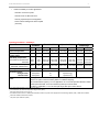
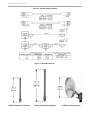
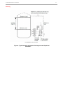
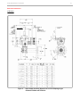
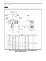
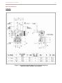
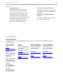
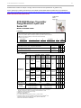
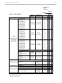
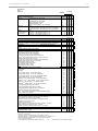
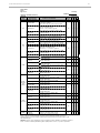
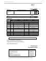
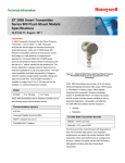
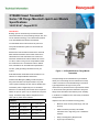
XYR6000 Smart Transmitter Series 100 Flange Mounted Liquid Level Models Specifications 34-XY-03-47 August 2012 Introduction Building upon the tremendously successful ST 3000 series transmitter line; Honeywell brings simple, safe, and secure wireless technology to its measurement portfolio in the XYR 6000 Series Wireless Transmitters. The XYR 6000 series measurements are part of the Honeywell OneWireless system and are ISA100.11a Compliant. Measurement and information without wires! The XYR 6000 wireless transmitter series enable customers to obtain data and create information from remote and hazardous measurement locations without the need to run wires, where running wire is cost prohibitive and/or the measurement is in a hazardous location. Without wires, transmitters can be installed and operational in minutes, quickly providing information back to your system. Figure 1 – XYR 6000 Wireless Flange Mount Transmitter XYR 6000 wireless transmitters send information to an ISA100.11a compliant MESH infrastructure. Wireless Data Managers (WDM) provides the path to bring that information into Experion PKS or any other control system wirelessly via OPC client or Modbus-TCP. Honeywell flange-mount transmitters may be installed directly onto a tank flange and are offered with a variety of tank connections to include ANSI flange connections. Typical applications are high accuracy level Transmitter power is supplied by two “D” size lithium measurement in pressurized and un-pressurized vessels batteries in an intrinsically safe module with an expected in the chemical and hydrocarbon industries. Honeywell lifetime of up to ten years or by an external 24 Vdc power flange mount transmitters demonstrate proven reliability supply. Transmitter range with the integral antenna is in hundreds on installations in a wide variety of industries 1000’ (305 m) under ideal conditions.. and applications. Implement the value of wireless technology today: Models STFW128 0 to 400 inH2O 0 to 1,000 mbar STFW132 0 to 100 psi 0 to 7bar STFW12F 0 to 400 inH2O 0 to 1,000 mbar STFW13F 0 to 100 psi 0 to 7 bar STFW14F 0 to 600 inH2O 0 to 1,500 mbar • Measure remote access points simply, safe and securely • Obtain and utilize previously inaccessible information due to high wiring cost or hazardous locations. • Easily meet Regulatory Requirements • Improve process efficiency XYR 6000 Wireless Transmitter • 2 Enhance Flexibility to monitor applications: - that have no access to power - that are remote or difficult to reach - that may require frequent reconfiguration - where manual readings have been required previously. Operating Conditions – All Models Parameter Reference Condition Rated Condition Transportation and Storage °C °F °F °C °F °C °F Ambient Temperature 25±1 77±2 -40 to 85 5 -40 to 1855 -40 to 855 -40 to 1855 -40 to 85 -40 to 185 Ambient Temperature LCD Display Visible 25±1 77±2 -40 to 855 -40 to 1855 -40 to 855 -40 to 1855 -40 to 85 -40 to 185 Meter Body Temperature All models except STFW14F STFW14F 25±1 25±1 77±2 77±2 -40 to 110 -40 to 85 -40 to 230 -40 to 185 1 -40 to 125 -40 to 85 -40 to 257 -40 to 185 -40 to 85 -40 to 85 -40 to 185 -40 to 185 Process Interface Temp. STFW128, STFW132 only 25±1 77±2 -40 to 1101 -40 to 2301 -40 to 1752 -40 to 3502 -40 to 85 -40 to 185 Humidity %RH Minimum Pressure mmHg absolute inH2O absolute Power °C Operative Limits 1 10 to 55 0 to 100 0 to 100 atmospheric atmospheric 25 13 2 (short term3) 3 1 (short term ) 0 to 100 Battery powered 3.6V Lithium thionyl chloride (LiSOCl2) batteries non rechargeable, size D. There is an option to have the battery fitted or not fitted for shipping. 24 Vdc Wired Power (option) - For I.S. Application: 21 V to 25 Vdc Operated with MTL7728P+ barrier (252 Ohms Max. end to end resistance), Max input current 26mA. For Non I.S. application: 11 V to 30 Vdc Input range, Max input current 100mA. 1 For CTFE fill fluid, the rating is –15 to 110 °C (5 to 230°F) 2 For CTFE fill fluid, the maximum temperature rating is 150°C (300°F) 3 Short term equals 2 hours at 70°C (158 °F) 4 The Ambient Limits shown are for Ordinary Non-Hazardous locations only. Refer to the appropriate Control Drawing, FM/CSA, ATEX, or IECEx for the Ambient Limits when installed in Hazardous Locations. 5 24V power option rated 80°C (176°F) XYR 6000 Wireless Transmitter 3 Maximum Allowable Working Pressure (MAWP) 3 (XYR 6000 products are rated to Maximum Allowable Working Pressure. MAWP depends on Approval Agency and transmitter materials of construction.) STFW128, STFW132 Flange Material Ambient Temperature -29 to 38°C [-20 to 100°F] Maximum Meterbody Temperature 125°C [257°F] Process Interface Temperature 175°C [350°F] ANSI Class 150 psi [ bar] Carbon Steel 304 S.S. 316 S.S. 285 [19.6] 275 [19.0] 275 [19.0] 245 [16.9] 218 [15.0] 225 [15.5] 215 [14.8] 198 [13.7] 205 [14.1] ANSI Class 300 psi [bar] Carbon Steel 304 S.S. 316 S.S. Carbon Steel 304 S.S. 316 S.S. 740 [51.0] 720 [49.6] 720 [49.6] 580 [40.0] 1 534 [36.8] 1 534 [36.8] 1 668 [46.0] 570 [39.3] 590 [40.7] 574 [39.6] 419 [28.9] 434 [29.9] 645 [44.5] 518 [35.7] 538 [37.1] 559 [38.5] 385 [26.5] 399 [27.5] 316L Stainless Steel 230 [15.9] 185 [12.8] No rating at this temp DN PN40 psi [bar] STFW12F, STFW13F, STFW14F ANSI Class 150 psi [bar] 1 Ambient Temperature for DN PN40 is –10 to 50°C [14 to 122 F] 3 MAWP applies for temperature range -40 to 125°C. Wireless Specifications Parameter Description Wireless Communication 2,400 to 2,483.5 MHz (2.4 GHz) Industrial, Scientific and Medical (ISM) band FHSS Selection – Frequency Hopping Spread Spectrum DSSS Selection – Direct Sequential Spread Spectrum per FCC 15.247 / IEEE 802.15.4–2006. ISA100.11a Compliant (2.4 GHz Direct Sequence Spread Spectrum 802.15.4 DSSS-FH) Every data packet transmitted in either direction is verified (CRC check) and acknowledged by the receiving device. USA – FCC Certified Canada – IC Certified European Union – RTTE/ETSI Conformity Japan – Ministry of Internal Affairs and Communications Certified (DSSS Selection only) ISA100.11a RF Transmitter Power (Optional) NA Selection – 125 mW (20.9 dBm) maximum transmit power not including antenna per FCC/IC, or 400 mW (26.0 dBm) maximum EIRP including antenna for USA and Canadian locations. EU Selection – 10 mW (10.0 dBm) maximum EIRP including antenna per RTTE/ETSI for EU locations. DSSS RF Transmitter Power (Optional) NA Selection – 125 mW (20.9 dBm) maximum transmit power not including antenna per FCC/IC, or 400 mW (26.0 dBm) maximum EIRP including antenna for USA and Canadian locations. EU Selection – 10 mW (10.0 dBm) maximum EIRP including antenna per RTTE/ETSI for EU locations. JP Selection – 12.14 dBm/MHz [32mW (15.14 dbm)] maximum EIRP including antenna for Japanese locations. Data PV Publish Cycle Time: Configurable as 1, 5, 10, 30 or 60seconds Rate: 250 Kbps Antennas Integral – 2 dBi omnidirectional monopole Integral – 4 dBi omnidirectional monopole Remote – 8 dBi omnidirectional monopole with up to 20 m cable and lightning surge arrester XYR 6000 Wireless Transmitter 4 Remote – 14 dBi directional parabolic with up to 20 m cable and lightning surge arrester. Signal Range Nominal 305 m (1,000 feet) between Field Transmitter and Infrastructure Unit (Multinode) or Gateway Unit when using 2 dBi Integral antenna with a clear line of sight.* Two XYR 6000 transmitters both having TX Power set to 16 dBm with a clear line of site nominal signal range is 150 m (490ft.) Routing vs NonRouting Unit can be set as a Field Routing or non-Field Routing device; the number of routing devices is set by the system manager. Using the device as a routing device will impact battery life, the more messages routed through a device, the greater the impact on battery life. *Actual range will vary depending on antennas, cables and site topography. XYR 6000 Wireless Transmitter 5 Figure 2 - Remote antenna cables Figure 3 - Remote Antennas 4 dBi Omnidirectional Antenna 8 dBi Omnidirectional Antenna 14 dBi Directional Antenna XYR 6000 Wireless Transmitter 6 Performance under Rated Conditions* - Model STFW128 (400 in H2O) Parameter Upper Range Limit Description in H2O mbar Lower Range Limit in H2O mbar Minimum Span in H2O mbar (Span can be between -400 to +400 inH20 / -1000 to +1000 mbar) Maximum Span in H2O mbar (400 inH20 / 1000mbar (span can be between -400 to +400 inH20) Zero Elevation and Suppression 400 (39.2°F/4°C is standard reference temperature for in H2O range.) 1,000 -400 (39.2°F/4°C is standard reference temperature for in H2O range.) -1,000 4 10 Accuracy (Reference – Includes combined effects of linearity, hysteresis, and repeatability) • Accuracy includes residual error after averaging successive readings. ±0.075% of calibrated span or upper range value (URV), whichever is greater, terminal based. For URV below reference point (25 in H2O), accuracy equals: Zero Temperature Effect per 28°C (50°F) ±0.20% of span. For URV below reference point (50 in H2O), effect equals: 50 inH2O 125 mbar ±0.20 span inH O or ±0.20 span mbar in % of span 2 400 1000 No limit except min. span within ±100% URL. Specifications valid from -5 to +100% URL. 25 inH 2 O or span inH O 2 ± 0.025 + 0.05 62.5 mbar in % of span span mbar ± 0.025 + 0.05 ( Combined Zero and Span Temperature Effect per 28°C (50°F) ±0.375% of span. For URV below reference point (50 in H2O), effect equals: 50 inH 2 O or span inH O 2 ± 0.175 + 0.20 Zero Static Pressure Effect per 300 psi (20 bar) 125 mbar in % of span span mbar ± 0.175 + 0.20 ±0.1625% of span. For URV below reference point (50 in H2O), effect equals: 50 inH 2 O or span inH O 2 ± 0.0125 + 0.15 Combined Zero and Span Static Pressure Effect per 300 psi (20 bar) ) 125 mbar in % of span span mbar ± 0.0125 + 0.15 ±0.30% of span. For URV below reference point (50 in H2O), effect equals: 50 inH 2 O or span inH O 2 ± 0.15 + 0.15 125 mbar in % of span span mbar ± 0.15 + 0.15 * Performance specifications are based on reference conditions of 25°C (77°F), zero (0) static pressure, 10 to 55% RH, and 316 Stainless Steel barrier diaphragm. XYR 6000 Wireless Transmitter 7 Performance under Rated Conditions* - Model STFW132 (100 psi) Parameter Description Upper Range Limit psi bar 100 7 Upper Range Limit psi bar -100 -7 Minimum Span psi bar 1 0.07 (Span can be between -400 to +400 inH20 / -1000 to +1000 mbar) Minimum Span psi bar (400 inH20 / 1000mbar (span can be between -400 to +400 inH20) 100 7 Zero Elevation and Suppression No limit except minimum span within –18 and +100% URL. Specifications valid from –5 to +100% URL. Accuracy (Reference – Includes combined effects of linearity, hysteresis, and repeatability) • Accuracy includes residual error after averaging successive readings. ±0.075% of calibrated span or upper range value (URV), whichever is greater, terminal based. For URV calibrated below reference point (20 psi), accuracy equals: Zero Temperature Effect per 28°C (50°F) ±0.20% of span. For URV below reference point (30 psi), effect equals: 30 psi 2 bar ±0.20 span psi or ±0.20 span bar in % of span span psi ( Combined Zero and Span Temperature Effect per 28°C (50°F) ) ( span psi in % of span ) 30 psi 2 bar span bar or ± 0.175 + 0.20 in % of span ±0.1625% of span. For URV below reference point (30 psi), effect equals: span psi ± 0.0125 + 0.15 Combined Zero and Span Static Pressure Effect per 300 psi (20 bar) 1.4 bar span bar or ± 0.025 + 0.05 ±0.375% of span. For URV below reference point (30 psi), effect equals: ± 0.175 + 0.20 Zero Static Pressure Effect per 300 psi (20 bar) 20 psi ± 0.025 + 0.05 30 psi 2 bar span bar or ± 0.0125 + 0.15 in % of span ±0.30% of span. For URV below reference point (30 psi), effect equals: span psi ± 0.15 + 0.15 30 psi 2 bar span bar or ± 0.15 + 0.15 in % of span * Performance specifications are based on reference conditions of 25°C (77°F), zero (0) static pressure, 10 to 55% RH, and 316 Stainless Steel barrier diaphragm. XYR 6000 Wireless Transmitter 8 Performance under Rated Conditions* - Model STFW12F (0 to 400 in H2O) Parameter Description Upper Range Limit in H2O mbar 400 (39.2°F/4°C is standard reference temperature for in H2O range.) 1,000 Minimum Span in H2O mbar 1 Note: Recommended minimum span in square root mode is 20 in H2O (50 mbar). 2.5 Zero Elevation and Suppression No limit except minimum span within ±100% URL. Specifications valid from –5 to +100% URL. Accuracy (Reference – Includes combined effects of linearity, hysteresis, and repeatability) • Accuracy includes residual error after averaging successive readings. • ±0.0625% of calibrated span or upper range value (URV), whichever is greater, terminal based. For URV below reference point (25 in in H2O), accuracy equals: Zero Temperature Effect per 28°C (50°F) ±0.05% of span. For URV below reference point (50 in H2O), effect equals: 50 inH2O 125 mbar ±0.05 span inH O or ±0.05 span mbar in % of span 2 25 inH 2 O or span inH O 2 ± 0.0125 + 0.05 ( Combined Zero and Span Temperature Effect per 28°C (50°F) or span inH 2 O 50 inH 2 O 125 mbar in % of span span mbar ± 0.025 + 0.05 ±0.075% of span. For URV below reference point (50 in H2O), effect equals: or 125 mbar in % of span ± 0.0125 + 0.0625 span inH O span mbar 2 ± 0.0125 + 0.0625 Combined Zero and Span Static Pressure Effect per 1000 psi (70 bar)• ) ±0.075% of span. For URV below reference point (50 in H2O), effect equals: ± 0.025 + 0.05 Zero Static Pressure Effect per 1000 psi (70 bar) 62 mbar in % of span span mbar ± 0.0125 + 0.05 50 inH 2 O ±0.15% of span. For URV below reference point (50 in H2O), effect equals: 50 inH 2 O 125 mbar or ± 0.0875 + 0.0625 in % of span span inH O span mbar 2 ± 0.0875 + 0.0625 * Performance specifications are based on reference conditions of 25°C (77°F), zero (0) static pressure, 10 to 55% RH, and 316 Stainless Steel barrier diaphragm. XYR 6000 Wireless Transmitter 9 Performance under Rated Conditions* - Model STFW13F (0 to 100 psi) Parameter Description Upper Range Limit psi bar 100 7 Minimum Span psi bar 1 0.07 Zero Elevation and Suppression No limit except minimum span within –18 and +100% URL. Specifications valid from –5 to +100% URL. Accuracy (Reference – Includes combined effects of linearity, hysteresis, and repeatability) • Accuracy includes residual error after averaging successive readings. • ±0.0625% of calibrated span or upper range value (URV), whichever is greater, terminal based. For URV below reference point (15 psi), accuracy equals: Zero Temperature Effect per 28°C (50°F) ±0.05% of span. For URV below reference point (30 psi), effect equals: span ± 0.0125 + 0.05 ± 0.05 Combined Zero and Span Temperature Effect per 28°C (50°F) or psi 30 psi span 1 bar in % of span span bar in % of span span bar ± 0.05 span or psi 30 psi 2 bar span ± 0.025 + 0.05 in % of span bar 2 bar ±0.075% of span. For URV below reference point (30 psi), effect equals: ± 0.0125 + 0.0625 Combined Zero and Span Static Pressure Effect per 1000 psi (70 bar) ± 0.0125 + 0.05 ±0.075% of span. For URV below reference point (30 psi), effect equals: ± 0.025 + 0.05 Zero Static Pressure Effect per 1000 psi (70 bar) or psi 15 psi or psi 30 psi span span bar ± 0.0125 + 0.0625 2 bar in % of span ±0.15% of span. For URV below reference point (30 psi), effect equals: span ± 0.0875 + 0.0625 or psi 30 psi span ± 0.0875 + 0.0625 in % of span bar 2 bar * Performance specifications are based on reference conditions of 25°C (77°F), zero (0) static pressure, 10 to 55% RH, and 316 Stainless Steel barrier diaphragm. XYR 6000 Wireless Transmitter 10 Performance under Rated Conditions* - Model STFW14F (0 to 600 inH2O) Parameter Description Upper Range Limit inH2O mbar 600 (39.2°F/4°C is standard reference temperature for inH2O range.) 1,500 Minimum Span inH2O mbar 6 15 Zero Elevation and Suppression No limit except minimum span within 0 to 100% URL. Accuracy (Reference – Includes combined effects of linearity, hysteresis, and repeatability) • Accuracy includes residual error after averaging successive readings. ±0.05% of calibrated span or upper range value (URV), whichever is greater, terminal based. For URV below reference point (25 inH2O), accuracy equals: Zero Temperature Effect per 28°C (50°F) ±0.05% of span. For URV below reference point (50 inH2O), effect equals: 25 inH 2O or span inH O 2 ± 0.0125 + 0.0375 or span inH O 2 ± 0.05 Combined Zero and Span Temperature Effect per 28°C (50°F) 50 inH 2 O span in % of span mbar 62 mbar in % of span span mbar ± 0.05 125 mbar or span inH 2 O 50 inH 2 O 125 mbar in % of span span mbar ± 0.025 + 0.05 ±0.075% of span. For URV below reference point (50 inH2O), effect equals: or 125 mbar in % of span ± 0.0125 + 0.0625 span inH O span mbar 2 ± 0.0125 + 0.0625 Combined Zero and Span Static Pressure Effect per 1000 psi (70 bar) ±0.075% of span. For URV below reference point (50 inH2O), effect equals: ± 0.025 + 0.05 Zero Static Pressure Effect per 1000 psi (70 bar) ± 0.0125 + 0.0375 50 inH 2 O ±0.20% of span. For URV below reference point (50 inH2O), effect equals: 50 inH 2 O or span inH O 2 ± 0.1375 + 0.0625 125 mbar in % of span span mbar ± 0.1375 + 0.0625 * Performance specifications are based on reference conditions of 25°C (77°F), zero (0) static pressure, 10 to 55% RH, and 316 Stainless Steel barrier diaphragm. XYR 6000 Wireless Transmitter 11 Performance under Rated Conditions - General for all Models Parameter Lightning Surge Arrester (Remote antenna only) CE Conformity Hazardous Location Description Frequency range: 0 – 3 GHz, 50 Ohms, VSWR = 1:1.3 Max, Insertion Loss = 0.4 dB Connectors Type N Female, Max, Gas Tube Element: 90 V ± 20%, Impulse Breakdown Voltage = 1,000 V ± 20%, Maximum Withstand Current = 5 KA. These transmitters are in conformity with the protection requirements of European Council Directives: 89/336/EEC, the EMC Directive and 1999/5/EC, the Telecommunications Directive per EN 300 328 V1.7.1, EN301 893 V1.3.1, EN301 48917 V1.2.1, EN301 489-1 V1.6.1 and EN61326-1 (1st Edition, 2002-02, Industrial Locations). Electrical Equipment for Measurement, Control and Laboratory Use – EMC Requirements. Certifications: See the Model Selection Guide on page 12. Physical and Approval Bodies Parameter Barrier Diaphragms Material (Wetted) Gasket Ring Material (Wetted) Extension Tube Material Process Head and Adapter Flange Material Process Head Gaskets Meter Body Bolting Mounting Flange STFW128, STFW132 STFW12F, STFW13F, STFW14F Fill Fluid Electronic Housing Process Connections All Models STFW128, STFW132 STFW12F, STFW13F, STFW14F Mounting Dimensions Net Weight STFW128, STFW132 STFW12F, STFW13F, STFW14F 2 Description 316L SS, Hastelloy® C-276*2, Monel®400**3 316/316L SS, Hastelloy® C-276*2, Monel®400**3 316 SS 316 SS4, Carbon Steel (Zinc-plated) 5, Monel®400**7, Hastelloy® C-276*6 Teflon® is standard. Viton® is optional Carbon Steel (Zinc-plated) or 316 SS (NACE) bolts. Flush or Extended Diaphragm: Zinc plated Carbon Steel, 304 SS, or 316 SS 316L SS (NOTE: Mounting Flange is process wetted.) DC® 200 Silicone oil or CTFE (Chlorotrifluoroethylene) Epoxy-Polyester hybrid paint. Low Copper-Aluminum. Meets NEMA 4X (watertight) and NEMA 7 (explosion proof). Stainless Steel optional. Process Head: 1/4-inch NPT; 1/2-inch NPT with adapter and DIN, standard options. Flange: 2, 3 or 4-inch Class 150 or 300 ANSI; DN50-PN40, DN80-PN40 or DN100-PN40 DIN flange. Extended Diaphragm: 2, 4, or 6 inches (50, 101, 152 mm) long. 2 or 3-inch, Class 150 ANSI flange. See Figure 4 for typical flange mounting arrangement. See Figure 5, Figure 6, and Figure 7 Flush or Extended Model: 15.5 to 35.0 pounds (7 to 16 Kg) depending on flange size8 8 14.2 to 18.4 pounds (6.5 to 9 Kg) depending on flange size ® Hastelloy C-276 or UNS N10276 ® Monel 400 or UNS N04400 4 Supplied as 316 SS or as Grade CF8M, the casting equivalent of 316 SS. 5 Carbon Steel heads are zinc-plated and not recommended for water service due to hydrogen migration. For that service, use 316 stainless steel wetted Process Heads. 6 ® ® Hastelloy C-276 or UNS N10276. Supplied as indicated or as Grade CW12MW, the casting equivalent of Hastelloy C-276 7 ® ® Monel 400 or UNS N04400. Supplied as indicated or as Grade M30C, the casting equivalent of Monel 400 8 Add 8.0 pounds (3.6 kg) to any model equipped with the stainless steel housing option. (Model Selection Guide Table IV selections A3 or SH) * Flush design only. **Flush or pseudo flange design. 3 NOTE: Pressure transmitters that are part of safety equipment for the protection of piping (systems) or vessel(s) from exceeding allowable pressure limits, (equipment with safety functions in accordance with Pressure Equipment Directive 97/23/EC article 1, 2.1.3), require separate examination. XYR 6000 Wireless Transmitter 12 Certifications MSG CODE AGENCY TYPE OF PROTECTION Intrinsically Safe: Class I; Division 1; Groups A, B, C, D; Class II, Division 1, Groups E, F, G; Class III, Division 1; T4 Class I, Zone 0 Ex ia IIC T4 Class I, Zone 0 AEx ia IIC T4 Nonincendive: Class I; Division 2; Groups A, B, C, D; Class II, Division 2, Groups F, G; Class III, Division 2, T4 2C CSA 1903673 (USA and Canada) Class I, Zone 2 Ex nA IIC, T4 Class I, Zone 2 AEx nA IIC, T4 Explosion-Proof/ Flameproof: Class I, Division 1; Groups A, B, C, D; Class II, Division 1, Groups E, F, G; Class III, Division 1; T4 Class I, Zone 1 Ex d IIC T4 Class I, Zone 1 AEx d IIC, T4 Ambient Temperature -40 oC to +85 oC : Battery o o -40 C to +80 C : DC Supply Enclosure: Type 4X/ IP66 Intrinsically Safe: Class I; Division 1; Groups A, B, C, D; Class II, Division 1, Groups E, F, G; Class III, Division 1; T4 1C FM ApprovalsTM 3032450 (USA) ATEX- KEMA 08ATEX0062X 3C ATEX- DEKRA 08ATEX0074 Class I, Zone 0 AEx ia IIC T4 Nonincendive: Class I; Division 2; Groups A, B, C, D; Class II, Division 2, Groups F, G; Class III, Division 2, T4 Class I, Zone 2 AEx nA IIC, T4 Explosion-Proof/ Flameproof: Class I, Division 1; Groups A, B, C, D; Class II, Division 1, Groups E, F, G; Class III, Division 1; T4 Class I, Zone 1 AEx d IIC, T4 Ambient Temperature -40 oC to +85 oC : Battery o o -40 C to +80 C : DC Supply Enclosure: Type 4X/ IP66 Intrinsically Safe: II 1 G Ex ia IIB T4 o II 1 D Ex tD A20 IP66 T90 C Flameproof: II 2 G Ex d [ia] IIB T4 II 2 D Ex tD A21 IP66 T90 oC Ambient Temperature -40 oC to +70 oC : Battery -40 oC to +80 oC : DC Supply Enclosure: IP66 Nonincendive: II 3 G Ex nA [nL] IIC T4 o II 3 D Ex tD A22 IP66 T90 C Ambient Temperature -40 oC to +84 oC : Battery o o -40 C to +80 C : DC Supply Enclosure: IP66 XYR 6000 Wireless Transmitter MSG CODE AGENCY C1 IECEx- CSA 09.0001X ZC SAEx S/09-036X (South Africa) 6C INMETRO* NCC 11.0331 X (BRAZIL) 13 TYPE OF PROTECTION Intrinsically Safe: Ex ia IIB T4 o Ex tD A20 IP66 T90 C Flameproof: Ex d [ia] IIB T4 Ex tD A21 IP66 T90 oC Nonincendive: Ex nA [nL] IIC T4 Ex tD A22 IP66 T90 oC Ambient Temperature -40 oC to +70 oC (Ex ia, Ex d) -40 oC to +84 oC (Ex nA) : Battery o o -40 C to +80 C : DC Supply Enclosure: IP66 Intrinsically Safe: Ex ia IIB T4 o Ex tD A20 IP66 T90 C Flameproof: Ex d [ia] IIB T4 Ex tD A21 IP66 T90 oC Nonincendive: Ex nA [nL] IIC T4 Ex tD A22 IP66 T90 oC Ambient Temperature -40 oC to +70 oC (Ex ia, Ex d) -40 oC to +84 oC (Ex nA) : Battery o o -40 C to +80 C : DC Supply Enclosure: IP66 Intrinsically Safe: Ex ia IIB T4 Ga Flameproof: Ex d [ia] IIB T4 o Ex tb IIIC T90 C IP66 Nonincendive: Ex nA [ic] IIC T4 o Ex tc IIIC T90 C IP66 Ambient Temperature -40 oC to +70 oC (Ex ia, Ex d) -40 oC to +84 oC (Ex nA) : Battery -40 oC to +80 oC : DC Supply Enclosure: IP66 * At time of Printing Certification was pending Electrical Data Battery Two in series connected (D size) Lithium batteries, type 5930 manufactured by Tadiran, type XL-205F manufactured by Zeno Energy or type PT-2300H manufactured by Eagle Picher. Additionally for ATEX and IECEx certifications, Lithium Battery SL-2780, manufactured by Tadiran, GmbH may be used. DC Supply For Ordinary Locations, Explosion-proof and Non Incendive: 16.0 V min to 28.0 V max, Current = 100 mA For Intrinsically Safe: A Barrier, MTL 728P+ or MTL 7728P+ mounted in a suitable enclosure, or in a non-hazardous location is needed, see Agency Certification drawings in Section 6. XYR 6000 Wireless Transmitter 14 Mounting Error! Reference source not found. Figure 4 - Typical mounting arrangement for flange mounted liquid level transmitter. XYR 6000 Wireless Transmitter Reference Dimensions millimeters inches 149.4 / 168.9 588 / 6.65 Figure 5 - - Approximate mounting dimensions for flush diaphragm type models STFW128 and STFW132. 15 XYR 6000 Wireless Transmitter Reference Dimensions millimeters inches Figure 6 - - Approximate mounting dimensions for extended diaphragm type models STFW128 and STFW132 16 XYR 6000 Wireless Transmitter Reference Dimensions millimeters inches Figure 7 - Approximate mounting dimensions for pseudo flange type models STFW12F, STFW13F, and STFW14F. 17 XYR 6000 Wireless Transmitter 18 Options • Tagging (Option TG) • Transmitter Configuration (Option TC) Up to 30 characters can be added on the All configurable parameters are accessible via stainless steel nameplate mounted on the the OneWireless network via READ/WRITE transmitter’s electronics housing at no extra cost. Note that a separate nameplate on the meter body contains the serial number and body-related data. A stainless steel wired on tag with additional data of up to 4 lines of 28 characters is also available. The number of transactions. • Custom Calibration and ID in Memory (Option C) The factory can calibrate any range within the scope of the transmitter’s range. characters for tagging includes spaces. Ordering information Sales and Service For application assistance, current specifications, pricing, or name of the nearest Authorized Distributor, contact one of the offices below. ASIA PACIFIC EMEA NORTH AMERICA SOUTH AMERICA (TAC) [email protected] Honeywell Process Solutions, Phone: + 80012026455 or +44 (0)1202645583 FAX: +44 (0) 1344 655554 Email: (Sales) [email protected] or (TAC) [email protected] Honeywell Process Solutions, Phone: 1-800-423-9883 Or 1-800-343-0228 Honeywell do Brasil & Cia Phone: +(55-11) 7266-1900 FAX: +(55-11) 7266-1905 Email: (Sales) [email protected] or (TAC) [email protected] Email: (Sales) [email protected] or (TAC) [email protected] Australia Honeywell Limited Phone: +(61) 7-3846 1255 FAX: +(61) 7-3840 6481 Toll Free 1300-36-39-36 Toll Free Fax: 1300-36-04-70 China – PRC - Shanghai Honeywell China Inc. Phone: (86-21) 5257-4568 Fax: (86-21) 6237-2826 Singapore Honeywell Pte Ltd. Phone: +(65) 6580 3278 Fax: +(65) 6445-3033 South Korea Honeywell Korea Co Ltd Phone: +(822) 799 6114 Fax: +(822) 792 9015 XYR 6000 Wireless Transmitter 19 Model Selection Guides are subject to change and are inserted into the specifications as guidance only. Prior to specifying or ordering a model check for the latest revision Model Selection Guides which are published at: https://www.honeywellprocess.com/en-US/explore/products/wireless/input-output-devices/xyr-6000/Pages/default.aspx Model Selection Guide (34-XY-16-23) 34-XY-16U-23 Issue 1 Page 1 of 5 XYR 6000 Wireless Transmitter Flange Mounted Liquid Level Series 100 Model Selection Guide Instructions ● ● ● ● ● Select the desired Key Number. The arrow to the right marks the selection available. Make one selection from each table, I, II and III, using the column below the proper arrow. Select as many Table IV options as desired (if no options or approvals are desired, specify 9X). A ( ) denotes unrestricted availability. A letter denotes restricted availability. Restrictions follow Table VI. Key Number _______ I - II ___ _____ - - III IV (Optional) _____ _ _, _ _, _ _ V - ____ VI - XXXX KEY NUMBER Span 0-4" to 0-400" H2O / 0-10 to 0-1,000 mbar - Compound Characterized 0-1 to 0-100 psi / 0-0.07 to 7 bar - Compound Characterized 0-1" to 0-400" H2O / 0-2.5 to 0-1,000 mbar 0-1 to 0-100 psi / 0-0.07 to 0-7 bar 0-6" to 0-600" H2O / 0-15 to 0-1,500 mbar Selection Availability STFW128 STFW132 STFW12F STFW13F STFW14F TABLE I - METER BODY Design Ref. Head Vent Drain Barrier Diaphrm. Valve on Ref. Head 2 (wetted) Diaphrm. Plate (wetted) Extension (wetted) 316L SS Carbon 1 Steel 316 SS Flush Materials of Construction Extended 316 SS 5 Hast C 3, 6 Hast C 3 Monel 400 4 7 Monel 40010 Carbon 1 Steel 316 SS Pseudo Flange Process Connection 1 Hast C 3 Hast C 3 Monel 400 4 Monel 400 4 Hast C 3 Hast C 3 Monel 400 4 Monel 400 4 316L SS Hast C 3 316L SS 316L SS 316 SS 5 Hast C 3 Monel 400 4 316L SS Hast C 3 Monel 400 4 316L SS N/A ® DC 200 Silicone CTFE Reference Head 1/4 NPT 1/4 NPT 1/2 NPT (with Adapter) 1/2 NPT (with Adapter) Flange High Pressure Side Low Pressure Side High Pressure Side Low Pressure Side Carbon Steel heads are zinc-plated and not recommended for water service due to hydrogen migration. For that service, use the 316 stainless steel Wetted Reference Head. Vent/Drains are Teflon or PTFE coated for lubricity. 3 Hastelloy® C-276 or UNS N10276 4 Monel 400® or UNS N04400 5 Supplied as 316SS or as Grade CF8M, the casting eguivalent of 316SS 6 Supplied as indicated or as Grade CW12MW, the casting equivalent of Hastelloy® C-276 7 Supplied as indicated or as Grade M30C, the casting equivalent of Monel 400® 10 Monel 400® or UNS N04400 or UNS N04405 2 N/A Hast C 3 316L SS Carbon 1 Steel 316 SS Fill Fluid (Meter Body & 316 SS 5 316L SS 316L SS Hast C 3 3 Hast C Hast C 3 4 Monel 400 Monel 400 4 316L SS 316L SS 316L SS Hast C 3 N/A Sel. A__ W__ B__ C__ E__ X__ F__ G__ J__ L__ M__ N__ R__ S__ A__ B__ C__ E__ F__ G__ _1_ _2_ Sel. __A __C __H __K ● ● ● r ● ● ● r ● r ● ● ● ● ● ● ● r ● ● ● r ● ● ● ● ● ● ● ● ● ● t t t t t XYR 6000 Wireless Transmitter 20 34-XY-16U-23 Issue 1 Page 2 of 5 Availability STFW1xx TABLE II - FLANGE ASSEMBLY Flange Material None No Selection Flange (ANSI Flanges have 125-500 AARH Surface Finish) 3" ANSI Class 150 3" ANSI Class 300 DN80-PN40 DIN 4" ANSI Class 150 Carbon Steel 4" ANSI Class 300 (non-wetted) DN100-PN40 DIN 2" ANSI Class 150 2" ANSI Class 300 DN50-PN40 DIN 3" ANSI Class 150 3" ANSI Class 300 DN80-PN40 DIN 4" ANSI Class 150 304 SS 4" ANSI Class 300 (non-wetted) DN100-PN40 DIN 2" ANSI Class 150 2" ANSI Class 300 DN50-PN40 DIN 3" ANSI Class 150 3" ANSI Class 300 DN80-PN40 DIN 4" ANSI Class 150 316 SS 4" ANSI Class 300 (non-wetted) DN100-PN40 DIN 2" ANSI Class 150 2" ANSI Class 300 DN50-PN40 DIN Pseudo Flange on Standard DP 2" ANSI Class 150 without Vent/Drain 316L SS (wetted) 2" ANSI Class 150 with Vent/Drain 3" ANSI Class 150 without Vent/Drain 316L SS (wetted) 3" ANSI Class 150 with Vent/Drain No Selection Threaded Nut Ring Material None Carbon Steel (non-wetted) 304 SS (non-wetted) 304 SS (non-wetted) Monel 400® 4 316/316L SS Diameter Extension (wetted) 1.87 Inches (for 2", 3" or 4 " spud) No Selection 3 4 No Selection Hastelloy® C-276 or UNS N10276 Monel 400® or UNS N04400 2F 3F 4F 0____ _1___ _2___ _3___ _4___ _5___ _6___ _7___ _8___ _9___ _A___ _B___ _C___ _D___ _E___ _F___ _Q___ _U___ _V___ _H___ _J___ _K___ _L___ _M___ _N___ _W___ _X___ _Y___ ● ● ● ● ● ● ● ● ● ● ● ● ● ● ● ● ● ● ● ● ● ● ● ● ● ● ● ● ● ● _S___ ● ● _T___ ● ● _P___ ● ● _R___ ● ● ● ● ● ● ● ● Not Applicable Hastelloy® C 3 Extended Design No Selection Flush 28 32 Not Applicable 316L SS Gasket Ring (wetted) Flush Design Selection Length 2 inches 4 inches 6 inches __0__ __1__ __2__ __3__ __5__ ___0_ ___F_ ___C_ ___D_ ___E_ ____0 g g q v h v v v ● XYR 6000 Wireless Transmitter 21 34-XY-16U-23 Issue 1 Page 3 of 5 Availability STFW1xx 28 32 2F 3F 4F d d d d d d d d d e e d e e d e e d 28 32 2F 3F 4F XD XS b 00 BA DC b CC TC A1 A2 A3 SH TG ● ● ● ● ● ● f i f i f i ● ● ● ● ● ● ● b ● ● TB SP PG TL GE ● ● ● ● ● ● ● ● ● ● ● ● ● ● ● b CR SS B7 S2 S3 S4 S5 T2 T3 V2 V3 B3 B4 B5 B6 VT VF ● ● ● ● ● ● ● ● ● b c c c c c c c c c c c c c c c c c c c c c c c c ● ● ● ● ● ● ● ● ● ● ● ● ● ● ● m m m UM 0X TP F1 F3 F5 F7 FG FX ● ● ● j j j ● ● ● ● ● ● ● ● ● ● ● ● b k k k ● ● ● ● ● ● b W1 W2 ● ● ● ● ● ● TABLE III - ANTENNA OPTIONS Antenna's Integral Right-angle, vertical 2dBi Integral Straight, horizontal 2dBi Integral Right-angle, vertical 4dBi Remote Omnidirectional, 8 dBi Remote Directional, 14 dBi Remote Antenna Adapter, Type N Connection Cable A for None Remote Antenna 1.0m remote Cable A, Type N (Req'd to connect to XYR 6000) 3.0m remote Cable A, Type N (Req'd to connect to XYR 6000) 10.0m remote Cable A, Type N (Req'd to connect to XYR 6000) Cable B None for Remote Antenna Accessory + 1.0m Cable B to Antenna, N - N w/Accessories* Accessory + 3.0m Cable B to Antenna, N - N Accessory + 10.0m Cable B to Antenna, N - N Selection V____ S____ R____ M____ D____ A____ _00_ _ _21__ _23__ _29__ ___00 ___01 ___03 ___10 TABLE IV - OPTIONS Radio Options (Must Choose a Radio Option) 2.4 GHz Direct Sequence Spread Spectrum (802.15.4 DSSS-FH) ISA 100.11a Compliant (2.4 GHz Direct Sequence Spread Spectrum 802.15.4 DSSS-FH) Power Option (Must Choose Power Option) Battery Holder Only - No Battery Included Battery Power 24VDC Transmitter Housing & Electronics Options Custom Calibration and I.D. in Memory Transmitter Configuration and I.D. in Memory M20 Conduit Thread (1/2" NPT is standard) 1/2" NPT to 3/4" NPT 316 SS Conduit Adapter 5,9 316 SS Housing with 1/2" NPT Conduit Connection 5,9 316 SS Electronics Housing - with M20 Conduit Connections Stainless Steel Customer Wired-On Tag (4 lines, 28 characters per line, customer supplied information) Stainless Steel Customer Wired-On Tag (blank) End Cap Warning Label in Spanish End Cap Warning Label in Portuguese End Cap Warning Label in Italian End Cap Warning Label in German Process Head Options (Carbon Steel standard) NACE A286 SS Bolts 316 SS Bolts B7M Bolts 5 316 SS Adapter Flange - 1/2" NPT with CS Bolts 5 316 SS Adapter Flange - 1/2" NPT with 316 SS Bolts 5 316 SS Adapter Flange - 1/2" NPT with NACE A286 SS Bolts 5 316 SS Adapter Flange - 1/2" NPT with B7M Bolts ® 3, 6 Hastelloy C-276 Adapter Flange - 1/2" NPT with CS Bolts ® 3, 6 Hastelloy C-276 Adapter Flange - 1/2" NPT with 316 SS Bolts ® 4, 7 Monel 400 Adapter Flange - 1/2" NPT with CS Bolts ® 4, 7 Monel 400 Adapter Flange - 1/2" NPT with 316 SS Bolts 5 316 SS Blind Adapter Flange with CS Bolts 5 316 SS Blind Adapter Flange with 316 SS Bolts 5 316 SS Blind Adapter Flange with NACE A286 SS Bolts 5 316 SS Blind Adapter Flange with B7M Bolts ®8 Viton Process Head Gaskets (adapter gaskets ordered separately) ®8 Viton Adapter Flange Gaskets Services/Certificates/Marine Type Approval Options User's Manual Paper Copy (Standard, HC/H6, or FF ships accordingly) Clean Transmitter for Oxygen or Chlorine Service with Certificate Over-Pressure Leak Test with F3392 Certificate Calibration Test Report and Certificate of Conformance (F3399) Certificate of Conformance (F3391) Certificate of Origin (F0195) NACE Certificate (Process-Wetted & Non-Process Wetted) (FC33339) NACE Certificate (Process-Wetted Only) (FC33338) Material Traceability Certification per EN 10204 3.1 (FC33341) Warranty Options Additional Warranty - 1 year Additional Warranty - 2 years Selection 3 4 5 6 7 8 9 b b b b Table IV continued next page Hastelloy C-276 or UNS N10276 Monel 400® or UNS N04400 Supplied as 316 SS or as Grade CF8M, the casting equivalent of 316 SS. Supplied as indicated or as Grade CW12MW, the casting equivalent of Hastelloy® C-276 Supplied as indicated or as Grade M30C, the casting equivalent of Monel 400® Viton® or Fluorocarbon Elastomer If ordered with Remote Antenna option, Table III Selection M _ _ _ _ or D _ _ _ _, antenna parts are not SS or Marine type cables ® b XYR 6000 Wireless Transmitter 22 34-XY-16U-23 Issue 1 Page 4 of 5 Availability STFW1xx TABLE IV - OPTIONS (continued) Approval Body Approval Type No hazardous location approvals Intrinsically Safe FM Explosion-proof Nonincendive Non-Sparking Nonincendive Non-Sparking Intrinsically Safe CSA cus Explosion-proof Nonincendive Non-Sparking Intrinsically Safe Flameproof Non-Sparking ATEX Intrinsically Safe Flameproof Non-Sparking Intrinsically Safe Flameproof IECEx Non-Sparking Australia & New Zealand Intrinsically Safe Flameproof Non-Sparking Intrinsically Safe Flameproof SAEx South Africa Non-Sparking Intrinsically Safe Flameproof Non-Sparking INMETRO Intrinsically Safe Flameproof Brazil Non-Sparking Location or Classification Class I, II, III, Div. 1, Groups A,B,C,D,E,F,G; T4, Ta ≤ 85°C; Type 4X Class I, AEx ia IIC; T4, Ta ≤ 85°C, Zone 0; IP66 Class I, Div. 1, Groups A,B,C,D; Cl II, Div. 1,Groups E, F & G; Cl III, Div. 1, T4, Ta ≤ 85°C; Type 4X Class I, AEx d IIC; T4, Ta ≤ 85°C, Zone 1; IP66 Class I, Div. 2, Groups A,B,C,D; T4, Ta ≤ 85°C; Type 4X Class I, AEx nA IIC; T4, Ta ≤ 85°C, Zone 2; IP66 Nonincendive, CL I, Div 2, Groups A,B,C & D, CL II & III, Div 2, Groups F & G, T4 Ta = 85°C Class I, Ex/AEx nA IIC; T4, Ta ≤ 85°C, Zone 2; IP66 Class I, Div. 1, Gp A,B,C,D; Class II, Div 1, Gp E,F,G; Class III, Div 1; T4, Ta ≤ 85°C; Type 4X Class I, Ex/AEx ia IIC; T4, Ta ≤ 85°C, Zone 0; IP66 Class I, Div. 1, Groups A,B,C,D; Class II, Div. 1,Groups E, F & G; Class III, Div. 1, T4, Ta ≤ 85°C; Type 4X Class I, Ex/AEx d IIC; T4, Ta ≤ 85°C, Zone 1; IP66 Class I, Div. 2, Groups A,B,C,D; T4, Ta ≤ 85°C; Type 4X Class I, Ex/AEx nA IIC; T4, Ta ≤ 85°C, Zone 2; IP66 II 1 GD; Ex ia IIB; T4, Ta ≤ 70°C, Zone 0; IP66 Ex tD A20 IP66 T90ºC II 2 GD; Ex d [ia] IIB; T4, Ta ≤ 70°C, Zone 1; IP66 Ex tD A21 IP66 T90ºC II 3 GD; Ex nA [nL] IIC; T4, Ta ≤ 84°C, Zone 2 Ex tD A22 IP66 T90ºC II 1 GD; Ex ia IIB; T4, Ta ≤ 70°C, Zone 0; IP66 Ex tD A20 IP66 T90ºC II 2 GD; Ex d [ia] IIB; T4, Ta ≤ 70°C, Zone 1; IP66 Ex tD A21 IP66 T90ºC II 3 GD; Ex nA [nL] IIC; T4, Ta ≤ 84°C, Zone 2 Ex tD A22 IP66 T90ºC Ex ia IIB; T4, Ta ≤ 70°C, Zone 0; IP66 Ex tD A20 IP66 T90ºC Ex d [ia] IIB; T4, Ta ≤ 70°C, Zone 1; IP66 Ex tD A21 IP66 T90ºC Ex nA IIC; T4, Ta ≤ 84°C, Zone 2; IP66 Ex tD A22 IP66 T90ºC Ex ia IIB; T4, Ta ≤ 70°C, Zone 0; IP66 Ex tD A20 IP66 T90ºC Ex d [ia] IIB; T4, Ta ≤ 70°C, Zone 1; IP66 Ex tD A21 IP66 T90ºC Ex nA [nL] IIC; T4, Ta ≤ 84°C, Zone 2; IP66 Ex tD A22 IP66 T90ºC Ex ia IIB; T4, Ta ≤ 70°C, Zone 0; IP66 Ex tD A20 IP66 T90ºC Ex d [ia] IIB; T4, Ta ≤ 70°C, Zone 1; IP66 Ex tD A21 IP66 T90ºC Ex nA [nL] IIC; T4, Ta ≤ 84°C, Zone 2; IP66 Ex tD A22 IP66 T90ºC Ex ia IIB; T4, Ta ≤ 70°C, Zone 0; IP66 Ex tD A20 IP66 T90ºC Ex d [ia] IIB; T4, Ta ≤ 70°C, Zone 1; IP66 Ex tD A21 IP66 T90ºC Ex nA [nL] IIC; T4, Ta ≤ 84°C, Zone 2; IP66 Ex tD A22 IP66 T90ºC Ex ia IIC; T4, Ta ≤ 85°C, Zone 0; IP 66 Ex d IIC; T4, Ta ≤ 85°C, Zone 1; IP 66 Ex nA IIC; T4, Ta ≤ 85°C, Zone 2; IP 66 28 2F 32 3F 1C 2N 2C 3U 3B 3Y 3C* CU CB CY C1* ZU ZB ZY ZC* 6C* Selection 9X 4F b * The user must determine the type of protection required for installation of the equipment. The user shall then check the box [√] adjacent to the type of protection used on the equipment certification nameplate. Once a type of protection has been check on the nameplate, subsequently the equipment shall not be reinstalled using any of the other certification types. WARNING – Division 2 / Zone 2 apparatus may only be connected to processes classified as non-hazardous or Division 2 / Zone 2. Connection to hazardous (flammable or ignition capable) Division 1 / Zone 0, or 1 process is not permitted. XYR 6000 Wireless Transmitter 23 34-XY-16U-23 Issue 1 Page 5 of 5 Availability TABLE V Country North America, Canada European Union Japan Brazil STFW1xx Selection (Must Choose a Country Code) Country Code NA00 EU00 JP00 BZ00 Selection XXXX TABLE VI Factory Identification ● ● ● RESTRICTIONS Restriction Letter b c d e f g Table I III I h Available Only With Not Available With Selection Table Selection Select only one option from this group _ _ H, _ _ K _ 00 _ _ , _ _ _ 00 III _ 00 _ _ IV SH, A3 A _ _, B _ _, E _ _, F _ _, J _ _, W _ _, X _ _ I M _ _,N _ _,R _ _,S _ _ II _ _ 5, _ _, _ _ 0 _ _ 1C or 2J IV BA, SH, A1 _2_ S2, S3, S5, T2, T3, B3, B4, B6, CR III V2, V3 i j III I k III m n q r t v III VT I C _ _, G _ _, L _ _ I Select S2,S3,S4,S5,T2,T3,V2,V3 M _ _, N _ _, R _ _, S _ _ III 1C, 2J IV F7, FG Ordering Example: STFW128-A1A-01000-R0000-XS,BA,1C-NA00-XXXX Hastelloy® is a registered trademark of Haynes International Monel 400® is a registered trademark of Special Metals Corporation. HART® is a registered trademark of HART Communication Foundation. FOUNDATIONTM Fieldbus is a registered trademark of Fieldbus Foundation. Viton® is a registered trademark of DuPont Performance Elastomers. Teflon® is a registered trademark of DuPont. FM ApprovalsSM is a service mark of FM Global Supplemental Accessories & Kits Description 1/2 NPT Socket Plug (ZN Plated CS) 1/2 NPT Certified Conduit Plug (SS) M20 Certified Conduit Plug (SS) M20 Conduit Plug (ZN Plated CS) Surge Diverter* Lithium Thionyl Chloride Batteries (Qty 2) Lithium Thionyl Chloride Batteries (Qty 4) Lithium Thionyl Chloride Batteries (Qty 10) Part Number 50021832-001 50021832-002 50000547-001 50000547-002 50018279-090 50026010-501 50026010-502 50026010-503 * Surge Diverter Accessory supplied with Table III, Selections XXX01, XXX03, XXX10 b XYR 6000 Wireless Transmitter 24 Specifications are subject to change without notice. For More Information Learn more about how Honeywell’s XYR 6000 Wireless Transmitter can provide accuracy, reliability and stability in transmitter measurement, visit our website /www.honeywellprocess.com or contact your Honeywell account manager. Honeywell Process Solutions 1860 West Rose Garden Lane Phoenix, Arizona 85027 Tel: 1-800-423-9883 or 1-800-343-0228 www.honeywellprocess.com 34-XY-03-47 August 2012 © 2012 Honeywell International Inc.