1
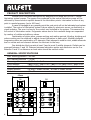
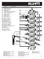
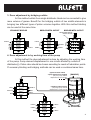
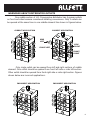
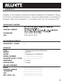
Centralized Lubrication Systems & Equipment PROGRESSIVE L.D. DISTRIBUTORS GREASE, LIQUID GREASE DISTRIBUTORS INTRODUCTION & USER MANUAL Pleace read before using the product YEARS WARRANTY THE PHYSICAL LIFE DETERMINED BY MINISTRY OF INDUSTRY AND TRADE OF TURKEY IS 10 YEARS. PRODUCT DESCRIPTION Modular pilot controlled distributors are designed to be used with ALLFETT central lubrication system pumps. The grease flow produced by the central lubrication pump will be delivered by these valves in specific doses to the lubrication points. Lubrication is done at any point in needed pressure (up to 400 bars). In case of blockage at any greasing point the next point will not be lubricated and system is stalled. The control of lubrication system is done either by electronic sensor on distributor or visual indicator. The error is show by the control card included in the system. This assures the full control of lubrication works. Progressive valves due to their modular design are separated by number of outlets and delivery values. Combination of piston sizes, pumps working and waiting periods, blinding, bridging and pulse counting are the methods to adjust correct lubrication to each point. Modular designed progressive valves are combination of 3 elements. Start element is used for inlet, middle elements are for outlets and end element delivers the lubricant to the loop. One distributor block consist at least 3 and at most 9 middle elements. Outlets can be arranged between 2 and 18. Distance between lubrication points and distributor can be 5 m. Between 5 and 10 m distances a check-valve should be used at outlet. GENERAL SPECIFICATIONS Max. working pressure : Min. working pressure : : Grease type : Piston dosages Working temperature : Middle sections : : Outlet tubes 400 bar. 7,5 bar. NLGI 0 - 1 - 2 - 3 (Ø4)0.050cc / (Ø5)0.078cc / (Ø6)0.113cc /(Ø7)0.154cc / (Ø8)0.201cc -25°C +80°C at least 3 middle section / at most 9 middle section Ø6 - Ø8 60mm 1 98 3/6 distributor block 50 19.7 19.7 19.7 19.7 19.7 24 PRODUCT COMPONENTS AND OPTIONAL EQUIPMENTS 1. Assembly screws 2. Ø13x1,5 O-Ring 3. Bridge body 4. Bridge coupling (with outlet) 5. Bridge coupling (blind) 6. Bridge washer 7. Blinding screw 8. Piston screw 9. Ø14x1,5 O-Ring 10. Ø3x1,5 O-Ring 11. Straight coupling 12. Sensore body 13. Sensore coupling 14. Ø3xØ7x3 nutring 15. Indicator coupling 16. Indicator piston 17. Indicator coupling screw 18. Sensore 19. End element 20. Start element 21. Ø8x1,5 O-Ring 1 20 2 21 3 22 23 4 5 6 24 25 7 26 8 27 9 10 28 29 11 12 13 30 31 14 32 15 33 16 17 18 19 22. Middle section 0.050cc 23. Piston Ø4 24. Middle section 0.078cc 25. Piston Ø5 26. Middle section 0.113cc 27. 28. 29. 30. 31. Piston Ø6 Middle section 0.154cc Piston Ø7 Middle section 0.201cc Piston Ø8 32. Ø4 Steel ball 33. M5 Setscrew 2 DISTRIBUTORS DOSE ADJUSTMENT METHODOLOGY 1. Dose adjustment by piston diameters There are 3 different type of pistons and their diameters are Ø4mm (0.050cc), Ø5mm (0.078cc) and Ø6mm (0.113cc). (These volumes are showing only one stroke in a cycle). If wanted volume of lubrication point matches to any piston size these middle elements should be used in the distributor block. 0.113 cc 0.078 cc 0.050 cc ALLFETT 0.113cc ALLFETT 0.078cc ALLFETT 0.113 cc 0.113 cc 0.078 cc 0.113 cc 0.050 cc 0.113 cc 0.050cc ALLFETT 0.113cc ALLFETT 0.113cc ALLFETT 0.113 cc 0.113 cc 0.113 cc 0.113cc 2. Dose adjustment by blinding outlets When piston dosages dont match with lubrication points volume needs blinding method can be used to get more volume for each outlet. If one outlet blinded in middle element opposite outlet in same middle element gives 2 times more volume of grease. In blinding method distributor blocks outlet quantity will be reduced by blinded outlets. As shown on the figure below 3/6 progressive distributors 3 outlets are blinded and 3 outlets are remaining. Ø2,5 Steel ball and M4 setscrew ALLFETT Blind 0.156 cc 0.113cc ALLFETT 0.078cc ALLFETT Blind 0.050cc 0.226 cc Blind 0.100 cc Blind 0.050cc Blind 0.226 cc 0.050cc 0.100 cc !! WARNING !! Setscrew and steel ball must be removed from the blinded 3 hole. If blinding will be removed, setscrew and steel ball must be replaced back to the hole. 3. Dose adjustment by bridging outlets In this method outlets from single distributor block can be connected to give more volume of grease. Benefit for the bridging outlets of two middle elements is bringing two different types of piston volumes together. With this method blinding can be used at the same time. STANDART BRIDGE BRIDGE WITH OUTLET BRIDGE WITH OUTLET Steel ball and setscrew must be removed ALLFETT 0.113cc 0.078cc ALLFETT 0.050cc 0.113cc ALLFETT Blind 0.113cc ALLFETT 0.178 cc 0.269cc 0.078cc ALLFETT 0.050cc Blind ALLFETT 0.304 cc 0.050cc 0.050cc 4. Dose adjustment to by working time of the pump In this method the dose adjustment is done by adjusting the working time of the pump. Pump element displacement in one minute divided by outlets of distributor(s). Piston rates should be chosen according to needs of lubrication points. If necessary blinding and bridging methods can be used or combined same time. (Optional outlet volume 2 pump elements are bridged) (Ø6) Two pump element displacement is 5cm³/minute (Standard outlet volume) ALLFETT Blind 0.641 cc 0.113cc ALLFETT 0.078cc ALLFETT Blind (SAMPLE) 0.928 cc (Ø6) Single pump element displacement is 2.5cm³/minute Blind 0.928 cc 0.113cc ALLFETT 0.154 cc 0.308 cc 0.050cc ALLFETT 0.154 cc Blind 24 V DC PUMP 0.050cc ALLFETT Blind 0.050cc 0.308 cc 4 DOSAGE ADJUSTMENT SCHEMAS ( x represent dosage ) 3/6 Block (5 outlets) 3/6 Block (4 outlets) x x 2x x x x x x x x x x 2x 2x 3/6 Block (3 outlets) Blind x Blind 3/6 Block (3 outlets) x x 2x Blind 2x Blind x Bridge 3/6 Block (4 outlets) Blind 2x Blind Blind 2x 2x Blind 2x Blind 3x 3/6 Block (2 outlets) 3x Bridge 5 Bridge STEEL SETSCREW BALL 3x !!! WARNING !!! Steel ball and setscrew, where inside piston hole, must be removed from the holes which will be blinding. When blinding is removed, steel ball end setscrew must be replaced again their position as before. WARNINGS ABOUT DISTRIBUTOR OUTLETS One middle section of L.D. Preogressive distributor has 4 grease outlets on front and sides because considered installing convenience. Only 2 outlets can be opened at the same time in one middle element like shown in figures below. CORRECT APPLICATION CORRECT APPLICATION LEFT RIGHT SIDE LEFT SIDE RIGHT FRONT LEFT FRONT RIGHT Only single outlet can be opened from left and right sections of middle element. One outlet should be opened from front left side or side left section. Other outlet should be opened from front right side or side right section. Figures shown below are incorrect applications. INCORRECT APPLICATION INCORRECT APPLICATION 6 RULES TO COMPLY WHILE USING AND WARRANTY CONDITIONS 1. Damages occur while additional transports after delivering the goods from ALLFETT to the customer, ARE NOT COVERED UNDER WARRANTY SCOPE. 2. Progressive distributors have pilot controled and modular build, one distributor block consist at least 3 and at most 9 middle elements. 3. If blinding will be done the setscrew and steel ball have to be removed in the hole blinding is done. If blinding will be removed the steel ball and setscrew have to be replaced back into its place. 4. Washing the distributor with pressurized water may couse defects. Damages occur from this reason ARE NOT COVERED UNDER WARRANTY SCOPE. 5. Use NLGI 0 for cold weather and increase the NLGI class up to 3 towards hot weather. 6. Grease will be used in the system must certainly be clean and any foreign material must not enter while filling. 7. Pump in the system must be filled in clean environment to avoid any dust or particules entering to reservoir. Damages coming from the small particules inside the system ARE NOT COVERED UNDER WARRANTY SCOPE. 8. Disassembly or loosen any part of the distributor while system is working is not allowed. Damages on pump and on the system coming from those reason ARE NOT COVERED UNDER WARRANTY SCOPE. 9. Progressive distributors must be assembled onto flat surface. If mounted on non flat surface gap will be come between middle elements and couses leakage on distributor. If you must assemble distributors onto non flat surfaces, distributor brackets must be used. 10. One distributor block consist at least 3 and at most 9 middle elements. Outlets can be arranged between 2 and 18. Distance between lubrication points and distributor can be 5 m. Between 5 and 10 m distances a check-valve should be used at outlet. 11. There must not be particule inside the lubricant used with progressive distributors. Because of this grease types with graphite couses harm to the system and must not be used. Damages coming from the small particules inside the system ARE NOT 7 COVERED UNDER WARRANTY SCOPE. RULES TO COMPLY WHILE USING AND WARRANTY CONDITIONS 12 Another goal of Centralized Lubrication Systems is to protect environment. So it is advised to fill grease to the systems by mobile or hand pumps. 13 Damages occur while fixing the pump by unauthorized staff ARE NOT COVERED UNDER WARRANTY SCOPE.Except the conditions mentioned in PUMP MAINTENANCE INSTRUCTIONS consult the technical service or leave the maintenance to technical service. 14 DANGEROUS OR HARMFUL CONDITIONS TO ENVIRONMENTAL AND HUMAN HEALTH DURING USE All ALLFETT systems are producing according to relevant provisions of security regulations. There is no risk for environmental and human health during use. PACKING & TRANSPORTATION All ALLFETT systems are packed with support material to reduce any harm to your mechanic and electronic equipment. But the packages must caried carefully by considering a posibility of a damage. 8 DISTRIBUTOR MAINTENANCE INSTRUCTIONS HOW TO DIAGNOSE BLOCKED GREASE POINT Make sure that the pump is working and the agitator is turning in the reservoir. Disconnect the high pressure hose which connected to pump element and run the pump. Please check if grease coming to outlet, if yes ; Disconnect the distributors inlet hose and send lubricant to distributor by hand pump. If pumping by hand pump is hard, or even not possible ; Remove one outlet from distributor then try send lubricant to distributor by handpump again. If pumping by hand pump still hard or not possible, remove next one outlet from distributor then try send lubricant to distributor by hand pump again. Try this step for every outlet of distributor. If pumping by hand pump to distributor is still hard even all outles are disconnected, that means distributor block is locked. Distributor should be disassembled carefully and all parts must be cleaned by diesel based liquid for correcting blockage. !!! WARNING !!! The most important point for disassembling the distributor is that the parts must be placed exactly the same as before. Even piston diameters are the same pistons must be inserted back to the same middle element they are taken from. If pumping by hand pump to distributor is easy, that means last lubrication point disconnected is locked. After checking hose condition the lockage on lubrication point must be corrected. If there is no grease coming from the pump element, please refer the pumps manual. To find locked lubrication points, all progressive distributors in the same sistem must be checked as written above. If problem still goes on even steps done written above, please contact with closest ALLFETT service. SERVICE STATION Telephone : +90 212 501 32 01 (PBX) 9 Fax : +90 212 501 33 37 www.allfett.net [email protected] WARRANTY Utilisation of this warranty certificate has been permitted by The Republic of Turkey, The Ministry of Industrial and Commerce, The general Administration of Protection of Consumer Right and Competition, in accordance with the law numbered 4077 . PRODUCER COMPANY NAME : CENTRAL ADRESS : TELEPHONE FAX : +90 212 501 32 01 (PBX) : +90 212 501 33 37 AUTHORISED PERSON SIGNATURE - STAMP : PRODUCT TYPE BRAND MODEL SERIAL NUMBER DELIVERY DATE / PLACE WARRANTY REPAIR TIME : : : : : : : Grease, liquid grease distributors ALLFETT Progressive L.D. distributor SELLER COMPANY NAME CENTRAL ADRESS TELEPHONE FAX BILL DATE / No. : : : : : ................................... ................................... ................................... ................................... ................................... ................................... ................................... 2 Years 30 days 10 WARRANTY CONDITIONS 1. The warranty period is two years from the date of delivery. 2. The product including all its components is under the warranty of our company. 3. In case of defects within the warranty period the period spent in repairing is added to the warranty period. The repairing period is maximum 30 days. This period starts from the date of delivery of the product to the services centers or to the seller, the agency the representative, the importer or the manufacturer of the product respectively, in case there are service centers. 4. In case the product has material, workmanship or manufacturing defects, the product will be repaired free of charge and expenses of any sort including labor, the value of the parts replaced or any our charges. 5. The product will be replaced free of charge; - If the product permanently disfunctions due to repeating the same defect more than four times within the warranty period - If the maximum period for repairing is exceeded. - If it is determined that the defect cannot be repaired by report written by the service, or in the absence of service centers, by the seller, agency, representative, importer or manufacturer of the product respectively. 6. The present warranty does not cover damages resulting from importer handling by deviating from the instructions in the manual. 7. General administration of protection of consumer rights and competition in the ministry of industry and commorce may be applied for problems concerning the warranty certificate.