1
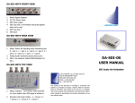
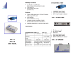
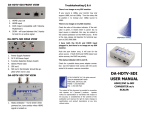
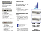
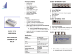
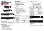
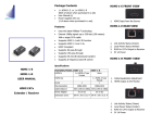
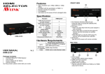
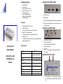
Package Contents DA-HDTV-SDI FRONT VIEW DA-HDTV-SDI User Manual Power Supply (5V 3.2A) Stereo Phone Jack (1 x 2) 75 Ω Terminator Power Supply Fastener Magnetic Mounting Plate Mounting Screws 1. HDMI Loop out 2. HDMI input 3. RJ45 Input (compatible with Tahoma Multiviwers) Features DA-HDTV-SDI Supports HDMI 1.2 and 1.3a 4. SCAN - will scan between the 2 inputs to look for an active signal HDCP Compliant DA-HDTV-SDI REAR VIEW Can convert 1080p input to 1080i output Built-in Color Bar generator Tahoma multiviewer compatible RJ45 input HDMI loop out 2 HD-SDI output with 4 channels of embedded audio Analog Stereo output Specifications USER MANUAL MODEL DA-HDTV-SDI DESCRIPTION HDMI to SDI Converter with Looping Input and Dual Output 1 x HDMI, 1 x RJ45 (HDMI) HDMI/DVI to SDI CONVERTER w/o SCALER INPUT 1. 2. 3. 4. 5. 6. Power Supply Fastener 5V 3.2A Power Input Function Selection Rotary Switch Stereo Phone Jack SDI out 1 SDI out 2 (Terminator should be applied when not in use) DA-HDTV-SDI TOP VIEW OUTPUT 2 x SDI, 1 Stereo Audio Phone Jack ADJUSTMENTS Rotary dial for interlacing and internal color bars MAXIMUM RESOLUTION / DIS- HD-SDI up to 140 m, 3G up TANCE to 120 m MOUNT Magnetic POWER 5V 3.2A DIMENSION 62 W x 112 D x 35 H (mm) 1. Status Indicator - Turns Green when powered on, turns amber when HDMI signal is locked on Installation Q: There is no image on my SDI monitor Connect the power supply and, if needed, lock the 5 VDC power jack with the supplied accessories (There is a small transparent plastic bag containing the PS holder and screws (x2) as well as two other screws for mounting the metal base). Connect a HDMI signal to one or the other input of the DA-HDTV-SDI. Connect the SDI output to the receiving device via a coax cable Use the internal test signals to ensure the proper connectivity in between the DA-HDTV-SDI and the receiving device. Select the test signal video format that will be in use when converting HDMI to SDI to validate that the receiving device accepts it. (E.g. keep in mind that if you feed a 1080p HDMI signal, the SDI output will be, by default, a 3G SDI signal) Trouble Shooting Q&A Accessories Now set the rotary switch to position 0 (default) or 1 if you feed a 1080p HDMI signal and want to get a 1080i SDI output signal to enable the conversion. The table below shows the supported formats. FORMAT 1920x1080p 60Hz 1920x1080p 59.94Hz 1920x1080p 50Hz 1080p60 1080p59.94 1080p50 1080i59.94* 1080p50 1080i50* 1920x1080i 50Hz 1080i50 1080i50 1280x720p 60Hz 720p60 720p60 720p59.94 720p59.94 1440x480i 59.94Hz 1440x576i 50Hz 720p50 720p50 480i59.94 480i59.94 576i50 576i50 *When rotary switch set to position 1 Check the color of the status indicator, if it is green, it means there is power, but no input source is detected. This maybe related to the content protection on the HDMI source. Please call contact Apantac for support Q: I have both the RJ-45 and HDMI input plugged in, but there is no image on my SDI monitor. Power Adapter Fastener 75 Ω Terminator Mounting Screws A: Push the scan button once, it will scan for the active source. If both RJ45 and HDMI inputs have active sources, the RJ45 has priority. Q: The status indicator LED is not lit. HDMI Pinout A: Check the power supply connection. It maybe loose. Please use the fastener that comes with the accessories kit to security the power adapter to prevent this from happening 1080p59.94 1080i59.94 1280x720p 50Hz A: 1080i60* 1080i59.94 1280x720p 59.94Hz Stereo Phone Jack (1 x 2) Power Adapter 1080p60 1080i60 1920x1080i 59.94Hz If your source is 1080p, your monitor may only support 1080i, but not 1080p. Turn the rotary dial to position 1 to change your 1080p source to 1080i Q: There is no image on my SDI monitor HDMI INPUT SDI OUTPUT 1080i60 1920x1080i 60Hz A: Pin # Signal Pin # Signal 1 TMDS Data 2+ 11 TMDS Clock Shield 2 TMDS Data 2 Shield 12 TMDS Clock - 3 TMDS Data 2- 13 CEC Reserved 4 TMDS Data 1+ 14 (N.C. on device) 5 TMDS Data 1 Shield 15 SCL 6 7 TMDS Data 1TMDS Data 0+ 16 17 SDA DDC/CEC Ground 8 9 10 TMDS Data 0 Shield TMDS Data 0TMDS Clock+ 18 19 +5 Power Hot Plug Detect © 2012 APANTAC LLC, All rights reserved 7556 SW BRIDGEPORT ROAD PORTLAND, OR 97224, USA PHONE +1 503 968 3000, FAX +1 503 389 7921 The content of this document are provided in connection with Apantac LLC (“Apantac”) products. Apantac makes no representation or warranties with respect to the accuracy or completeness of the contents of this publication and reserves the right to make changes to specifications and product descriptions at any time without notice