1
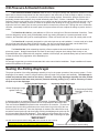
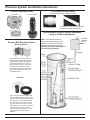
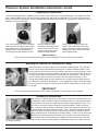
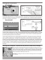
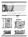
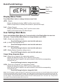
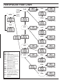
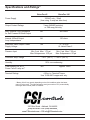
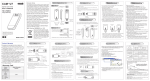
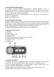
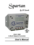
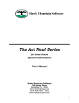
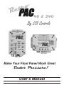
48 & 240
By CSI Controls
CSRP-240
CSRP-48
Make Your Float Panel Work Great
Under Pressure!
User’s Manual
CSI Pressure Activated Controllers
CSI’s Pressure Activated Controllers allow the user to change all settings and adjustments outside of confined
space with no electrical components from the control system in wet areas with no cords to tangle or adjust, no mercury,
no mechanical switches to fail, no probes to corrode, and no venting required. Because the pressure systems use a
proprietary pressure bell to operate, they exceed intrinsically safe Class 1, Division 1 standards. The pressure bell
transmits a pressure only signal to the controller so no voltage from the level sensing device enters the wet well. As the
water level rises in the basin, pressure is created in the pressure bell sending an air only signal to the controller. The
higher the level in the basin gets, the more pressure that is created in the pressure bell. Through the use of a RetroPac
controller, conveniently located in the control panel, this system allows the user to adjust all settings to precise levels, in
inches.
The RetroPac 48 & 240 are great additions to CSI’s ever evolving line of Pressure Activated Controllers. These
units are designed to quickly, easily, and affordably retrofit any existing float panel to a pressure activated control.
However, the RetroPacs aren’t just for retrofit applications. Either unit can be built into a new CSI control panel as well.
The RetroPac 48 is especially designed for quick and simple set-up and installation. It comes ready to be wired
into your float panel with wire leads 24 inches in length. Just wire into the existing float leads, set the dials to the
desired setpoints, and install the pressure bell. Retrofitting a system could not be easier!
The RetroPac 240, while maintaining simplicity, offers exceptional value and flexibility to meet the needs of
almost any system. Straight forward liquid level read out and easy to program level settings make it easy to use.
Expanded depth range, differential relay setpoints, scalable 4-20mA output, and optional battery back-up make it flexible
to meet the needs of any application at an affordable price.
Important:
We strongly suggest that you read and understand this entire manual before installation. Proper installation will ensure
trouble free operation of the system.
Seating the Rolling Diaphragm
The proper operation of the rolling diaphragm assembly is key for the proper operation of the pressure system. For the
diaphragm to be seated, it must be snug around the push-cup inside of the pressure bell assembly. The diaphragm is
seated and protected when sent from the factory. However, if the rolling diaphragm assembly has been pushed
up by some method other than water pressure (someone manually pushing on it), it will be necessary to reseat
the push cup in the diaphragm.
Properly Seated Diaphragm
Improperly Seated Diaphragm
Rubber Diaphragm is tight
against Push Cup
Air Gap between Rubber
Diaphragm & Push Cup
A diaphragm that is not seated properly must be reseated. Reseating the diaphragm can
be accomplished by plunging the pressure bell into a liquid depth of about three feet.
This must be done without the pressure tube connected to the controller. (To remove a
pressure tube from the fitting push down on the small center ring on the top of the connector and pull the tube out). Once the diaphragm is reseated, the rubber will be snug
around the internal push-cup and when lightly touching the diaphragm the push-cup can
be felt immediately behind the diaphragm. Then make sure the pressure tube is reconnected to both the pressure bell and the controller before the bell is submerged in liquid.
*IMPORTANT*
The tube must be pushed into the fittings 5/8” or the unit will not work correctly!
Note: Pressure Bells manufactured after 07/01/2008 contain a brass
barbed fitting instead of the plastic push-in fitting pictured here.
Push here and pull tubing to remove tubing
Pressure System Installation Instructions
Standard Systems Include:
Controller
Pressure Bell
50ft of Tubing
The Installer Will Also Need:
(For Mounting Bracket Installation ONLY)
A 2” Male Adaptor
A length of 2” PVC pipe long enough
to reach the bottom of the basin
Typical Simplex Pressure System Installation
Using a CSI Mounting Bracket
Pressure Bell Mounting Options
Mounting Bracket
When using the mounting bracket to
install the pressure bell, start by placing the bracket against the tank wall
and mark the holes for the anchors.
Drill the holes in the side of the tank
and fasten the bracket to the tank.
The bracket should be mounted near
the top of the tank with access from
the manhole cover.
Tether Kit
When using the tether kit simply slide
the 8 lb donut over the top to the pressure bell and thread the nipple into the
pressure bell. Then suspend the bell
by securing one end of the provided
poly rope to the bolt on the top of the
nipple and secure the other end of the
rope near the top of the basin with
access from the manhole cover. Top
mount eyebolt is provided by the
installer.
Note: Care should be taken to
insure that sewage gases are not
allowed to enter the control panel
with an approved sealing means!
(Damage caused by sewage gas is
not covered by warranty).
RetroPac
mounted
inside
panel
Pressure System Installation Instructions Contd
Preparing the Pressure Bell
Once the mounting bracket is installed, you will need to cut the PVC pipe to the desired length. The length of the PVC
pipe = Depth of Basin minus 14 inches (for the pressure bell) and minus an additional 6 to 12 inches (so the pressure
bell is off the bottom of the basin). Once the length has been determined and the PVC has been cut attach the 2” male
adaptor to one end of the pipe.
If for some reason your factory installed
tube has been removed you will need to
firmly attach the 1/4” poly tubing to the
fitting at the top of the pressure bell.
The tubing must push in 5/8 of an inch
With the tubing securely
attached to the pressure bell,
feed it through the PVC pipe
from the side with the male
adaptor already attached.
Finally, with the tubing securely fastened to the pressure bell and all the
tubing fed through the pipe, thread the
adaptor to the top of the pressure bell
(Hand Tighten Only!).
*IMPORTANT!
The air tube must be pushed into the quick connect fitting 5/8” or the unit will not work correctly!
Mounting the Controller & Connecting the Tubing
First, determine a mounting location for the controller inside the panel. The controller
can be mounted using the attached mounting feet or another available method. Next,
run the pressure tube from the top of the pressure bell into the control panel (we recommend using a conduit). With the controller mounted in a convenient location in the control panel, attach the other end of the 1/4” poly tubing to the controller. To help insure
that your system does not leak air it is best to not cut or splice the tubing. Leave
enough extra tubing coiled up at the pressure bell mounting bracket to allow the pressure bell to be removed for maintenance. If your installation requires cutting the tubing
to exit a junction box make sure that you use the MPCF coupler fitting to insure a proper air seal!
*IMPORTANT*
The air tube must be pushed into the quick connect fitting 5/8” or the unit will not work correctly!
Installing the Pressure Bell
With all the 1/4” tubing connected, you will need to remove the “Do Not Push or Pull
the Diaphram” sticker from the bottom of the pressure bell. Do not push the bottom
of the pressure bell, but feel to make sure the rubber is tight against the cup. If it is
not, refer to the section entitled “Seating the Rolling Diaphram” before continuing.
Also, make sure that all tubing is connected between the pressure bell and the control panel before submersing the bell in liquid. Note: Should the tubing become disconnected while the pressure bell is in the liquid you will need to pump the station
down manually before reconnecting the pressure tubing. If there is an air leak or the
diaphram is not seated properly the system will not give an accurate measurement.
The pressure bell can be mounted at any height off of the bottom of the basin that
you desire. Remember that the lowest you will be able to measure will be at the bottom surface of the large union nut
on the pressure bell.
Wiring the Controllers
RetroPac48
The RetroPac Controller requires 115VAC power only. Simply connect the white neutral wire (N) to 115VAC neutral connection and the blue power wire (L) to 115VAC hot connection. The outputs are normally open dry contacts and they will
close when the liquid level exceeds the level set point of the corresponding output. Connect the outputs as required to
your system. An example is shown above.
RetroPac240
The RetroPac240 controller has two terminal strips. The ten pole terminal strip is for the power and output contacts.
From left to right the terminals are as follows. The first two terminals are the power to the RP240 controller. The RP240
controller requires 120VAC power only. Simply wire the neutral wire into the N terminal and line voltage into the L terminal. The rest of the terminals are output contacts, labeled R1 thru R4. These contacts are completely programmable,
see RP240 programming section for more information.
The three pole, terminal strip is for the 4-20mA output built into the RP240. This output can be used to indicate liquid
level to a Variable Frequency Drive, a Programmable Logic Controller, or other industrial control equipment. If necessary, connect the 4-20mA loop next. This output is not isolated from the rest of the control circuitry inside the RP240
controller. This output is isolated from all of the power connections on the ten pole terminal strip. This 4-20mA loop can
be self powered or powered by an external power supply, as shown above. The internally powered 4-20mA loop is limited to a maximum of 400 ohms loop resistance. If an external power supply is used the power supply should be UL listed class 2, 9-30VDC. A twisted, shielded wire pair should carry the 4-20mA signal, with the shield connected to earth
ground at one point only. The 4-20mA loop is completely programmable, see RP240 programming section for more
information.
Setting the Outputs - RetroPac 48
(RP240 is Under RP240 Settings)
With all the tubing connected and the pressure bell installed in the basin you are now
ready to adjust your level settings. To adjust the float settings turn the dials to the desired
depth in inches on the faceplate. The inches on the dials are measured from the bottom
of the union nut surface on the pressure bell upward. For example, if your Output #1 is
wired into the Lead Float position then just turn the Output #1 dial to the level in inches
that you would like the Lead Pump to come on at.
Remember: All settings are relative to the bottom of the large union nut on the pressure
bell in the basin.
Fine Adjustments - RetroPac 48
With the pressure units the settings can be adjusted to a
precise measurement. Using a digital volt meter, set on
DC-Volt setting and placing the negative lead to the screw
labeled “CAL” on the lower left corner of the front of the
enclosure and the positive lead to the metal strip on the
side of the dials, the volt meter will give a reading in inches by moving the decimal to the right one number. So a
reading of 1.514 is the equivalent of 15.14 inches.
Check installation by turning power on and manually running up the water level to test for proper installation. Test
the unit periodically to ensure proper operation.
That’s how easy it is to install the RetroPac Systems from CSI Controls. If you need any additional help please cotact
your local CSI distributor or call the factory for technical assistance.
1-800-363-5842
Enclosure
A: 5.25”
B: 3.00”
C: 1.45”
Dimensions
Mounting Holes
D: 4.75”
D
D
A
B
A
B
C
C
RetroPac240 Settings
dEPH
Menu/Enter
Button
Set/Change
Button
Display Menu Fields
Press Menu/Enter button to change between menu fields.
dEPH - (Depth)
Display will alternate showing “dEPH” and the current value.
Reads out liquid level in inches(0-240 inches for pressure bell input)
OutC - (Output Current)
Display will alternate showing “OutC” and the current value.
Reads out the actual value of 4-20mA Output
User Settings Main Menu
Press and hold Menu/Enter Button for 3 seconds while in the Display Menu to enter into
this menu. Press the Menu/Enter Button to change between menu fields.
OutS - (Output relay setpoints menu):
Press Set/Change button to enter into this sub-menu.
4-20 - (4-20mA output settings menu):
Press Set/Change button to enter into this sub-menu.
InSc - (Input Scaling menu):
Press Set/Change button to enter into this sub-menu.
btOP - (Battery Backup Operation settings menu):
Press Set/Change button to enter into this sub-menu.
Output Relay Setpoints Menu
On # - (Relay turn on setpoint, # is output relay number)
Display will alternate showing “On #” and the current value.
When the level input is equal to the value entered in this field the corresponding
relay will turn on.
Press Set/Change button to change this field.
OFF# - (Relay turn off setpoint, # is output relay number)
Display will alternate showing “OFF#” and the current value.
When the level input is equal to the value entered in this field the corresponding
relay will turn off.
Press Set/Change button to change this field.
Note: If the ON setpoint is higher than the OFF setpoint then the liquid level gets up to the ON setting and turns back off
when the level gets back down to the OFF setting. If the ON setpoint is lower than the OFF setpoint then the relay will
turn on when the liquid level gets down to or below the ON setpoint and will turn back off when the level gets back up to
the OFF setpoint. The ON and OFF setpoints must be at least 2 inches apart (Ex: OFF = 58, ON = 60). If they are not
the program will automatically adjust them so they are.
4-20mA Ouput Settings Menu
4 SP - (4mA output setpoint)
Display will alternate showing “4 SP” and the current value.
When the tank level is equal to this level the mA output will be = to 4mA.
Press Set/Change button to change this field.
20SP - (20mA output setpoint)
Display will alternate showing “20SP” and the current value.
When the tank level is equal to this level the mA output will be = to 20mA.
Press Set/Change button to change this field.
Note: The 4mA setpoint and the 20mA setpoint can be any value. Similar to the ON and OFF setpoints, the 4mA could
be set lower or higher than the 20mA setpoint. If set lower, the 4-20mA output would start at 4mA when the depth level
was low and as the level increased, the 4-20mA output would increase. If set higher, the 4-20mA output would start at
20mA when the depth level was low and as the level increased, the 4-20mA output would decrease. Also, the user
should be aware that the 4mA and 20mA setpoints can be set outside the measurable range of the unit. For example, if
the Input Offset value is set to 12 inches, the 4mA value can still be set to 0 inches, even though the system won’t be
able to measure anything below 12 inches. The 4-20mA output value, in this case, would never be able to reach the
4mA value.
Input Scaling Menu
InOS - (Input Off Set)
Display will alternate showing “InOS” and the current value.
The value entered into this field will be added to all measurements made by the
pressure bell. This way, the depth display can show the liquid level from the bottom of
the tank, or any other desired reference point. This offset will be taken into account by
all other setpoints. (Maximum setting is 699)
Press Set/Change button to change this field.
Battery Backup Operation Settings Menu
PFr# - (Relay On/Off during powerfail, # is output relay number):
Display will alternate showing “PFr#” and the current value.
Press Set/Change button to change this field.
Possible Settings:
1 = (Default Setting) The relay will continue normal operation during power failure
(if battery backup pack is plugged into it)
0 = To conserve battery power the relay will turn off during a power failure.
PFOc - (4-20mA output current loop On/Off during powerfail):
Display will alternate showing “PFOc” and the current value.
Press Set/Change button to change this field.
Possible Settings:
1 = (Default Setting) the 4-20mA current loop will continue normal operation during a
power failure (if a battery backup pack is plugged into it)
0 = To conserve battery power the 4-20mA current loop will turn off during a power failure
PFAr - (Power Failure Alarm Relay Selection)
Display will alternate showing “PFAr” and the current value.
Press Set/Change button to change this field.
Possible Settings:
0 = No relays will indicate the power failure condition
1-4 = Selects which output relay will close to indicate a power failure condition.
Note: (Battery backup pack must be used for this feature to work).
RetroPac240 Flow Chart
dEPH
Press
& Hold
Menu/
Enter
Button
OutS
On#
To Change Field
OFF#
To Change Field
OutC
4-20
4 SP
To Change Field
20SP
To Change Field
InSc
InOS
To Change Field
Display Key
dEPH - Depth
OutC - Output Current
OutS - Output relay setpoints menu
4-20 - 4-20mA output settings menu
InSc - Input Scaling menu
btOP - Battery Backup Operation
settings menu
On # - Relay turn on setpoint, # is
output relay number
OFF# - Relay turn off setpoint, # is
output relay number
4 SP - 4mA output setpoint
20SP - 20mA output setpoint
InOS - Input Off Set
PFr# - Relay On/Off during powerfail,
# is output relay number
PFOc - 4-20mA output current loop
On/Off during powerfail
PFAr - Power Failure Alarm Relay
Selection
btOP
PFr#
To Change Field
PFOc
To Change Field
PFAr
To Change Field
Specifications and Ratings*
RetroPac 48
Power Supply
RetroPac 240
120VAC only - 35mA
(fuse using .5 amp fast blow fuse)
Output Contact Ratings
3 amp 240VAC(resistive)
or 2.88 amp pilot duty
Max. External Loop Resistance
for Self Powered 4-20mA Output
NA
400 ohms
Internal 4-20mA Output
Loop Independance
NA
150 ohms
External 4-20mA Output Power
Supply Voltage
NA
Pressure Input
9 - 30 VDC
UL Listed Class 2
Min: 0 psi Max: 1.73 psi
Max Overpressure: 10.8 psi
Controller Temp. Range
Min: 0 psi Max: 7.25 psi
Max Overpressure: 29 psi
- 40°F (-40°C) -- +185°F (+85°C)
Humidity
95% non-condensing
Fresh Battery Life on a
Power Fail w/1 relay on**
NA
Approx. 16hrs
Terminal Ratings
4.5 lbs.-in. Terminal Torque
Use 12-28 AWG copper wire only
*Equipment was evaluated at an ambient air temperature of 25°C
**Battery life will vary greatly depending on the field conditions when the batter
power is being used. The optional battery pack (part number: PP1) automatically
recharges when normal power is restored.
220 Ohio Street • Ashland, OH 44805
281-5767 • Fax (419) 289-2535
(419) 281-1940
www.CSIcontrols.com • [email protected]
www.chandlersystemsinc.com
• [email protected]