1
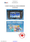
EK-FT-12 Chapter 1 Introduction of EK-FT-12 BMS 1.1 Product Structure With the distributed two-level management system, EK-FT-12 electric vehicle BMS (hereinafter called EK-FT-12 system) is composed of Battery cluster-management unit (BCU) and multiple Battery monitor unit (BMU), display screen (LCD), insulation detection module (LDM), heavy-current control system (HCS), current sensor (CS) and wiring harness. 图 1-1 产品结构 1.2 System Configuration Figure 1-2 System Configuration 1.3 Brief Introduction of Function In EK-FT-12 system, BCU module carries out real-time communications with multiple BMU modules and LDM (insulation detection module) through CAN bus to gain system parameters, such as single cell voltage, box temperature and insulation 1 User manual of EK-FT-12 BMS resistance and so on, collects charging and discharging current through current sensor, calculates SOC dynamically and displays related data through touch screen. BCU manages system after gaining comprehensive information of battery pack through calculation and analysis, respectively interacts with ECU, motor controller and charger and so on intelligently through independently CAN bus and can realize the secondary protection of charging and discharging through relay control to meet diversified safety control demands of customers, ensuring stable and effective operation of system. 1.4 Technical Specifications Type Voltage collection range Voltage collection accuracy Accuracy of total voltage Current collection accuracy Error of SOC estimation Temperature collection accuracy Temperature collection range Specification 0~5V ≤±5mV ≤0.2% ≤±1% 500A current sensor ≤5% ≤±1 ℃ -30~75℃ -40~125℃ ≥1A(normal temperature) Balance current Power consumption of BMU operation Power consumption of BCU operation Working input voltage System operating temperature Storage temperature Weight Charging control mode Discharging mode Remarks control ≤1W 2 channels of balance can be switched on at the same time One BMU module,均衡不开启 ≤2.8W DC 12/24V -30~75℃ -40~85℃ BCU:480±5g BMU:640±5g One module CAN communication, Depend on actual conditions active/passive output CAN communication, Depend on actual conditions active/passive output 1.5 Battery cluster-management unit (BCU) BCU function SOC estimation: use Joint EKF algorithm to estimate SOC of battery pack dynamically Current detection: carry out real-time detection of current in charging and discharging circuits through Hall current sensor. Communication function: externally installed 3 CAN interfaces, which can be used to communicate with BMU, complete vehicle controller and charger and so on to exchange voltage, temperature, fault code, control command and other information. Alarm and protection: when there is fault as over-charge, over-discharge and so on, BCU can perform the corresponding alarm and protection according to fault status and display it on LCD screen. 2 User manual of EK-FT-12 BMS System expanding: BCU supports multiple channels of active/passive node output and can realize two-level control management through CAN communication and relay to ensure effective isolation of strong and weak current and meet diversified safety control demands of customers. Data storage: support 8G data storage capacity and can record all performance parameters of long-term operation System self-check: the system checks itself and BMU working status after power on to ensure normal working of of power battery pack and dispatching and fault events of battery module. system. Remote management: BCU is equipped with wireless communication interface, which can realize four-remote function through external DTU module. System upgrade: program downloading interface is installed externally, which can be used to upgrade system within 30 seconds. Parameters of BCU module Item Performance Working DC 12V/24V voltage Current detection range±500A(Optional) Current detection ≤±1% accuracy Error of SOC ≤5% estimation Total voltage, total current, maximum and minimum voltages and serial numbers, voltage of single battery, box temperature, charging and discharging status, over-charge alarm Display prompt, under-charge alarm prompt, over-discharge alarm prompt, over-temperature alarm prompt and insulativity alarm prompt, etc. Grade I alarm: prompted alarm information appears on display screen and no control measures are taken: Single cell voltage ≤3.0V; 100Ω/V≤ insulativity ≤500Ω/V Alarm Grade II alarm: prompted alarm information appears on display screen and there is bumming; disconnect charging and discharging circuits: Single cell voltage ≤2.5V or single cell voltage ≥3.9V; delay: 5-30S; Box temperature ≥75℃; Insulativity ≤100Ω/V Use CAN bus and relay to control: When the cell voltage of single battery ≥3.65V, carry out CAN communication with charger and the current value gradually decreases according to smooth curve. When the cell voltage of single battery ≥3.9V, disconnect charger output after 30S Charging delay. control mode When the cell voltage of single battery <3.4V, charger can be used again for continue charging. When the box temperature ≥75℃, charger is abnormal or charging circuit is disconnected. Use CAN and high-voltage relay to control: when cell voltage of single battery ≤3.0V, ,communicate with motor controller by CAN communication to reduce motor output power. Discharging When the cell voltage of single battery ≤2.5V, disconnect motor power output after 5~ control 10S delay. When single core voltage > 2.6 V festival, the motor controller can continue to output power. When battery box temperature ≥75℃, disconnect discharging circuit.。 Note: *all protection parameters in table can be configured. 3 User manual of EK-FT-12 BMS 1.6 Battery monitor unit (BMU) BMU function BMU connects with battery pack through voltage detection wire, collects voltage of 16 strings of battery cell at most and can equalize battery according to battery single cell voltage. When the voltage of some single cell battery in battery box reaches to 2.8V and battery voltage difference is between 10mv-800mv, the balance function will start automatically. Each battery detection unit can switch on 2 channels of balance at the same time at most. BMU collects box module temperature through 4 temperature sensors at most and can actively manage cooling and heating according to temperature status to ensure battery application capacity and prolong battery service life. The working power supply of BMU has to be provided by the external 12V (9V~18V self-adaption) or 24V (18V~36V self adaption) DC power source. BMU transmits the collected battery voltage, box temperature and other information to Battery cluster-management unit through CAN bus. Detection of single cell voltage: realize the real-time detection of each single cell voltage through isolated collection Temperature detection: put 1~4 temperature sensors in box of battery module to realize the real-time detection of of series single cell voltage. box temperature. CAN communication: transmit the voltage, box temperature and other information of each single cell in battery pack to BCU through CAN bus. Balance function: balance management can be performed to battery cell according to agreed balance management control strategy to improve the consistency of single battery cell and application performance of battery pack. Heat management: BMU can manage the cooling and heating status of battery actively according to battery box temperature to ensure battery application capacity and prolong battery service life. System upgrade: program downloading interface is installed externally, which can be used to upgrade system within 30 seconds. Parameters of BMU module Item Maximum quantity of collection string Working voltage Voltage collection range Collection accuracy of single cell voltage Temperature collection range Temperature detection accuracy Communication interface Voltage sampling period Cooling/heating current Parameter Remarks 16 strings DC9V~32V 0~5V ≤±5mV -40~125℃ ≤±1 ℃ -30~75℃ CAN 200ms 16S ≤1.2A Peak value 5A 4 User manual of EK-FT-12 BMS 1.7 Insulation Detection Module (LDM) LDM function LDM is used to detect whether the battery pack has electricity leakage on vehicle body. LDM receives the command from BCU through serial bus and transmits the detected data information to BCU, which then will deliver LDM status to display screen. Method to judge whether the battery leaks electricity onto vehicle body: respectively detect whether the insulativity between positive/negative pole of vehicle-mounted battery and body shell is more than 100Ω/V. Insulativity System Status Display Screen Insulativity≥100Ω/V Normal system display Total pressure testing System alarm I (No icon) Bus abnormal abnormalities Insulativity≤100Ω/V System alarm II Display insulation leakage (Red)system cuts off circuit. 1.8 Heavy-current Control System (HCS) Heavy-current control system includes heavy-current control module, charging and discharging control circuits and pre-charge circuit, etc. HCS function Charge and discharge control: charging/discharging of battery is controlled through switching on/off high-voltage relay to prevent over-charge and over-discharge of battery; besides, the function of relay contact detection is also equipped to prevent sticky point of relay in circuit. Pre-charge circuit: before switching on the discharging high-voltage relay of main circuit, it is necessary to switch on the pre-charge circuit firstly to charge capacitance. Then, switch on the high-voltage relay of main circuit when the voltage at both terminals of capacitance has reached to setting threshold value to ensure the reliability of high-voltage relay of main circuit. CAN and RS485 communication: use CAN or RS485 bus to communicate with BCU, upload relay status and other information and receive the control command from BCU. Table of Relay Model Selection Item Relay Model Code Detailed Parameters 01 EV200AAANA 02 400V/10A 03 400V/80A 04 400V/120A 5 User manual of EK-FT-12 BMS Model Selection Table of Power and Resistance of Heavy-current Module Item Power Model Code Detailed Parameters 00 50W 01 75W 100W 02 04 300W 01 50Ω Resistance 02 Model 03 75Ω 100Ω 07 240Ω 1.9 Current Sensor (CS) CS function The current of this system is detected with Hall open-loop current sensor with optional range 50A~1000A. Model Selection Table of CS Item Code Detailed Parameters 01 50A 02 100A Current 04 200A Type 05 300A 07 500A 10 1000A 1.10 Display Screen (LCD) LDM function The display screen is human-machine interface for displaying system operation status. All its models are designed according to industrial standard and suitable for applying in various conditions. The display interface of LCD can display all operation parameters and faults of system. Status description of LCD The operation indicator of display screen includes three ones: power supply (PWR), running (RUN) and communication (COM). When the display screen is powered on, the power indicator (PWR) is normally on; if the running indicator (RUN) is normally on in yellow, it stands for normal running of display screen; if the running indicator (RUN) is not on, it means that the display screen has fault; when the display screen has connected with BMS, the communication indicator (COM) flashes in yellow. 6 User manual of EK-FT-12 BMS Figure 1-3 Running Status Indicator The following table shows the display status of three LED indicators under various conditions: Equipment Status Green LED (PWR) No power supply ○ ○ ● ● ● 3.5’’ screen Power on, no communication 5.7’’ screen ● ● Communicate with connected equipment ● ● ○ LED off Yellow LED (RUN) Yellow LED (COM) ○ ● LED on ○ ※ ※ Flash Display description of LCD The integrated interface information of display screen is as shown in the figure below: Display alarm information Display current Display SOC Display voltage Display temperature Figure 1-4 Figure of LCD Display Interface Model Selection Table of LCD Item Code Detailed Parameters 01 3.5’’ Display screen LCD Model 02 5.7’’ Display screen Chapter 2 Installation of System 2.1 Installation Dimension and Weight of Product Overall and Installation Dimensions (unit: mm) Weight Product Type BCU W H D W1 H1 165 106 43 100 50 7 D1 d (KG) M4 0.64 User manual of EK-FT-12 BMS BMU 124 91 40 100 40 M4 0.48 LDM 165 120.5 25 105.5 85 15 4.5 1.05 HCS 260 240 100 130 225 26 6 — 96 81 47 90 75 5 4 0.186 177 140 40 160.6 LCD 130.5 6 4 0.5 Note: W, H and D are dimensions of external structure; W1, H1 and D1 are installation dimensions of internal structure; d is width of mounting hole. 2.2 chematic Diagram of Overall Dimensions Battery cluster-management unit (BCU) 8 User manual of EK-FT-12 BMS 图 2-1 BCU Overall Dimension Battery monitor unit(BMU) 图 2-2 Insulation Detection Module(LDM) 图 2- BMU Dimension Dimension Display Screen(LCD) 9 User manual of EK-FT-12 BMS 图 2- Overall Dimension of 5.7’’ LCD Current Sensor(CS) Figure 2-5 CS Overall Dimension 10 User manual of EK-FT-12 BMS Heavy-current Control Box Figure 2-6 Overall Dimension of Heavy-current Control Box 2.3 Interface Description BCU interface Internal interface SD card Figure 2-7 Front Interface of BCU Communication and switching output interface 11 1 11 2 12 通 量 2 信 输 20 User manual of EK-FT-12 BMS Interface for communication 1 supply, output and input and switching output 19 Interface for system power Interface for weak voltage 电 检 Fig 2- Interface of BCU BMU interface Interface for relay,ower supply Interface for voltage detection Interface for temperature detection Figure 2-9 Front Interface of BMU 12 and CAN communication 压 及 出 LDM interface Positive pole(red) Negative pole(black) Figure 2-10 Front Interface of LDM -20- 13 User manual of EK-FT-12 BMS 14 RS485 communication interface RS485 communication interface Figure 2-11 Back Interface of LDM 5.7” LDC interface Figure 2-12 5.7'' LCD Interface CS interface 图 2-13 CS interface -21- 15 User manual of EK-FT-12 BMS 2.4 Wiring Diagram of System Figure 2-14 Schematic Diagram of Installation Note: * products of different models may have some difference in functions and settings. The installation method of -22- 16 User manual of EK-FT-12 BMS special connecting lines and adaptors will be provided by our company separately. 2.5 Wiring Description of BMU Connection of voltage detection wiring harness (take 16 strings for example) B1+ connects with positive pole (red line) of first battery; B1-~B15- connect with negative pole (black line) of each battery in series successively; B16- connects with negative pole (green line) of the last battery. Positive pole of battery module Negative pole of battery module Figure 2-15 Schematic Diagram of Connection between Voltage Detection Wiring Harness and Battery Figure 2-16 Example Diagram of Connection between Voltage Detection Wiring Harness and Battery Caution: the connection order of voltage detection wiring harness cannot be wrong. Otherwise, the voltage collection may be incorrect, equalizing circuit may be burnt out and battery may be damaged. Fix temperature sensor onto battery pack Figure 2-17 Example Diagram of Temperature Sensor Connection 17 User manual of EK-FT-12 BMS Connect voltage detection cable harness and temperature detection cable to BMU Figure 2-18 Example Diagram for Connection of Voltage Detection Cable Harness and Temperature Detection Cable Connection of CAN Communication Cable CAN communication cable is the communication medium between BMU and BCM. The system adopts 3-core shielding line to be communication cable. MOLEX12pin connector assembly and AMP 6PIN automobile connector (cellular type and pin type) are used for joint。 The BMU farthest away from BCU connects to No. 2 line and others connect to No. 1 line. Figure 2-19 Example Diagram for Connection of Communication cables among BMUs Connect the BCU power line, red line to connect power positive, black line across the connect power Figure 2-20 Example Diagram for Connection of BMU power line User manual of EK-FT-12 BMS 18 User manual of EK-FT-12 BMS 2.6 Wiring Description of BCU Connect communication cable s between BCU and BMU Figure 2-21 Diagram for Connection of Communication cable s between BCU and BMU Connect current sensor The current sensor is strung onto the circuit cable of output positive/negative pole of battery pack and has two kinds of wiring modes, as shown in the figure below (pay attention to the arrow on current sensor). Figure 2-22 Schematic Diagram for Connection of Current Sensor Installation Connection method 1 Connection method 2 19 User manual of EK-FT-12 BMS Figure 2-22 Example Diagram for Connection of Current Sensor Connect the control cable of charge/discharge relay (red line connects with positive pole of relay coil and black one with negative pole of relay coil). Figure 2-24 Example Diagram for Connection of Relay Control Cable Connect CAN communication cables of charger and complete vehicle system/motor controller. (For 3-core shielding line: red is H, yellow is L and black is GND) Figure 2-25 Example Diagram for Connection of CAN Communication Cable Caution: 1. Confirm that the connection of “H” and “L” of CAN bus is correct. Otherwise, CAN bus cannot communicate with other devices. 2. Confirm that the matched resistance of CAN bus is correct. Otherwise, CAN bus cannot communicate with other -26- 20 User manual of EK-FT-12 BMS devices. Connect the power supply cord of BCU (red line connects with positive pole of power supply and black one with negative pole). Figure 2- 26 Example Diagram for Connection of BCU Power Cord 2.7 Wiring Description of LDM Connect communication cables between LDM and BCU。 Figure 2-27 Example Diagram for Connection of Communication Cables between LDM and BCU Connect LDM to the master positive pole and master negative pole of battery pack; and make LDM shell contact with vehicle body and keep well conducting between them (LDM shell grounded). -27- 21 User manual of EK-FT-12 BMS Figure 2-27 Example Diagram for Connection of Communication Cables between LDM and battery positive and negative terminals Caution: LDM shell must well contact with vehicle body. Otherwise, functions of LDM will be invalid! Dangerous: it is necessary to wear insulation gloves when connecting positive/negative pole wire of detection. Otherwise, electric shock may be caused! 2.8 Wiring Description of LCD Wiring description of display screen Figure 2-29 Example Diagram for Connection of LCD and BCU(take 5.7’’ one for example) Caution: 1. the communication cable interface (DB9 connector) of LCD connects to COM1 communication interface of LCD. If it is connected to COM2 interface, the LCD communication will be interrupted! 2. The connection of positive and negative poles of LCD power cannot be reversed. Otherwise, LCD will be burnt out! 3. LCD is powered by DC24V. The positive pole connects with 24V+ and negative one with 24V-! 2.9 Installation Conditions and Requirements Avoid installing the system under the condition with oil mist, metallic dust and much dust. 22 User manual of EK-FT-12 BMS Avoid installing the system under the condition with harmful gas and fluid or corrosive, flammable and explosive gas. Reserve appropriate installation dimensions. Cable installation shall be kept away from sharp objects. Try best to keep away from conditions with strong electromagnetic interference. Parameters of all parts related to his system shall be confirmed by our company. 23 Chapter 3 Wiring of System 3.1 Type of Cable No. Name Specification Remarks 0.5 high temperature wire: one end is MOLEX28PIN connector Size of cold pressed terminal is assembly; determined according to the actual the other end is 1.5-8 cold pressed demand of customer. Voltage detection cable 1 terminal. 2×0.5 high temperature wire: Temperature one end is MOLEX28PIN connector detection cable assembly; the other end is temperature 2 sensor. Heating relay control line Refrigeration relay control line 2×0.5 power line: one end is MOLEX16PIN connector assembly; the other end is null. 2×0.5 power line: one end is MOLEX16PIN connector assembly; the other end is null. 2×0.5 power line: 3 one end is MOLEX16PIN connector BMU power line 1 Power supply into BMU assembly; the other end is3PINAMP pin-type connector assembly. Communication cable among modules 3×0.5 shielding line: one end is MOLEX16PIN connector assembly; the other end is AMP3PIN connector Communication among BMUs assembly (cellular type and pin type). 6×1.0 high temperature wire +2×0.5 AMP cellular connector assembly. is equal power line to the number of BMU quantity. Main line 4 BMU power line 2 one end is 30A connection assembly; connect with several AMP2PIN cellular the other end is AMP2PIN cellular connector. connector assembly. 2×0.5 power line: 5 Power line one end is MOLEX12PIN connector assembly; the other end is null. 24 2×0.5 power line: one end is MOLEX12PIN connector assembly; Discharge relay cable the other end is null. 2×0.5 power line: one end is MOLEX12PIN connector assembly; Input signal cable the other end is null. 3*0.5 shielding line: one end is MOLEX20PIN connector assembly; CAN cable of whole car Charge CAN cable the other end is null. 3*0.5 shielding line: one end is MOLEX20PIN connector assembly; the other end is null. 2×0.5 power line: one end is MOLEX20PIN connector assembly; Charge relay cable the other end is null. 6 Pre-charge relay cable 2×0.5 power line: one end is MOLEX20PIN connector assembly; Charge switching signal cable Discharge switching signal cable Connecting wire of current sensor 7 USB communication cable Communication 8 cable between BCU and BMU the other end is null. 2×0.5 power line: one end is MOLEX20PIN connector assembly; the other end is null. 2×0.5 power line: one end is MOLEX20PIN connector assembly; the other end is null. 4×0.5 shielding line: one end is MOLEX8PIN connector assembly; the other end is 5569 (2×2) cellular terminal. 4×0.5 shielding line: one end is MOLEX8PIN connector assembly; the other end is USB interface. 3×0.5 shielding line: one end is MOLEX28PIN connector assembly; the other end is AMP3PIN cellular connector assembly. 25 5×0.3 shielding line: one end is MOLEX28PIN connector assembly; Screen communication the other end is DB9 terminal (cellular) cable and 2PIN plug. 3×0.5 shielding line and 2*0.5 power cord: LDM communication cable one end is MOLEX28PIN connector assembly; the other end is AMP6PIN pin-type connector assembly. Note: *1. the cable length is determined through consultation between customer and our company. *2. The type of charge and discharge cables is determined according to requirement of customers. *3. For wiring mode, please refer to instructions for system installation. *4. If special cables are needed, please contact technical support center of our company. *5. In the above listed cable type, based on standard system, according to the demand of customer and system application different occasions, will different with objects. 3.2 Diagram of Cables Following pictures show common cables produced by our company: Diagram Name Application Interface Connect with battery and Voltage detection cable BMU, detect voltage Detect Temperature temperature detection cable information of battery Control external Heating relay heating control line equipment -32- 26 Refrigeration Control external relay control refrigeration line equipment BMU power Power input line 1 BMU Communicatio Communication n cable among BMUs among all modules Connection BMU power external power line 2 supply and BMU Power cordSupply power (red “+”, black for BCU "-") Connect with Discharge control cables relay cable of discharge relay and BCU Input signal level cable signal Input for BCU Connect with Complete motor vehicle CAN controller/compl cable ete vehicle controller 27 Charge CAN cable Connect with charger Connect with control cables Charge relay cable of charge relay and BCU Connect with control cables Pre-charge relay cable of pre-charge relay and BCU Charge switching cable Discharge switching cable Output charge switching signal to charger Output discharge switching signal to motor controller or others Connect with BCU and current sensor Current sensor cable USB Download communication saved data cable BMU and BCU Communication communication cables between cable BMU and BCU 28 Communication Screen between BCU communication and LCD, and cable power cord Insulation communication cable Communication between BCU and LDM, and power cord 3.3 Cable Quantity In the following table, a set of EK-FT-12 system is taken for example to explain cable quantity required by product. One of products takes one BCU and N (≤16) BMUs for example to explain the quantity of each cable, as shown in the table below. Name Qty. Unit Remarks Quantity of each set of voltage detect cable is equal to that of Voltage detection cable N Set determined BUM. Temperature detection N Set There are 3 temperature sensors on each set of cable. cable Heating relay control Set N Optional line Refrigeration relay Set N Optional control line BMU power line 1 N Communication cable Set BMU power input Set N Communication cables among BMUs among modules Set BMU power line 2 Each system of BMU corresponding a connection of the 1 external power source supply bus Power line 1 BMU and BCU Set BCU power input Set 1 communication cable Connecting wire of Pcs 1 current sensor Screen communication 1 Set 29 cable Discharge switching 1 Pcs cable The corresponding discharge mode and harness corresponding Discharge CAN cable 1 Pcs to one cable are selected by customers. Discharge relay cable 1 Pcs Charge relay cable 1 Pcs Charge CAN cable 1 Pcs Charge switching cable 1 Pcs Pre-charge relay cable 1 Pcs Optional Pcs Optional The corresponding discharge mode and harness corresponding to one cable are selected by customers. USB communication 1 cable Input signal cable 1 Insulation Pcs Optional Pcs Optional 1 communication cable 30 Chapter 4 LCD Application and Parameter Setting 4.1 Explanation of Parameters Capacity of battery pack after being fully charged; Usually, it is initially configured to nominal capacity Total capacity of battery pack. Currently surplus ampere-hours of battery pack; it is set according to parameters provided by battery Surplus capacity manufacturer. Maximum Set maximum allowed charging voltage of charger through CAN communication. charging voltage Maximum Set maximum allowed charging current of charger through CAN communication. charging current Over-charge Set the maximum voltage threshold value that single cell battery can raise during charging. Carry out protection over-charge protection to battery and alarm when it is more than this value. voltage Over-charge Set to cancel the voltage threshold value of overcharge protection, i.e. to cancel over-charge protection protection and alarm when the maximum voltage of single cell battery drops to the value lower than release threshold value. Under-voltage Set threshold value of alarm for low voltage of battery single cell, which is used to prompt low power alarm voltage of battery. Under-voltage Set to cancel the voltage threshold value of under-voltage alarm, i.e. to cancel under-voltage alarm alarm release when the minimum voltage of single cell battery recovers to the value more than this parameter. Over-discharge Set the minimum voltage threshold that battery can drop to during discharging. Carry out protection over-discharge protection to battery when the voltage is lower than the value. voltage Over-discharge Set to cancel the parameter of battery over-discharge protection, i.e. to cancel battery over-discharge protection protection when the minimum voltage of single cell battery recovers to the value more than this release parameter. Over-temperature Set allowed maximum operating temperature of battery pack. Carry out battery over-temperature protection protection and alarm when the temperature is higher than the value. temperature Over-temperature Set the temperature threshold of over-temperature alarm release, i.e. to cancel over-temperature protection protection and alarm when the maximum temperature of battery drops to the value lower than the release threshold. 31 4.2 Main Interface of LCD Display alarm information Display current Display SOC Display voltage Display temperature Figure 4-1 Main Interface of Terminal User Remarks: It displays in gray when alarm information is normal; it displays in red and flashes when there is alarm. (2) For advanced user Display alarm information Display SOC Display current Display voltage Display temperature Figure 4-2 Main Interface of Senior User Remarks: at this moment, click “battery information” to pop up the window user interface, statistical information and configuration information are newly interface. 32 Compared with terminal increased in senior user 4.3 User Permission The touch screen has the function to set user permission. The terminal user can only browse general information. For senior user, statistical information and configuration information of battery are increased. When the touch screen is powered on, the default user is terminal user. Steps for modification of user permission Step 1: click “Menu” to pop up the window as shown in figure 4.3.1. Step 2: click “User Information” to pop up the window as shown in figure 4.3.2. Step 3: click “Modify” and enter password to change user name. If the entered password is 1111, the user is terminal user. If the entered password is 5555, the user is senior user. Step 4: click "Return". The main interface can alter automatically according to user name. Figure 4-3 Menu Figure 4-4 User Information 4.3 User Permission The touch screen has the function to set user permission. The terminal user can only browse general information. For senior user, statistical information and configuration information of battery are increased. When the touch screen is powered on, the default user is terminal user. Steps for modification of user permission Step 1: click “Menu” to pop up the window as shown in figure 4.3.1. Step 2: click “User Information” to pop up the window as shown in figure 4.3.2. Step 3: click “Modify” and enter password to change user name. If the entered password is 1111, the user is terminal user. If the entered password is 5555, the user is senior user. Step 4: click "Return". The main interface can alter automatically according to user name. 33 Figure 4-3 Menu Figure 4-4 User Information 4.4 Display of Battery Single Cell Information The system will enter the corresponding interface after clicking “Single Cell Information”, as shown in the following figure 4-5. Voltage value of module 1 Temperature value of module 1 Page down Page up Voltage value of module 2 Temperature value of module 2 Figure 4-5 Single Cell Information Remarks: above figure gives the corresponding information of modules 1 and 2. Each module includes the information of 16 single cell voltages and 3 module temperatures. 4.5 充 Display of Charger Information The system enters into corresponding charger interface after clicking “Charger”. 34 Figure 4-6 Charger Information Remarks: the interface displays some information of charger. Receive the corresponding messages of charger through CAN communication and display them on the touch screen. Explanation of parameters Online status: communication status of charger; it displays online when charger is communicating with BMS; otherwise, it is offline; the default status is offline. Starting status: indicate whether the charger has started to charge; it indicates starting after starting to charge; otherwise, it is stopping; the default status is normal. Hardware fault: malfunction of charger itself, default to normal. Input voltage: indicate the status of charger input voltage, default to normal. Temperature status: indicate the temperature status of charger, default to normal. Output current: indicate present charging current of charger. Output current: indicate present charging voltage of charger. 4.6 Display of Battery Statistical Information The information is mainly used for analysis of battery performance and application status. Step 1: change user information to senior user. Step 2: click “Battery Information”. Step 3: click “Statistical Information”. 35 Figure 4-7 Statistical Information 4.7 Configuration Interface In order to evaluate all parameters of battery accurately, it is necessary to re-configure BMS before its initial running. The configurable content includes: total capacity of battery pack (nominal capacity), current surplus capacity of battery pack, maximum charging voltage, maximum charging current, over-charge voltage of single cell battery, over-charge release voltage of single cell battery, under-voltage protection voltage of single cell battery, under-voltage release voltage of single cell battery, over-discharge protection voltage of single cell battery, over-discharge release voltage of single cell battery, over-temperature protection temperature and over-temperature release temperature. Steps of parameter configuration: Step 1: change user information to senior user. Step 2: click “Configure Information” of main interface. The system displays a configuration interface as shown in figure 4.7.1. Step 3: click “Read” to read the default configuration parameters of host. The system doesn’t support automatic reading of configuration parameter. Therefore, it is required to click "Read" after entering the configuration interface. Step 4: click the corresponding parameter column to modify the corresponding parameter. Step 5: Click “Write in” to enter the password 8888. Configuration parameters are related to the running status of system. Therefore, they cannot be altered at will. After clicking, if you didn’t operate step 3 previously, the dialog box for reading will pop up. If you have operated step 3, system will pop up a dialog box for write-in confirmation. The configuration parameter can be read before writing in. Step 6: When writing into the dialog box, click "Write in" and wait for 5 seconds around. It means that the setting operation has been finished when the COM indicator light flashes normally. If the indicator displays abnormally, you can click “Write in” again and then click “Return”. 36 Read configuration information from BMS Return to main menu Write configuration information into BMS Recover configuration Figure 4-8 Configuration Information information to factory value Remarks: the relationship between configuration parameters is as follows: 1. over-charge voltage > over-charge release > under-voltage release > under-voltage voltage > over-discharge release > over-discharge protection 2. Over-temperature release < over-temperature protection 3. Surplus capacity < total capacity Recover configuration parameters to default value: Step 1: click the button “Restore Default”. The dialog box to inquire whether confirm the restoration pops up. Step 2: Click “OK” in the popped-up dialog box. Then, the configuration information restores to default value. Step 3: click "Write in" to write default value into BMS. 37 Chapter 5 Application of Upper Computer Software 5.1 BCU data show Upper Computer Software 5.1.1 Function of Upper Computer Software Communication with BCU through designated model CAN-USB converter Analyze the data information transmitted by all modules and then display voltage, temperature and configuration value and so on. Configure information for each module through upper computer Can request data automatically 5.1.2 Software Installation System requirement: all systems above WinXP (Vista or Win 7 is better) Software running: operate EXE file directly. 5.1.3 Application of BCU Upper Computer BCU can be tested and configured independently through using upper computer software 1. Main interface Fig. 5-1 System Login Form Choose applicable communication (optional) according to communication protocol between BMS and upper computer 38 software Default value of equipment index number is “0”(appointed Default value of CAN channel is “0”(appointed Choose suitable CAN Baud rate according to communication protocol between BMS and upper computer software Choose the language Click “Yes”and enter BCU interface after connecting with BMS Remark: CAN-USB converter) CAN-USB converter) It will show following information if BMS and upper computer software is not connected. Fig. 5-2 System Login Form 2. BCU Interface 39 Fig. 5-3 BCU Interface BCU interface will display the systems’ working condition information. 3.BMU Interface Fig. 5-4 BMU Interface 40 BMU interface will display the collection voltage and temperature information of each module. 4. Configuration Information Interface Fig. 5-5 Configuration Information Interface Enter configuration information interface and click “Read”, it will display each parameter of system Input parameter if need any modification. Click “Configuration” and enter password (default password is 8888) ,then press “Enter”to confirm. (refer to following picture) System will display the information of “configuration success”or “configuration failure”. Remark: If entering wrong password, it will display like following picture. 41 5.2.1 Function of Upper Computer Software 5.2 Function of BMU Configuration Upper Computer software Communicate with BMU,BCU, data storage module and leakage detecting module. Analysis data from modules, shown the voltage, temperature and configuration value etc. Configure information for BMU module through upper computer Can request data automatically 5.2.2 Software Installation System requirement: all systems above Win98 Software running: operate EXE file directly. 5.2.3 Application of Upper Computer BMU can be tested and configured independently through using upper computer software 1. Main interface 42 Fig 5-6 Main interface of BMU configuration parameters “BMU configuration "the default configuration parameters in the list below: 1 2 3 4 5 Configuration according to the practical situation. Scope:1~255 Configuration according to the practical situation. Battery number Scope:1~16 strings Voltage calibration Configuration according to the practical situation. value Scope:-5000~5000mV Protection value:60℃ Over Temperature value Release value:40℃ Protection value:3850mV Over charging voltage Release value:3400mV BMU address 6 Over discharge voltage 7 Heating control 8 History data 9 Undervoltage value 10 Fan control 11 Battery balancing Protection value:2600mV Release value:2800mV Starting temperature:Configuration according to the practical situation Off temperature:Configuration according to the practical situation Maximum temperature: Factory configuration is25℃ Minimum temperature:Factory configuration is 25℃ Protection value:2900mV Release value:3000mV Starting temperature:60℃ Off temperature:40℃ Balancing ways:2 Starting voltage:2800mV Starting differential pressure:10mV Over temperature:60℃ Disable maximum differential pressure:800mV Fig5-7 Upper computer software configuration display interface 3 43 2. Configuration parameters method Operation PC software. Enter the PC connection interface 1, connect USB-CAN translator. Fig 5-8 PC connection interface 1 Click “Connect(C)” to enter equipment connection interface 2(Fig 5-9). Select the corresponding device number, the channel number and baud rate, click "connection (O)". Fig 5-9 Equipment connection interface 2 After entering the equipment connection interface3,slect”FT-BMU(S)”,to enter PC configuration display interface1. Fig5-10 Upper computer software connection interface 3 Parameter setting Click “Parameter setting(O)” enter parameter settings interface, slect “BMU setting”, click “Loading parameters (L)” to lead parameters configuration files or fill in the data need configuration and selected in front of the check box, then click “setting(S)”. 44 Fig 5-11 Parameter setting interface You can also click “Getting parameter(G)” to get all the parameters of BMU and adjust according to requirement. When batch configuration, click “Save parameters(A)” to create files like “BMU_03_2011_09_01_02_44.lgpara”.Then load again. After finishing the configuration, click “Getting parameter(G)” or back to “BMU parameter” clicking “Read(R)” to check the modified parameter. After finishing the configuration, click “Exit(E)” to back to main interface. Click “Getting(G)” to get the parameters of BMU. Select “automatic acquisition” then setting the interval time, click “Getting(G)” again, you could periodically obtain information from BMU. 图 5-12 Upper computer software configuration display interface 2 45 5.3 LDM Upper Computer Leakage detecting module can be independently testing by upper computer. Procedure is as follows: Step 1:Positive and negative of LDM respectively connect the battery total positive and negative. Step 2: Connect LDM and PC through USB-RS485 adapter. Step 3:Power supply for LDM is DC12V or DC24V。 Step 4:Open upper computer software(fig 5-13 Initialize setting),“端口”slect“COM1”(free configuration according to the upper machine interface).“波特率”选择“9600”,“校验位”选择“None”,“数据位”选择“8”,“停止位”选择“1”,然后单击界面中“打开串 口”。 Fig 5-13 Initialize setting Step 5:After connecting the power line, click “read”,to read the display value. Fig 5-14 Parameters to check Insulation monitoring the condition of normal detection: Positive insulation resistance:>1MΩ。 Negative insulation resistance:>1MΩ。 Total voltage:effective when above 100V Fault code:00 means normal operation;01 means offline state;02 means leakage state。 Working code:00。 46 Chapter 6 Fault Diagnosis 6.1 List of Fault and Alarm Information EK-FT-1 BMS has perfect management functions, which can prolong the service life of battery. Some fault tips may appear during application. Please carry out analysis, judge causes and eliminate fault according to the following table. (If system damaged or meet problems that cannot be solved, please contact the technical support center (400-0551-306) of our company to obtain solutions.) No. Fault Description 1 1. Check whether the working voltage is within normal voltage range. System doesn’t work. 2. Supply power for system. 3. Maintained by professional technicist. 1. Check parameter setting of battery 1. Over-charge, over-discharge or protection. under-voltage 2 Buzzer alarms and LCD 2. Disconnect charger or stop supplying power displays fault. 2. over-temperature for battery. 3. communication interrupted 3. Check communication interface. 1. Temperature difference at 1. Stop charging and discharging and restart Buzzer alarms. But LCD temperature detection point is too after temperature recovery. has no fault display. LCD displays error 6 large. 2. SOC too low Incorrect connection of communication 2. Charge battery or correct configuration manually. Check whether the power interface of LCD is communication. cable loose or has fallen off. LDC displays voltage=0 Check whether the voltage detection cable 5 (multiple batteries or two Incorrect connection of voltage cable harness is connected in good stations. consecutive batteries) The maximum temperature Incorrect connection of temperature Check and reconnect temperature sensor. indicates -40℃. sensor Incorrect connection of voltage 7 Voltage display of partial collection cable for the corresponding Check and reconnect voltage collection cable. batteries is abnormal. battery Current displays positive when discharging and Incorrect installation direction of Change the direction and re-install current 8 displays negative when charging. 9 No current display current sensor sensor. Check whether the current sensor is connected Incorrect connection of current sensorin good stations. There is current display “Current digital calibration” is not set. when system is static. Current display is incorrect when system is operated. Incorrect matching of current sensor 10 11 12 Solutions 1. working voltage incorrect 2. no power supply 3. DC power supply damaged 3 4 Possible Cause LCD doesn’t work. 13 14 15 No power supply voltage Charging current < Maximum charging current is set too maximum current of low. charger Cannot protect over-charge Incorrect parameter setting or over-discharge SD card cannot write in. Refer to "explanation of configuration parameters". Check whether the current sensor is original configuration of system. 1. Check whether the host has supplied power. 2. Check whether the power cord between host and LCD is connected correctly. Reset parameter of maximum charging current. Reset parameter SD card write-in is protected. Remark: for detailed fault icons of LCD, please refer to LCD introduction part. 47 Switch off SD card write-in protection. 6.2 Procedure of Fault Diagnosis Start system NO Use normally Fault appears YES Troubleshoot according to 6.1 List of Fault and Alarm Information and check NO Consult technical support center 400-0551-306. whether it is included table.in the YES Find possible cause and NO Consult technical solutions according to the and check whether the system hastable recovere support center to normal after adjustment. YES Fault reset, check whether NO support center Consult technicalthe fault has been eliminated. YES End Chapter 7 Daily Maintenance Factors as service environment (such as temperature, humidity, dust and interference and so on), aging and abrasion of internal components and so on will increase the fault occurrence rate of system. It is necessary to carry out daily maintenance to decrease fault occurrence rate and prolong system service life. 48 Caution: Only trained professional operators can disassemble and replace the internal components. It is necessary to switch off the power supply before checking and maintaining. Prevent metal or other matters being left in system. Otherwise, system may be short circuited and damaged Daily maintenance In order to improve the function realization and prolong the service life of system, it is necessary to keep good installation environment. Generally, it is required to Service environment avoid direct high light for long time or other radiation and prevent water, other fluid, dust or dirt and so on from entering. Check input voltage and input current with voltmeter and ampere meter to see whether they are within normal range. You can refer to description of system parameters. The output voltage and output current also can be checked with BCU and BMU modules voltmeter and ampere meter to see whether they are within rated range. It is LCD Component replacement Regular maintenance possible to perform intuitive judgment through touching, smelling and visual inspection to prevent these factors influencing its functions. It is necessary to clean LCD frequently to keep it clean. Don’t crash or abrade it. Otherwise, the sight line will be interfered, which will cause incorrect judgment. Different components have different service Wires of various plugs (e.g. air plug), PIN connector and serial port easily fall off life. The service life of from their welding spot, causing open circuit. Please replace them in time if there components is is any damage. It is necessary to cut off power supply before replacement. influenced by DC-DC is easily short circuited or damaged under high voltage. Please replace it environment and in time if there is any damage. It is necessary to cut off power supply before application conditions. replacement. Keeping good operating Various wires are easily of short circuit or open circuit due to vehicle vibration, environment is good for aging or falling off of plug from welding point. Please replace them in time if there the improvement of is any damage. It is necessary to cut off power supply before replacement. component service life. Check whether any connector assembly is loose. If yes, please fix it. Check whether any cable is worn. If yes, replace it in time. Check the communication between BCU and BMU. If the communication is abnormal, please check it by yourself according to appendix. If the problem still cannot be solved, please contact technical support center of our company in time. Check module collection accuracy; mainly refer to voltage accuracy and temperature accuracy. It is necessary to check whether the voltage is within normal range with special instrument when measuring voltage. Also, use special instrument to detect whether the battery temperature is consistent with the value displaying on console. Please check it by yourself according to appendix if there is any abnormality. If the problem still cannot be solved, please contact technical support center of our company in time. Regularly check whether LCD display is normal. Please check it by yourself according to appendix if there is any abnormality. If the problem still cannot be solved, please contact technical support center of our company in time. Regularly check whether any module is loose. If yes, please tighten it in time. 49