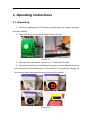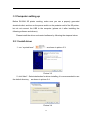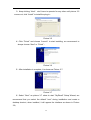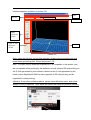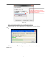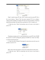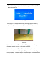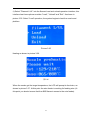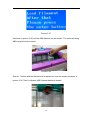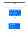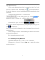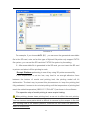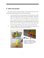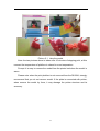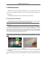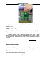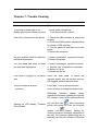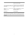
1
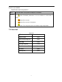
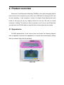
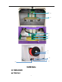
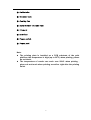
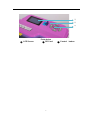
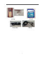
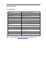
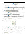
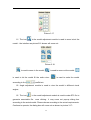
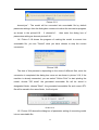
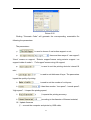
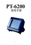
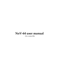
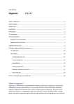
桌面式3D打印机 Riwell RL200A 使用手册 Desktop 3D Printer Riwell RL200A User Manual 句容利威尔电器有限公司 JuRong Riwell Electrical Co.,Ltd. 1. Introductions 1.1 Manual introduction This user manual includes product overview, operating instructions, printing and testing model, maintainance and troubleshooting, and others. Please read carefully and use the 3D printer according to the user manual. 1.2 Cautions 1.2.1 Safety attentions Jurong Riwell Electric Co., Ltd. does not recommend using other brands of consumable, in order to obtain optimal 3D printing results, please use the dedicated consumable supplied by Jurong Riwell Electric Co., Ltd. The maintainance and repair will not be included in the warranty which caused by using other consumable that not supplied by Jurong Riwell Electric Co., Ltd. Please do not touch when the machine is working or right after printing finish, the temperature of the model, nozzles, print platform or other parts of the internal body is high. 1.2.2 Contact Riwell If you are goint to contact Jurong Riwell Electric Co., Ltd., or seeking RL200A 3D printer driver, software, services or support, please visit http://www.myriwell.com 7. SD Card User's Guide: Regarding the usage and troubleshooting information you can find in the SD card attached in the accessories. 8. HTML (online) user guide: please visit Jurong Li Weier Electric Co. website http://www.myriwell.com. More information of usage and troubleshooting can be 2 found in our website. Identification and interpretation: Note The information of 3D printer is subject to our website. warning means Potentially hazardous, if not be avoided, it could result in injury means Do not touch means Do not touch for long time means The component parts are heated to high temperature 1.3 Item list Item list 3D printer 1 set Power cable 1 pcs USB connecting wire 1 pcs Tool bag 1 set Printing supplies 1 roll Qualification certificate 1 pcs SD card 1 pcs Packing list 1 pcs 3 2. Product overview Based on Fused Deposition Modeling, RL200A is the rapid prototyping device that connect to the computer to print online via a USB cable or through an SD card for print spooling. It can complete a variety of complex three-dimensional solid model of the print job only by copying Gcode file from the SD card to normal computer or laptop. This device is easy to operate, even if never used 3D printers you can also use RL200A easily to print all kinds of three-dimensional models. 2.1 Appearance RL200A appearances of the various parts are shown as following diagram (due to upgrade or optimize the appearance or internal structural changes, please take the material object as the standard). front view 4 ① ② ③ ④ ⑤ ⑥ ⑦ ⑧ ⑨ ⑩ RL200A Device ① Heating nozzle ② Printer bed 5 ③ Guide tube ④ Extruder hole ⑤ Cooling fan ⑥ Spool holder( Include nut) ⑦ Filam ent ⑧ Interface ⑨ Power switch ⑩ Power port Note: The printing plate is installed on a PCB substrate of the print platform, the temperature is high (up to 900C) when printing, please do not touch. The temperature of nozzle can reach over 2000C when printing , please do not touch when printing as well as right after the printing finish. 6 ① ② ③ ① LCD Screen Print device ② SD Card 7 ③ Control button Tool bag SD card Power cable USB line 8 2.2 specification 2.2.1 parameter RP Process FDM(Fused Deposition Modeling) Machine Size 570mm×515mm×470mm Packing Dimension 585mm×525mm×480mm Model Size 225mmx145mmx150mm Modeling Precision ±0.2mm/100mm Layer Thickness 0.15mm~0.4mm Modeling Speed 10~60mm/s Nozzle Dia. 0.4mm Velocity ±24cc/h Working Temp Extruder 180-260°C,Baseplate 60-110°C Material ABS/PLA White/Red/Yellow/Green/Black/Blue etc. Workstation Compatibility Windows®7/Windows®XP/Windows®Vista/Linux Interface USB Power Consumption 250W ,100-120/200-240VAC ,50/60Hz Operation Environment Temperature100C-32.50C Humidity 20%-80%(RH) Language Chinese/English File Format STL Weight 11kg(Net Weight)/13kg(Package Weight) Accessory Tools, consumable, SD card Note The above parameters are subject to updated information without notice. Please visit the our Web site http://www.myriwell.com for latest information. 9 2.2.3 Environmental specification Environmental specification Operating environment Storage environment installed in a well-ventilated, dust-free area。 temperature:15°C to 35°C humidity:20% to 80%(RH) temperature:0°C to 40°C humidity:10% to 80%(RH) non-corrosive gases existing and clean occasion Note The above parameters are subject to updated information without notice. Please visit the our Web site http://www.myriwell.com for latest information. 10 3. Operating instructions 3.1 Unpacking 1)Check the appearance of 3D printers, whether there are bumps, scratches and other defects. 2)Open the cover, cut out ribbon what it fasten extruder. Picture 3.1 3)Manually move the nozzle, check if its X, Y direction is flexible. 4)Remove the packet, pick the filament roll up, put it on the filament scroll and pull it through the wire feeding hole. As the picture 3.2, filament get through the wire guiding tube, then insert the hole at the top of the nozzle. ① ② ③ ④ Picture 3.2 11 3.2 Computer setting up Before RL200A 3D printer working, make sure you use a properly grounded electrical outlet, and turn on the power switch on the posterior wall of the 3D printer, but do not connect the USB to the computer (please do it after installing the following software and drivers). Please install the driver and control software by following the steps as below. 3.2.1 Install driver 1)run “myriwell.exe”: ,as shown in picture 3.3: Picture 3.3 2)click“Next”,Select destination for driver installing, it is recommended to use the default directory, as shown in picture 3.4: Picture 3.4 12 3)Keep clicking “Next”,don’t have to operate for any other until picture 3.5 comes out, click “Install” to install the plug-in: Picture 3.5 4)Click “Finish” and choose “Launch” to start installing, we recommend to always choose “Next” or “Finish”: Picture 3.6 5)After installation is complete, it is shown as Picture 3.7: Picture 3.7 6)Select "Next" as picture 3.7 show to start "MyRiwell" Setup Wizard, we recommend that you select the default "next" during installation and create a desktop shortcut, when installed, it will appear the interface as shown in Picture 3.8; 13 Picture 3.8 7)Clicking "finish" will end Myriwell 3D printing software installation as shown in picture 3.8. If you choose to create a desktop shortcut, complete, the desktop icon when the installation is will appear. 3.2.2 Install driver ; 1)Choose the driver installation folder 2)In the PL2303 driver folder, select one of the following two folders according ; to your computer's operating system 3)Enter the folder, you can directly click to install, if PL2303 driver has been installed in the system, we recommend that you uninstall the driver then restart the computer to install the driver again; 4)When driver installation is completed, connect the printer and computer by USD cable, when the electricity is turned on, check your computer's Device Manager, add new device port in the port directory : 3.2.3 Software description 1)After installing the software, click the icon 14 to run the software, the main interface appears, as shown in picture 3.9: Menu Tool bar File name Model adjustment module Angle of view View adjustment module Picture 3.9 Note: when the first time you run this program, please make sure select the print mode when generating files. Shown as picture 3.10: Note: The open source sofeware ReplicatorG37 is compatible in this printer, and we can operate online printing by this software, as well achieve SD card printing via the G code generated by this software; Moreover the G code generated by the latest version ReplicatorG-0040 is also supported in SD card printing (not be supported in online printing). Attention: If use these softwares above, please select Machine menu, and select teacip(112500) in Machine Type; Baud rate should be match for printer‘s firmware. 15 Advanced setting: It is use to adjust the parameters of printer to improve print quality,This option for professional user. Usually set defaults option. picture 3.10 Note:All of the firmware upgrades have to through Myriwell software. Otherwise the files will be generated and will not show as below picture 3.11: Picture3.11 2)Select the menu "File" the drop-down menu will come out as shown in picture 3.10: 16 Picture 3.12 "Open" is used to import STL files, "save" is used to save the current STL file in the current directory, "Recent Files" list recent imported STL file to software, "testing (model examples)" list sample STL files come with the software, "Restoring default printer settings" will clear all the records and exit, "Exit" is used to exit; 3)Select the menu "Code" the drop-down menu will come out as shown in picture 3.11: Picture 3.13 "Generate processing code" is used to generate the current STL file to GCODE file "print file" is used for printing after getting the GCODE file, "Pause" and "Stop" to control the printing process; 4)Select the menu "Myriwell Technology" the drop-down menu will come out as shown in picture 3.12: Picture 3.14 Select "New" and "most popular" to browse the website about the 3D printer; 5)Select the menu "Help" the drop-down menu will come out as shown in picture 3.13: 17 Picture 3.15 Select "Offline Documents" to open the note; 6)The icon in the tool bar is used to import the STL file, the icon used to start online printing, the icon is is used to update the firmware,the icon is used to select the machine you want to connect; 7) it shows the name of STL file; 8)The icon in the model adjustment module is used to move the drawing in the middle of the view, 9)The icon is used to cancel the operation; in the model adjustment module is used to move the model in the view,in the picture3.14 the three icons are used to move the model from X、Y、 Z three different ways,meanwhile we can drag the model by clicking the left mouse button. If choose the Z-axis height will be fixed when moving the model: Picture 3.16 10)The icon in the model adjustment module is used to rotate the model, as shown in the picture3.15 the three icons of X、Y、Z are Respectively used to rotate the model with ±90°. this icon is used to flat the model, meanwhile we can rotate the model with any angle by clicking the left mouse button。If choose ,the model will be rotated around the Z-axis fixedly: 18 Picture 3.17 11)The icon in the model adjustment module is used to zoom in/out the model,the interface as picture3.16 shown will come out: Picture 3.18 is used to zoom in the model, is used to zoom out the model, is used to let the model fill the entire view, according to the is used to scale the model coefficient; 12)Angle adjustment module is used to view the model in different visual angles; 13)The icon in the model adjustment module is used to make STL file to generate executable file,once clicking,it may come out pop-up dialog box according to the actual model,Please choose according to the actual requirements. Continue to operate, the dialog box will come out as shown in picture 3.17: 19 Picture 3.19 choose“yes”,The model will be converted into executable file by default parameter settings,then the dialog box comes out to show the conversion progress as shown in the picture3.18 ,if choose“no”, then enter the dialog box of parameters setting as shownin picture3.20. 14)Picture 3.18 shows the progress of making the model to convert into executable file, you can "Cancel" what you have chosen to stop the current conversion: Picture 3.20 The time of this process is depending on the sizes of different files, once the conversion is completed, the dialog box come out as shown in picture 3.19, if the machine is already connected, you can select "Online Print" to start printing the model; choose "SD mode" the generated executable file will be saved in designated folder; choose "Back", the generated executable file and current STL file will be saved in the same folder, it will not print. Picture 3.21 15)Picture 3.20 shows the dialog box of parameter setting of converting model into an executable file: 20 Picture 3.22 Clicking "Generate Code" will generate the corresponding executable file following the parameters. The parameters: ①、 is used to choose if use bottom support or not; ②、 there are three ways of “use support”: “None” means no support,“Exterior support”means using exterior support(no support inside of model),“Full support”means using full support; ③、 is used to set the printing device's internal fill rate; ④、 is used to set thickness of layer,The parameters impact the quality of printing. ⑤、 is used to set the number of out layers; ⑥、 it has three modes,“low speed”、“normal speed”、 “high speed”,it impact the printing speed; ⑦、 it impacts the printing accuracy; ⑧、 according to the diameter of filament material; 16)Update firmware ①、connect the computer and printer by USB cable; 21 ②、select the connect button in the tool bar the machine; ,till successfully connecting ③、select the button of update firmware in the tool bar ; At this point the software will remind "machine is connected, if you need to update the firmware, first disconnect" , select OK, and click disconnect. Then click ④ 、 click again, “Updata”, and wait till the process is finished, then the update firmware is completed; ⑤、After the update is complete then restart the machine, it will quit firmware update program and USB cable will be disconnected. 3.3 LCD display 3.3.1 Main interface Turn on the power, the main interface is shown as below。 Picture 3.23 3.3.2 Preparation 22 1) Once turn on the power, there are four modes on the LCD display: SD menu, print testing, system setting, company information, as shown in picture 3.24. Picture 3.24 2) The function of five buttons: up and down buttons are used to go up and down, left and right buttons are used to page-turning operation, middle button is used to confirm,shown as picture 3.25 picture3.25 3) If the SD card has been inserted in the machine, choose “SD menu” and you will see all the GCODE files in the root directory of SD card. Insert the SD card as shown picture 3.26, select “SD menu” and enter the root directory as shown picture 3.27. GCODE file will be shown as .G format. 23 picture3.26 picture3.27 4) It will start SD printing mode by choosing any GCODE file in SD menu; this is the display in SD menu as shown picture 3.28 picture3.28 5) In the SD card printing process, press the middle confirmation button, LCD screen will display relevant options of "Cancel Printing", confirm again will cancel the printing. picture3.29 24 Picture 3.30 6) In the main menu, select "Print Test" to enter the "Print Test" menu, shown as picture 3.31. picure 3.31 Select "Start" to start testing, printing graphics are a few lines, print testing can not be canceled. Print testing process displayed as shown in picture3.32. picture3.32 25 When Print testing is completed, it will display the printing is finished, LCD shown in picture 3.33. picture3.33 The performance of lines after testing shown as picture 3.34. When testing is completed, the system will be automatically homing, LCD display returns to the main menu. Picture3.34 7) In the main menu, select "Company Info", will display products and company information, press the enter key to return to the main menu. 8) In the main menu, select "System Settings" to enter the system setup menu, there are six modules shown in the System Settings menu : material handling, platform calibration, English (or Chinese), nozzle temperature, chassis temperature, and return, in which the return is used to return to the main menu. 26 9) Select "Filament L/UL" into the filament load and unload operation interface, this interface has three options modules "Load", "Unload" and "Exit." As shown in picture 3.35. Select "Load" operation, the system begins to heat the nozzle and platform. Picture 3.35 Heating as shown in picture 3.36. 图3.36 When the nozzle get the target temperature, the LCD will prompt to feed wire, as shown in picture 3.37. At this point the wire feeder is working for feeding wire (At this point you should ensure that the ABS filament access to the wire feeder). 27 Picture 3.37 As shown in picture 3.38, put the ABS filament into the nozzle. The motor will bring ABS material into the nozzle. Picture 3.38 Wait for 1 minute and the filament will be spitted out from the nozzle as shown in picture 3.39. Then it indicates ABS filament has been loaded. 28 Picture 3.39 Select "Unload filament", when the nozzle get the target temperature, the LCD prompt unloading wire, as shown in picture 3.37. At this moment the wire feeder reverses for retreating wire. When it is completed, press the enter key, the system returns to the System Settings menu. Picture 3.40 In the loading / unloading wire heating process, sometimes because of wrong operation or other reasons, if you want to cancel heating before the nozzle getting the target temperature, just press the enter key (as shown in picture 3.41) to cancel loading/unloading filament, and will return to the system setup menu. Picture 3.41 10)Select "Calibration" into the heating printer bed and calibration. The platform calibration function is mainly to adjust the space between the platform and nozzle 29 by rotating the screws on the platform, so as to achieve a good printing effect. The calibration interface platform has three options: Next, Previous and Confirm. Select the "Next" nozzle will move to the next set point; "Previous" to return to the previous set point; choose "Confirm", will default the platform calibration is completed, the system reset. This is shown in Picture 3.42and 3.43: picture 3.42 Rotate the adjustable screw Picture 3.43 After you have correctly calibrated your nozzle height,check that the nozzle is at the same distance at all four corners of the print platform and center of the print platform. If it is not, you may need to adjust the platform until it is level with the 30 nozzle at all 4 corners and center.There are 4 screw and 4 spring washers under the platform . Loosen a screw and the related corner of platform will rise. Tighten,or loosen,the screws until you have the same gap between the nozzle and the platform at all four corners of platform. An easy way to check the distance between the nozzle and platform is to fold a piece of paper in two (Which will make it about 0.2mm thick)and use that as a spacer to gauge the distance between the nozzle and platform. Note: when first time printing, make sure finish platform calibration! 11)If the system is in English, choose "Chinese", the system will automatically switch to the Chinese. If the system is in Chinese, choose "English", the system will automatically switch to the English. Language switching will be saved in the system. picture 3.44 picture 3.45 12)Select "nozzle temperature" or "bed temperature" will be used to set the head or printer bed target temperature, modify the number by using the direction keys. After setting, the target temperature will be saved in the system until the next setting. Because of the different target temperature corresponding to the different ABS material, we recommend when you use the new material, please adjust the target nozzle temperature in accordance with the actual effect. Nozzle temperature adjustment is shown in picture 3.46. 31 Picture 3.46 4.Print testing 4.1Ready for printing 4.1.1 Platform calibration In order to ensure the safety and printing precision, calibration must be performed in the first time before printing, in the calibration the epoxy board must be installed on the platform. For specific operation please check "3.32 Preparation" in No. 10); 4.1.2 Load ABS filament Loading filament can be divided into two steps, the first step put the ABS filament in the wire feeder through a wire casing, the second step is heating the nozzle until the ABS material is extruded from nozzle. The detailed operation of second step please check "3.32 Preparation" in No. 9); 4.1.3 Print testing After platform calibration and loading filament, we can check if the printer and the components is running normally by print testing, please check the specific operation "3.32 Preparation" in No. 6); 32 4.2 Print mode There are two kinds of work mode: 1. Online print, 2. Off-line print by SD card 4.2.1 Online print 1)Click the icon to run the software; 2)Clink the icon in the tool bar, connect the printer, the following prompt dialog box appear: When successfully connected, will show following prompt dialog box: Clink “OK”, the banner becomes it means the connection is OK; 3)After connection, the icon 4)Clink the icon in the tool bar comes high bright ; in the tool bar, select the STL file into the software; 5)When the model come out in the view, operate by “move”、 “rotate”、 “zoom”in the model adjustment module, adjust the model into a reasonable size, position and angle, we can view the model from different visual angle through 33 angle adjustment module; 6)When model adjustment is completed, we suggest that select ”save” in the “file” menu to save the model. Then clink the icon , generate executable file. We can take this process by using the default parameters or selecting the related parameters; 7)After generating code, if printer is connected, select to start printing by serial port, the icon will appear at the bottom of windows view, we have to wait for a moment; 8)After that it will appear the view like , meanwhile the LCD screen will show the printer is online printing. During the printing, you can clink to stop printing; Note: in the case of online printing, printing can not be stopped before printing with extruded filament! 9)When printing is completed, the prompt dialog box will show in the software to inform the time of printing. This is the operation brief of online print. 4.2.2 Off-line print by SD card 1) Operate by following the step 1) to step 4) in ”4.2.1 online print”; 2) After generating executable file, select as shown in picture4.4: 34 , it appears the interface Picture 4.4 For example, if you choose you can save the generated executable file in the SD card, note: so far this type of Myriwell 3d printer only support FAT32 file system, you can set the SD card into FAT32 file system by formatting; 3)After executable file is generated in the SD card, you can insert the SD card to printer and select off-line printing to work. Prompt: Platform preheating is one of key using 3D printer successfully If the temperature is set too low, may lead to no enough adhesion force between the bottom of model and printing bed, the printing model will tilt deformation. The best way to prevent this phenomenon is: keep the printing bed fully preheated, it means to do not start printing until the temperature of printing bed reach the setted temperature (ABS:110 ℃,PLA:60 ℃) as shown in the software. The operation step of model printing is same as print testing: After printing, please clean printing bed, so as not to affect the next printing. You can remove some parts which is difficult to remove by the scraper in the tool box. Printing bed is the heated platform, therefore do not touch the platform, in order to avoid burns. 35 1 2 5. Take the model After printing model, the printer will beep, nozzle and plate will return to the zero position and stop heating, system reset to the initial state. 1) Take the printer bed from the print platform of RL200A (that is the PCB board with regular mesh points as picture shown below). Holding the blade, put it between the model and platform, and slowly moving the shovel, prizing model back and forth. Remember that printer bed and platform has to stop heating, but it is still high temperature in a short time, beware of burns. If there is support part of the print model, support part removal can be operated by using a variety of tools in the accessory. 2) If there is support part of the print model, support part removal can be operated by using a variety of tools in the accessory. Loosen the binder clips , remove the PCB board after printing to remove printed models from the printer. 36 Picture 5.1 take the model Note: the two pictures above is taken after 10 minutes of stopping print, at this moment the temperature of platform is closed to room temperature. Prompt: it is easy to remove the model from the printer bed when the model is warm. Please note: when the print platform is not removed from the RL200A, strongly recommend that you do not remove model. If the plate is connected with printer, when remove the model by force, it may damage the printer structure and its accuracy. 37 Chapter 6: Maintenance 6. Maintainance RL200A does not need special maintenance, but it needs to paint the oil regularly on the principal axis and the screw rod to prevent premature aging of the moving parts. The following listed matter is that we should note and maintain: 6.1 Clean the Print Head Several times use later of printers, the print head will clog, you can use a clean, soft, damp cloth to clean the external three-dimensional printer. Attention: Do not use ammonia-based cleaners to clean the printer or around the printer. During the 3D printing process, some elements in the supplies, dust particles can accumulate inside the printer or print head. With the passage of time, the accumulation of material will cause print quality problems. Like print head clogging and no silk, silk Volume tumor. Printer you want to correct and avoid such problems, you can clean the print head and printer floor area. Clean the print head generally with tweezers to remove impurities. As shown below. Picture 6.1 If the nozzle clogged, we need to remove and clean the print head, the steps are as follows: 1) Adjust the printer bed to the lowest position, and select "loading filament", waiting for heating up to the setted temperature and buzzer. Extrude the filament by. 38 Chapter 6: Maintenance Picture 6.2 2) If we have diameter auger bit with diameter 0.3mm or the needle with diameter 0.3mm. 6.2 Belt Tensioning The flat belt is loose if you find belt bending the head or both sides of RL200A. Phenomena of the belt loose such as out of step, bounce, or print less the object within the shell surface. In addition, when the motor is selected the direction , there will be a certain amount of exercise is stored , then in the opposite direction with my hand , it can be run the right move, " bounce" may result in part of the structure of the print object inaccurate. Attention: more information about the tension belt, see www.myriwell.com. 6.3 Lubrication Guide In the course of work sounds very loud noise and vibrate powerful, you need to add oil to the rail. X, Y two axes rely on precision rails of 10mm diameter and Z-axis screw to ensure a smooth line movement without any swing. Add oil to reduce friction, reduce wear and tear caused by long-term exercise. The method: choose a clean cloth and painted lubricant on the rail and screw, then screw the lubricant on screw mandrel smoothly. 39 Chapter 7: Trouble Clearing Problems Frequently Questions Solution The printer 's power light is off Ready light of printer does not shine Can not be connected to the printer Check power whether on. Turn the power off , reboot 1. Check the UBS interface is connected properly 2. Check the USB interface corresponding to software COM interface 3. Turn the power off and then turn on the power 4. Restart the computer the print platform failed to reach the 1. Heater is damaged, replace the heater specified temperature 2. Restart the printer The print head has failed to reach 1. Heater is damaged, replace the heater the specified temperature 2. Replace the temperature resistance , as shown in Figure 3. Restart the printer Print head is clogged or no plastic Clean the print head, or adjust the wire squeeze plastic wire set screws, such as still clogged, replace the print head. The print model is skewed (crooked ) Loose belt , need to tension the belt Loose of motor or timing belt pulleys link. Reference firmware update mode, operate the firmware updating through the PC software. Note: in this case please do not clink the icon , after connecting Starting up LCD diaplay “Fireware printer with power on, click the firmware Error Updata” update icon directly. Setting by viewing the device manager equipment in the port, the firmware update plug-ins to manually set the port number in firmware 40 update, then start to update. Restart the printer in the case the the USB After connection with computer, pull cable does no insert the computer If first up the USD cable, the LCD screen time is not successful, you can try once become dark again Base layer curl or non-stick to print Whether the temperature of baseplate platform reaches the setting temperature Software don’t work Reinstall the software Other failures Technical Support Tips: Sometimes curling phenomenon will appear when pint the large model. This is caused by the printing platform surface uneven preheat. Before printing a large model, the warm-up is essential. In addition, the smaller the print model, the less curly part prone to appear. If possible, avoid printing large models as much as possible. 41 Chapter 8: Warranty Statement and License Agreement JuRong Riwell Electronics Co., Ltd. Limited Warranty Statement JuRong Riwell Electronic Co. Ltd. (short for Riwell) products of Myriwell 3D printer, one-year warranty to guarantee: Riwell hardware, accessories, and supplies from the purchase date in materials and workmanship does not exist on the defect. Riwell notice such defects during the warranty period, and repair or replace products which prove to be defective. Replacement products may be similar to the new product or performance of new products. In the case of correct installation and usage, Riwell guarantee from the purchase date of within the specified date, the software does not execute its programming instructions due to defects in materials and workmanship. During the warranty period, if Riwell notice such defects, Riwell replace execute its programming instructions software defected. We can’t ensure the operation of the product will be uninterrupted or without error. If Riwell within a reasonable period of time can not repair or replace the product warranty liability, the customer will be entitled to immediately return the product and request the refund of the purchase price. Our product may contain the re-production parts equivalent to new parts performance, or may be subject to incidental use parts. Warranty does not apply to a product defect caused by the following reasons: (a) maintenance or improper calibration or inadequate ; ( b ) the use of non-Riwell software, interfaces, components , or supplies; (c) unauthorized modification or misuse of equipment; (d) operation outside the environmental specifications for the product announced; (e) improper site preparation or maintenance . The extent permitted by local law, the above warranty is the only addition, express or implied, written or oral warranty or terms, and Riwell not propose guarantee terms for any particular purpose of merchantability, satisfactory quality and applications implied. Some countries / regions, states or provinces do not allow limit the implied warranty, so the above limitation or exception may not apply to you. This limited warranty gives you specific legal rights, you have other rights which may vary due to different countries / regions, states or provinces. The Riwell limited warranty applies to the product support services only in the country / region of selling the product. The level of warranty service may vary with the different local standards. Riwell will not alter the form, fit or function, so that it can be used for legal or regulatory reasons and the country / region which never intended. The extent allowed by local law, this Warranty Statement compensation is the only proprietary compensation. Apart from the above , the Riwell or its suppliers under any circumstances be liable for any data loss or direct, special, incidental, consequential (including loss of profits or loss of data ) or other responsible for any loss , whether it is based on contract , tort or for other reasons. Some countries / regions, states or provinces do not allow the exclusion or limitation of incidental or consequential damages, so the above limitation or exclusion may not apply to you. In addition to the extent permitted by law, the warranty terms of this statement does not exclude or limit or modify the mandatory statutory rights applicable of this product for such customers. 42