1
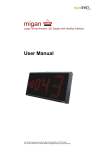
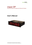
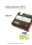
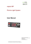
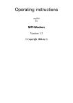
migan CAN
Large Format Numeric LED Display with CANopen Interface
User manual
microSYST Systemelectronic GmbH, Albert-Einstein-Straße 7, 92637 Weiden
Tel. +49 961 39166-0, Fax +49 961 39166-10, www.microsyst.de, [email protected]
migan CAN
Large Format Numeric LED Display with CANopen Interface
Index
1
GENERAL
4
2
TECHNICAL INFORMATION
5
3
4
2.1
Device Configuration
6
2.2
Connector Pin Assignments
7
2.3
Interface Settings (CAN)
8
2.4
Internal Settings
10
2.5
Device Start
11
CANOPEN INTERFACE
12
3.1
CANopen Protocol
3.1.1 NMT Frames
3.1.2 Nodeguard Frame
3.1.3 Heartbeat Frame
3.1.4 SDO Frames
3.1.5 Receive PDO Frame
3.1.6 Transmit PDO Frame
12
12
13
13
14
14
14
3.2
Notes for CAN Controlling
15
3.3
Transmit Frame (CAN -> migan)
16
3.4
Receive Frame (migan -> CAN)
18
3.5
Controlling Example
19
CONTROL DATA
20
4.1
Control Frame (Display Output)
20
4.2
Response Frame
23
Page 2
microSYST Systemelectronic GmbH, Albert-Einstein-Straße 7, 92637 Weiden
Tel. +49 961 39166-0, Fax +49 961 39166-10, www.microsyst.de, [email protected]
migan CAN
Large Format Numeric LED Display with CANopen Interface
5
APPENDIX
24
5.1
Displayable characters
24
5.2
Protocol “Classic” (Previous Version)
25
5.3
General notes
29
5.4
Declaration of Conformity
30
5.5
Warranty / Liability
31
5.6
Versions overview
32
Page 3
microSYST Systemelectronic GmbH, Albert-Einstein-Straße 7, 92637 Weiden
Tel. +49 961 39166-0, Fax +49 961 39166-10, www.microsyst.de, [email protected]
migan CAN
Large Format Numeric LED Display with CANopen Interface
1 General
This 7 segment displays are designed for professional use. Depending on the
type of device they are suitable for indoor or outdoor use.
The modular design allows for cost-effective models of various interfaces with different character heights and numbers of digits.
Change of the Controlling Protocol!
The displays use a new controlling protocol.
Due to the advanced possibilities, we recommend the use of this new option.
By default, the displays are already set to this new universal protocol.
For compatibility reasons, however, the “old” controlling can be activated
by a switch.
For details, refer to chapter “Protocol Classic”.
Page 4
microSYST Systemelectronic GmbH, Albert-Einstein-Straße 7, 92637 Weiden
Tel. +49 961 39166-0, Fax +49 961 39166-10, www.microsyst.de, [email protected]
migan CAN
Large Format Numeric LED Display with CANopen Interface
2 Technical Information
Display type:
Character heights:
Number of digits:
Number of lines:
Display colour:
Operating voltage:
View:
Interface:
Displayable characters:
Labelling:
Housing:
Housing colour:
Mounting:
Protection:
Operating temp.:
Storage temp.:
7 segment LED
Indoor use: 60 / 100 / 150 / 200 / 250 mm
Outdoor use: 100 / 200 / 300 mm
1...40
Standard 1 line, multiple lines on request
Standard red, other colours on request
230 VAC / 50 Hz, 110 VAC / 60 Hz or 24 VDC ±20%
Single sided to four sided
CANopen (according to the specifications below)
see corresponding chapter
on request
Industrial version, powder coated aluminum
RAL 7016 (anthracite)
Articulated arm, angle bracket, hanging on chain or
mounting frame
see chapter “Device Configuration“
see chapter “Device Configuration“
-25 ... +70 °C
Interface Specifications
Interface:
Bitrate:
Node ID:
PDOs:
PDO linking:
PDO mapping:
Node guarding:
Heartbeat:
CANopen per CIA standard DS301, V4.02
10...1000 kBit/s (DIP switch)
1...127 (DIP switch)
1 receive PDO, 1 transmit PDO
yes (COB IDs for utilised PDOs can be adjusted via SDO)
fixed
yes
yes
Page 5
microSYST Systemelectronic GmbH, Albert-Einstein-Straße 7, 92637 Weiden
Tel. +49 961 39166-0, Fax +49 961 39166-10, www.microsyst.de, [email protected]
migan CAN
Large Format Numeric LED Display with CANopen Interface
2.1 Device Configuration
Type:
for inside use
for outside use
Character height:
60 mm
100 mm
150 mm
Number of lines: ________
200 mm
250 mm
Number of digits per line: ________
Display colour:
red
green
yellow
View:
single sided
double sided
four sided
Operating voltage:
230 VAC / 50 Hz
110 VAC / 60 Hz
24 VDC
Protection:
IP40
IP65
IP54
Operating temperature:
with type for inside use:
0...+50 °C (standard)
Housing dimensions:
Housing Material:
Aluminum profile
300 mm
white
blue
IP _____
with type for outside use:
-20...+50 °C (standard)
-25...+50 °C (optional with heating)
_________x_________x_________mm
Stainless steel
Sheet metal
CANopen Interface:
Factory settings:
Baud rate:
10 kBaud
250 kBaud
20 kBaud
500 kBaud
50 kBaud
800 kBaud
125 kBaud
1000 kBaud
Device address (Node ID): ________Hex
Protocol (at delivery):
Universal (standard)
Classic
Page 6
microSYST Systemelectronic GmbH, Albert-Einstein-Straße 7, 92637 Weiden
Tel. +49 961 39166-0, Fax +49 961 39166-10, www.microsyst.de, [email protected]
migan CAN
Large Format Numeric LED Display with CANopen Interface
2.2 Connector Pin Assignments
Please see inside labelling of the mating plug for pin assignment.
Power Connector 230 VAC
Pin
1
2
(PE)
Assignment
L1
N
PE
Power Connector 24 VDC (optional)
Pin
1
2
3
Assignment
GND
+24 VDC
PE
Pin
1
2
3
4
5
6
7
8
9
Assignment
CAN
CAN_L
CAN_GND
CAN_Shield
GND
CAN_H
Page 7
microSYST Systemelectronic GmbH, Albert-Einstein-Straße 7, 92637 Weiden
Tel. +49 961 39166-0, Fax +49 961 39166-10, www.microsyst.de, [email protected]
migan CAN
Large Format Numeric LED Display with CANopen Interface
2.3 Interface Settings (CAN)
S1
S3
S2
Status LEDs
Status LEDs
LED
green (RUN)
red (RS/ERROR)
yellow (CAN)
Status
Normal operation: blinking
RS communication: flickering
Error:
ON
CAN frame received or transmitted => 100 ms ON
Page 8
microSYST Systemelectronic GmbH, Albert-Einstein-Straße 7, 92637 Weiden
Tel. +49 961 39166-0, Fax +49 961 39166-10, www.microsyst.de, [email protected]
migan CAN
Large Format Numeric LED Display with CANopen Interface
DIP Switches
DIP switch settings are specified below (0 = OFF and 1 = ON).
DIP switch settings are read in once only during power-up (after switching the
device on).
CAN Node ID (S1):
7
6
5
0
0
0
0
0
0
0
0
0
DIP
4
CAN Node-ID
3
2
1
0
0
0
1
1d
0
0
1
0
2d
0
0
1
1
3d
:
:
1
1
1
1
1
1
1
127d
Note: Only addresses 1 through 127 are permissible!
CAN-Bitrate (S1):
10
DIP
9
CAN Bit Rate
8
0
0
0
0
1
1
1
1
0
0
1
1
0
0
1
1
0
1
0
1
0
1
0
1
1000 kBit/s
800 kBit/s
500 kBit/s
250 kBit/s
125 kBit/s
50 kBit/s
20 kBit/s
10 kBit/s
CAN BusTermination (S3):
(has to be set, if the device is first or last device at the CAN bus)
DIP
1
0
1
CAN Bus Termination
2
0
1
not set
set
RS Settings (S2):
Basic setting: DIP3 and DIP4 in position ON, remaining switches in position OFF.
Page 9
microSYST Systemelectronic GmbH, Albert-Einstein-Straße 7, 92637 Weiden
Tel. +49 961 39166-0, Fax +49 961 39166-10, www.microsyst.de, [email protected]
migan CAN
Large Format Numeric LED Display with CANopen Interface
2.4 Internal Settings
S5
S6
S4
S5
LED
S2
S1
S3
Options (S4)
S4-DIP
1
2
3
4
5
6
7
8
OFF
ON
Baud rates 1200...9600
Data format: 7 bits
without response frame
Baud rates 19200...115200
Data format: 8 bits
with response frame
Protokoll: Universal
Protocol: Classic
DIP2 is ignored (8 bits, fixed)
fixed value (55H) instead of checksum
use checksum
(only with protocol “Universal“)
(only with protocol “Universal“)
Brightness control for inside displays
Brightness control for outside displays
Temperature/brightness sensor: Master Temperature/brightness sensor: Slave
Evaluation of migra frames
Standard
(AD, IZ, BCD)
* Marked positions are set per default.
Page 10
microSYST Systemelectronic GmbH, Albert-Einstein-Straße 7, 92637 Weiden
Tel. +49 961 39166-0, Fax +49 961 39166-10, www.microsyst.de, [email protected]
migan CAN
Large Format Numeric LED Display with CANopen Interface
LED
This green LED blinks with 2 Hz, if processor is running.
Factory Settings:
S2 = „0“
S1 = „1“
S3 = „D“
S5: DIP1 = ON
DIP2 = ON
2.5 Device Start
• Segment test
• <first 2 digits of the baud rate > <parity> <data bits>
• A<display address>
This parameters refer to the internal interface and are not significant for
CANopen operation.
Page 11
microSYST Systemelectronic GmbH, Albert-Einstein-Straße 7, 92637 Weiden
Tel. +49 961 39166-0, Fax +49 961 39166-10, www.microsyst.de, [email protected]
migan CAN
Large Format Numeric LED Display with CANopen Interface
3 CANopen Interface
3.1 CANopen Protocol
The interface is driven via the CANopen interface as defined in CIA DS301,
V4.02 (CAN in Automation e.V., Erlangen, Germany).
The protocols integrated into the device are described briefly below.
3.1.1 NMT Frames
Start remote node
Stop remote node
Enter pre-operational state
Reset node
Reset communication
COB ID
000 h
000 h
000 h
000 h
000 h
B.1
1
2
128
129
130
B.2
0 / node ID
0 / node ID
0 / node ID
0 / node ID
0 / node ID
B.3 B.4 B.5 B.6 B.7 B.8
-
All CANopen nodes are in one of the following operating states:
“INITIALISATION”, “PRE-OPERATIONAL”, “OPERATIONAL” or
“STOPPED”.
After power-up, the INITIALISATION state is executed and entries in the
object index are set to their default values.
Either all communications-specific entries, or only those included in the
object index (1000 h -1FFF h), can be reset to their default values at any time
with the help of the “reset node” and “reset communication” commands.
The device then enters the “PRE-OPERATIONAL” state.
The device is switched to the OPERATIONAL state after issuing the “start
remote node” command.
The device can be switched to the stopped state through use of the “stop
remote node” command.
Return to the PRE-OPERATIONAL state is made possible with the “enter
pre-operational state” command.
Page 12
microSYST Systemelectronic GmbH, Albert-Einstein-Straße 7, 92637 Weiden
Tel. +49 961 39166-0, Fax +49 961 39166-10, www.microsyst.de, [email protected]
migan CAN
Large Format Numeric LED Display with CANopen Interface
3.1.2 Nodeguard Frame
Receive
Response
COB ID
700 h +
node ID
RTR=1
DLC=1
700 h +
node ID
RTR=0
DLC=1
B.1
-
B.2
-
B.3
-
B.4
-
B.5
-
B.6
-
B.7
-
B.8
-
128 x toggle bit (0 or 1) +
current operating state:
4:
STOPPED
5:
OPERATIONAL
127: PRE-OPERATIONAL
-
-
-
-
-
-
-
The “nodeguard” frame may only be used when “heartbeat” is inactive
(“producer heartbeat time” = object 1017 h = 0).
When “life-guarding” is activated (“guard time” = object 100C h > 0 and “life
time factor” = object 100D h > 0), a timer is started each time a nodeguard
request occurs, which automatically switches the device to the PREOPERATIONAL state after “life time” has elapsed (“guard time” x “life time
factor” ms), if the next nodeguard request is not received on time.
3.1.3 Heartbeat Frame
Response
COB ID
700 h +
node ID
RTR=0
DLC=1
B.1
Current operating state:
0:
BOOTUP
4:
STOPPED
5:
OPERATIONAL
127: PRE-OPERATIONAL
B.2
-
B.3
-
B.4
-
B.5
-
B.6
-
B.7
-
B.8
-
The “boot-up” frame is transmitted after the device is switched on (operating
state = “BOOTUP”).
After selecting the setting “producer heartbeat time” = object 1017 h (unit of
measure: ms), the device starts transmitting the heartbeat frame in a cyclical
fashion.
Page 13
microSYST Systemelectronic GmbH, Albert-Einstein-Straße 7, 92637 Weiden
Tel. +49 961 39166-0, Fax +49 961 39166-10, www.microsyst.de, [email protected]
migan CAN
Large Format Numeric LED Display with CANopen Interface
3.1.4 SDO Frames
“Initiate download
request”
“Initiate download
response”
“Initiate upload
request”
“Initiate upload
response”
“Abort domain
transfer”
(receive SDO)
“Abort domain
transfer”
(send SDO)
COB ID
600 h+
node ID
B.1
22 h
or
23 h + *
60 h
580 h+
node ID
600 h+
node ID
580 h+
node ID
600 h+
node ID
40 h
43 h+ *
80 h
580 h+
node ID
80 h
B.2
Index LOW
B.3
Index HIGH
B.4
Subindex
B.5
D0
(LSB)
B.6
D1
B.7
D2
B.8
D3
(MSB)
Index LOW
Index LOW
Index LOW
Index LOW
Index HIGH
Index HIGH
Index HIGH
Index HIGH
Subindex
0
0
0
0
Subindex
0
0
0
0
D0
(LSB)
Subindex Additional
code
D1
D2
0
Error
code
D3
(MSB)
Error
class
Index LOW
Index HIGH
Subindex Additional
code
0
Error
code
Error
class
Subindex
* 4 times “number of unused data bytes”
The object index of all CANopen nodes can be accessed with the help of the
SDO frame.
3.1.5 Receive PDO Frame
RPDO1
COB ID
200 h +
node ID
B.1
send
data 1
B.2
send
data 2
B.3
send
data 3
B.4
send
data 4
B.5
send
data 5
B.6
send
data 6
B.7
send
data 7
B.8
send
data 8
RPDO1 is mapped to object 2000 h, subindex 1 through 8.
RPDO1 must be transmitted to the interface (repeatedly), in order to generate a
complete frame.
3.1.6 Transmit PDO Frame
TPDO1
COB ID
180 h +
node ID
B.1
RS
receive
data 1
B.2
RS
receive
data 2
B.3
RS
receive
data 3
B.4
RS
receive
data 4
B.5
RS
receive
data 5
B.6
RS
receive
data 6
B.7
RS
receive
data 7
TPDO1 is mapped to object 2001h, subindex 1 through 8.
TPDO1 is received as an answer, after a valid frame has been sent.
Page 14
microSYST Systemelectronic GmbH, Albert-Einstein-Straße 7, 92637 Weiden
Tel. +49 961 39166-0, Fax +49 961 39166-10, www.microsyst.de, [email protected]
B.8
RS
receive
data 8
migan CAN
Large Format Numeric LED Display with CANopen Interface
3.2 Notes for CAN Controlling
Before data can be sent to the display, CANopen state “OPERATIONAL”
must be activated. After that, data are transmitted with the help of RPDO1 in
the form of sub-frames. Please notice that at the first sub-frame the toggle
bit = 1. After data evaluation, the display answers with TPDO1 (here, first
toggle bit = 1 too).
Page 15
microSYST Systemelectronic GmbH, Albert-Einstein-Straße 7, 92637 Weiden
Tel. +49 961 39166-0, Fax +49 961 39166-10, www.microsyst.de, [email protected]
migan CAN
Large Format Numeric LED Display with CANopen Interface
3.3 Transmit Frame (CAN -> migan)
Receive PDO 1 (object 2000h, subindex 1 through 8)
Byte
1
2
3
4
5
6
7
8
Function
Function byte:
• Bit 7:
end bit
• Bit 6
=0
• Bit 5
=0
• Bit 4:
toggle bit
• Bit 3
=0
• Bits 2...0: sub-frame length
Sub-frame byte 1
Sub-frame byte 2
Sub-frame byte 3
See chapter
Sub-frame byte 4
“Control Frame
Sub-frame byte 5
(Display Output)“
Sub-frame byte 6
Sub-frame byte 7
Toggle Bit:
Each time the toggle bit is changed, the current sub-frame is added to the
end of the transmit buffer.
End Bit:
= 0:
Sub-frames are accumulated.
= 1:
Accumulated sub-frames are transmitted (including the subframe which has just been transferred if the toggle bit has also
been changed).
The transmit buffer is cleared after transmission has been
completed (in order to be able to store new sub-frames), and the
end bit is set to 0 (in order to be able to detect the end of the
transmit procedure via SDO).
Sub-Frame Length:
Length of the transferred sub-frame
Sub-Frame Bytes:
They are added to the end of the frame which has already been transferred
to the transmit buffer when the toggle bit is changed.
Page 16
microSYST Systemelectronic GmbH, Albert-Einstein-Straße 7, 92637 Weiden
Tel. +49 961 39166-0, Fax +49 961 39166-10, www.microsyst.de, [email protected]
migan CAN
Large Format Numeric LED Display with CANopen Interface
Procedure at the CANopen Side for Transmitting a Frame:
1. Break down the control frame into sub-frames of max. 7 bytes each.
2. Transfer the sub-frames to the display.
• Prepare the contents of the PDO to be transmitted:
• Enter frame bytes of the sub-frame to be transmitted to PDO bytes 2
through max. 8.
• PDO byte 1:
• Enter “sub-frame length” (1 to 7).
• Change the “toggle bit”.
• Set the “end bit” to 1, if no additional sub-frame needs to be
transmitted.
• Transmit the PDO.
• Wait until the PDO has been transmitted.
• Wait additional 5 ms.
• Repeat the last 4 steps until all sub-frames have been transferred.
3. Wait for the answer (TPDO1).
Page 17
microSYST Systemelectronic GmbH, Albert-Einstein-Straße 7, 92637 Weiden
Tel. +49 961 39166-0, Fax +49 961 39166-10, www.microsyst.de, [email protected]
migan CAN
Large Format Numeric LED Display with CANopen Interface
3.4 Receive Frame (migan -> CAN)
After evaluation of the control frame, the display responds with following
Transmit PDO:
Transmit-PDO 1 (Objekt 2001 h, Subindex 1 bis 8)
Byte
1
2
3
4
5
6
7
8
Function
Function byte:
• Bit 7:
=1
• Bit 6
=0
• Bit 5
=0
• Bit 4:
toggle bit
• Bit 3
=0
• Bits 2...0: frame length
Response frame byte 1
Response frame byte 2
Response frame byte 3
See chapter
Response frame byte 4
“Response Frame“
Response frame byte 5
Response frame byte 6
Response frame byte 7
Toggle Bit:
Changes with every received response frame
Frame Length:
Length of the current transferred response frame
Response Frame Bytes:
According to chapter “Response Frame”
Page 18
microSYST Systemelectronic GmbH, Albert-Einstein-Straße 7, 92637 Weiden
Tel. +49 961 39166-0, Fax +49 961 39166-10, www.microsyst.de, [email protected]
migan CAN
Large Format Numeric LED Display with CANopen Interface
3.5 Controlling Example
For details see chapter “Control Data”.
The use of the protocol “universal” is required (standard, see chapter “General”).
All values are written in hexadecimal notation.
Requirements:
o CANopen node ID: 01
o Display with 3 digits
o Show value “1.23”
o Data type: unsigned CHAR
• Initialise the node (if it is not yet “OPERATIONAL”):
Transmit NMT frame (COB ID = 000h):
01 01
• Transmit RPDO1 frame (COB-ID = 201h), last toggle bit was 0.
17 01 06 00 30 80 00 7B
\/ \/ \_________/ \/
| |
|
|
| LEN
O1…O4 “123”
|
ADR
• Wait at least 5 ms.
• Transmit RPDO1 frame (COB-ID = 201h):
81 55 00 00 00 00 00 00
\/
|
CHK
• Receive TPDO1 frame (COB-ID = 201h), last toggle bit was 0:
94 01 02 00 55 00 00 00
Note
At start-up, the device must already be connected to an active CAN bus.
Else, a CAN error would appear with transmission of the Boot-Up-Message.
Page 19
microSYST Systemelectronic GmbH, Albert-Einstein-Straße 7, 92637 Weiden
Tel. +49 961 39166-0, Fax +49 961 39166-10, www.microsyst.de, [email protected]
migan CAN
Large Format Numeric LED Display with CANopen Interface
4 Control Data
Following chapters describe the current controlling with the protocol “universal” (see also chapter “General”).
4.1 Control Frame (Display Output)
ADR
Device address
01H
LEN
Number of following
bytes (from O1 to CHK)
06H ... n
►
O1
Options
Bit 7: report software version*
Bit 6: 0 = Statically display the last received
data (standard)
1 = Display “----“, if no new data is
received within 5 s.
Bits 5...4: Brightness
00 = 100%
01 = 80%
10 = 60%
11 = 40%
Bit 3 = Digital output 4
Bit 2 = Digital output 3
Bit 1 = Digital output 2
Bit 0 = Digital output 1
Output will be set, if corresponding bit = 1
* at communication with response frame
Page 20
microSYST Systemelectronic GmbH, Albert-Einstein-Straße 7, 92637 Weiden
Tel. +49 961 39166-0, Fax +49 961 39166-10, www.microsyst.de, [email protected]
migan CAN
Large Format Numeric LED Display with CANopen Interface
►
O2
Output format
Bits 7...4: Physical number of digits (bit coded)
0001...1111 = 1...15 digits
0000
= ASCII representation with up to 40 digits
Bit 3:
Mode
0 = LSB first
1 = MSB first
Bits 2...0: Data type*
max. number of digits
000 = unsigned CHAR (0...255)
3
001 = unsigned INT (0...65535)
5
010 = unsigned LONG (0...4294967296)
10
011 = signed CHAR (-128...127)
4
100 = signed INT (-32768...32767)
6
101 = signed LONG (-2147483648... 2147483647) 11
110 = ASCII representation
40
111 = reserved
* at value representation: right-aligned display
at ASCII representation: left-aligned display
O3
Decimal points
Bit 7 =
Bit 6 =
Bit 5 =
Bit 4 =
Bit 3 =
Bit 2 =
Bit 1 =
Bit 0 =
Point for digit 1
Point for digit 2
Point for digit 3
Point for digit 4
Point for digit 5
Point for digit 6
Point for digit 7
Point for digit 8
O4
Decimal points, blinking
Bit 7 =
Bit 6 =
Bit 5 =
Bit 4 =
Bit 3 =
Bit 2 =
Bit 1 =
Bit 0 =
►
Point for digit 9
Point for digit 10
Point for digit 11
Point for digit 12
Point for digit 13
Point for digit 14
Point for digit 15
Display blinks
A point is set, if corresponding bit = 1
Page 21
microSYST Systemelectronic GmbH, Albert-Einstein-Straße 7, 92637 Weiden
Tel. +49 961 39166-0, Fax +49 961 39166-10, www.microsyst.de, [email protected]
migan CAN
Large Format Numeric LED Display with CANopen Interface
D1…Dn
Data bytes (value- or ASCII representation)
Value representation:
CHAR value: 1 byte
INT value:
2 bytes
LONG value: 4 bytes
CHK
Checksum
depending on S4-DIP5:
standard: 55H (fixed value)
or
LOW byte of the sum of all previous bytes (ADR...Dn)
ASCII representation (max. 80 bytes):
1 byte per character, max. 40 digits,
Bit 7 = 1: digit blinks
The decimal point has character code 2CH or
2EH and is always set at the previous digit.
Controlling devices with multiple display areas (e.g. 2 lines):
The partition from O2…Dn is used repeatedly according to the number of
display areas (see example 3).
Please attend to the maximum total frame length of 150 bytes.
Example 1:
Display with 4 digits, device address 1, unsigned INT (LSB first), brightness =
60%, display value = 1.23
01 07 20 41 40 00 7B 00 55
Example 2:
Display with 4 digits, device address 1, ASCII representation, brightness = 60%,
display value = 12.34
01 0A 20 46 00 00 31 32 2E 33 34 55
Example 3:
Display with 2 lines and 4 digits per line, device address 1, unsigned INT (LSB
first),
display value for line 1 = 1.23,
display value for line 2 = 5.67
01 0C 00 41 40 00 7B 00 41 40 00 37 02 55
\______________/\______________/
Line 1
(O2...D2)
Line 2
(O2...D2)
Page 22
microSYST Systemelectronic GmbH, Albert-Einstein-Straße 7, 92637 Weiden
Tel. +49 961 39166-0, Fax +49 961 39166-10, www.microsyst.de, [email protected]
migan CAN
Large Format Numeric LED Display with CANopen Interface
4.2 Response Frame
Digital inputs are optionally available (depending on display type).
ADR
Device address
LEN
Length
01H
02H
I1
Digital Input
Bit 7 = Event digital input 4
Bit 6 = Event digital input 3
Bit 5 = Event digital input 2
Bit 4 = Event digital input 1
Bit 3 = Status digital input 4
Bit 2 = Status digital input 3
Bit 1 = Status digital input 2
Bit 0 = Status digital input 1
CHK
Checksum
depending on S4-DIP5:
standard: 55H (fixed value)
or
LOW byte of the sum of all previous bytes
(ADR + LEN + I1)
Event of a digital input = 1, if it has been set at least once since the last query (f.e. with a button).
The event is deleted after every query.
Status of a digital input = 1, if it’s set at the moment.
Example
Digital input 3 is set
01 02 04 55
Page 23
microSYST Systemelectronic GmbH, Albert-Einstein-Straße 7, 92637 Weiden
Tel. +49 961 39166-0, Fax +49 961 39166-10, www.microsyst.de, [email protected]
migan CAN
Large Format Numeric LED Display with CANopen Interface
5 Appendix
5.1 Displayable characters
The data bytes are ASCII coded:
Lower
Higher
0
0
1
2
3
4
5
6
“Blank”
1
2
3
4
5
6
7
8
9
A
B
C
D
E
F
Page 24
microSYST Systemelectronic GmbH, Albert-Einstein-Straße 7, 92637 Weiden
Tel. +49 961 39166-0, Fax +49 961 39166-10, www.microsyst.de, [email protected]
7
migan CAN
Large Format Numeric LED Display with CANopen Interface
5.2 Protocol “Classic” (Previous Version)
Basically, we recommend the current controlling which is described in the
chapter “Control Data”.
For compatibility reasons with already delivered devices, the previous protocol and
inteface properties are still integrated and can be activated by a switch.
Depending on the device interface, different switches are used:
S4
S3
S3 = E, all switches of S4 = OFF
Page 25
microSYST Systemelectronic GmbH, Albert-Einstein-Straße 7, 92637 Weiden
Tel. +49 961 39166-0, Fax +49 961 39166-10, www.microsyst.de, [email protected]
migan CAN
Large Format Numeric LED Display with CANopen Interface
Display Output
STX
Start of transmission
3CH (or 02H)
ADRH*
Device address HIGH
30H
ADRL*
Device address LOW
31H
►
P1
P2
P3
►
Point byte 1
Point byte 2
Point byte 3
Bits 7...5 = 010
Bits 7...5 = 010
Bits 7...5 = 010
Bit 4 = Point for digit 1
Bit 3 = Point for digit 2
Bit 2 = Point for digit 3
Bit 1 = Point for digit 4
Bit 0 = Point for digit 5
Bit 4 = Point for digit 6
Bit 3 = Point for digit 7
Bit 2 = Point for digit 8
Bit 1 = Point for digit 9
Bit 0 = Point for digit 10
Bit 4 = Point for digit 11
Bit 3 = Point for digit 12
Bit 2 = Point for digit 13
Bit 1 = Point for digit 14
Bit 0 = Point for digit 15
To display a point, the corresponding bit must be set.
D1...Dn
ETX
Data bytes
End of transmission
One byte per character to be displayed; ASCII coded
3EH if STX = 3CH
Bit 7 = 1: Digit blinks
= 0: Digits is shown statically
(03H if STX = 02H)
The decimal point has character code 2CH or 2EH and
is set at the former digit each.
Writing direction is from the left to the right.
Example 1
Display “1.23“, decimal point is controlled via the point bytes
3C 30 31 50 40 40 31 32 33 3E
Example 2
Display “1.23“, decimal point as ASCII character via the data bytes
3C 30 31 40 40 40 31 2E 32 33 3E
Page 26
microSYST Systemelectronic GmbH, Albert-Einstein-Straße 7, 92637 Weiden
Tel. +49 961 39166-0, Fax +49 961 39166-10, www.microsyst.de, [email protected]
migan CAN
Large Format Numeric LED Display with CANopen Interface
Digital Outputs, Brightness
Digital outputs are optionally available (depending on display type).
The display content is not changed after this frame.
STX
Start of transmission
ADRH
Device address HIGH
ADRL
Device address LOW
3CH (or 02H)
30H
31H
O1
O2
O3
ETX
Digital outputs
Brightness
reserved
End of transmission
Bits 7...4 = 0110
Bits 7...4 = 0110
Bit 3 = Digital output 4
Bit 2 = Digital output 3
Bit 1 = Digital output 2
Bit 0 = Digital output 1
Bit 3: report software
version*
60H
3EH if STX = 3CH
(03H if STX = 02H)
Bit 2 = 0
Output will be set, if
corresponding bit = 1
Bits 1, 0: Brightness
00 = 100%
01 = 80%
10 = 60%
11 = 40%
* at communication with response frame
Example
Set digital output 2, brightness = 80 %
3C 30 31 62 61 60 3E
Page 27
microSYST Systemelectronic GmbH, Albert-Einstein-Straße 7, 92637 Weiden
Tel. +49 961 39166-0, Fax +49 961 39166-10, www.microsyst.de, [email protected]
►
migan CAN
Large Format Numeric LED Display with CANopen Interface
Response Frame
The response frame can be activated with a DIP switch.
Digital inputs are optionally available (depending on display type).
STX
Start of transmission
ADRH
Device address HIGH
ADRL
Device address LOW
30H
31H
►
3CH (or 02H)
= STX from the control
protocol
I1
I2
I3
ETX
Status of digital inputs
Events of digital inputs
reserved
End of transmission
Bits 7...4 = 0100
Bits 7...4 = 0100
Bit 3 = Digital input 4
Bit 2 = Digital input 3
Bit 1 = Digital input 2
Bit 0 = Digital input 1
Bit 3 = Digital input 4
Bit 2 = Digital input 3
Bit 1 = Digital input 2
Bit 0 = Digital input 1
3EH (oder 03H)
40H
= ETX from the control
protocol
Status of a digital input = 1, if it’s set at the moment.
Event of a digital input = 1, if it has been set at least once since the last query (f.e. with a button).
The event is deleted after every query.
Example
Digital input 4 was set at least once since last query
3C 30 31 40 48 40 3E
Page 28
microSYST Systemelectronic GmbH, Albert-Einstein-Straße 7, 92637 Weiden
Tel. +49 961 39166-0, Fax +49 961 39166-10, www.microsyst.de, [email protected]
migan CAN
Large Format Numeric LED Display with CANopen Interface
5.3 General notes
Please observe the following instructions:
•
When installing the device, always make sure that the installed
housing can be opened for adjustment or maintenance work. When
attaching the device, leave an appropriate space on the back / front
/ top to ensure adequate ventilation (if available).
•
Direct exposure to light sources or direct sun rays reduces the
reading quality.
•
Turn the device off for cleaning.
•
Protect the device from excessive moisture, strong vibrations, direct
sun exposure and extreme temperatures. If this is not observed, it
can cause function problems or device destruction. In addition,
there is the danger of electric shock, fire or explosion. Please refer
to "Technical Information" chapter for detailed information regarding
proper ambient conditions, especially recommended temperature
ranges.
•
The device may not be used if there is any damage on the device
and / or power line.
•
Do not attempt to repair the device yourself. Any interference by
unauthorized personnel will void the warranty.
Page 29
microSYST Systemelectronic GmbH, Albert-Einstein-Straße 7, 92637 Weiden
Tel. +49 961 39166-0, Fax +49 961 39166-10, www.microsyst.de, [email protected]
migan CAN
Large Format Numeric LED Display with CANopen Interface
5.4 Declaration of Conformity
EG-Konformitätserklärung
Declaration of EC-Conformity
Produktbezeichnung:
Product name:
migan CAN
Produktbeschreibung:
Product description:
Numerische LED-Großanzeige mit CANopen-Schnittstelle/
Large Format Numeric LED Display with CANopen Interface
Hersteller:
Manufacturer:
microSYST Systemelectronic GmbH
Albert-Einstein-Straße 7
92637 Weiden
Das bezeichnete Produkt stimmt mit
der folgenden Europäischen Richtlinie
überein:
We herewith confirm that the above mentioned product meets the requirements of
the following standard:
Die Übereinstimmung des bezeichneten
Produktes mit den Vorschriften der Richtlinie wird nachgewiesen durch die vollständige Einhaltung folgender Normen:
Nummer
Europäische Norm
EN61000-6-2:2006
EN61000-6-4:2007
2004/108/EG
Bezeichnung
Elektromagnetische
Verträglichkeit (EMV)
The correspondence of the above mentioned product with these requirements is proved by the fact that these products meet with the following
single standards:
Weiden, den 09.07.2013
Harald Kilian
Geschäftsführer / General Manager
Page 30
microSYST Systemelectronic GmbH, Albert-Einstein-Straße 7, 92637 Weiden
Tel. +49 961 39166-0, Fax +49 961 39166-10, www.microsyst.de, [email protected]
migan CAN
Large Format Numeric LED Display with CANopen Interface
5.5 Warranty / Liability
For the product, liability is assumed for defects, which existed at the delivery date according to our General Terms and Conditions.
Technically changes as well as errors are excepted. A claim for delivery
of a new product does not exist. The buyer has to check the received
product immediately and indicate evident defects at the latest 24 hours
after detection. Non-observance of notification requirements is equated
with acceptance of the defect. Not immediately visible defects have to
be indicated immediately after their perception too.
Generally, defects and their symptoms must be described as accurately
as possible in order to allow for reproducibility and elimination. The buyer must provide for access to the relevant device and all required and/or
useful information at no charge and must make all of the required data
and machine time available free of charge.
The guarantee does not cover defects, which result from nonobservance of the prescribed conditions of use, or from improper handling.
If the device has been placed at the disposal of the buyer for test purposes and has been purchased subsequent to such testing, both parties
agree that the product is to be considered “used” and that it has been
purchased “as is”. No guarantee claims may be made in such cases.
The General Terms and Conditions of microSYST Systemelectronic
GmbH in current version apply as well.
Page 31
microSYST Systemelectronic GmbH, Albert-Einstein-Straße 7, 92637 Weiden
Tel. +49 961 39166-0, Fax +49 961 39166-10, www.microsyst.de, [email protected]
migan CAN
Large Format Numeric LED Display with CANopen Interface
5.6 Versions overview
Version
Date
Remarks, Description
1.00
19.12.13
1.10
22.01.14
Document created, based on X-M32-BSXX6X-001:
Modifications for migan 2
migan 2 -> migan
1.20
30.10.14
Basic setting of interface switch S2
Certified per DIN EN ISO 9001.
Page 32
microSYST Systemelectronic GmbH, Albert-Einstein-Straße 7, 92637 Weiden
Tel. +49 961 39166-0, Fax +49 961 39166-10, www.microsyst.de, [email protected]