1
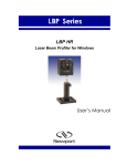
Optical Beam Position – Analog version User’s Manual EU Declaration of Conformity This is to certify that the accompanying product, identified with the CE mark, complies with requirements of the Electromagnetic Compatibility Directives. Model name: OBP Series Year CE mark affixed: 1996 Type of equipment: An optical beam position system, analog version. The device is constructed from a sensor head with an attached cable, electronics box and power supply. Has been tested and was found to comply with the requirements of: • EN 50081 : : “Electromagnetic Compatibility (EMC); generic immunity standard”, Part 1: Residential, Commercial and Light Industry. • EN 50082 : “Electromagnetic Compatibility (EMC); generic immunity standard”, Part 1: “Residential, commercial and light industry”. The undersigned hereby declare that the equipment specified above conforms to the above directive(s) and standard(s). Alain Danielo Dan Dunahay VP European Operations Director of Quality Systems Zone Industrielle 1791 Deere Avenue 45340 Beaune-la-Rolande, France Irvine, Ca. USA 2 Warranty Newport Corporation warrants that this product will be free from defects in material and workmanship and will comply with Newport’s published specifications at the time of sale for a period of one year from date of shipment. If found to be defective during the warranty period, the product will either be repaired or replaced at Newport’s option. To exercise this warranty, write or call your Newport office or representative, or contact Newport headquarters in Irvine, California. You will be given prompt assistance and return instructions. Send the product, freight prepaid, to the indicated service facility. Repairs will be made and the instrument returned freight prepaid. Repaired products are warranted for the reminder of the original warranty period or 90 days, whichever first occurs. Limitation of Warranty The above warranties do not apply to products which have been repaired or modified without Newport’s written approval, or products subjected to unusual physical, thermal or electrical stress, improper installation, misuse, abuse, accident or negligence in use, storage, transportation or handling. This warranty also does not apply to fuses, batteries, or damage from battery leakage. THIS WARRANTY IS IN LIEU OF ALL OTHER WARRANTIES, EXPRESSED OR IMPLIED, INCLUDING ANY IMPLIED WARRANTY OF MERCHNATABILITY OR FITNESS FOR A PARTICULAR USE. NEWPORT CORPORATION SHALL NOT BE LIABLE FOR ANY INDIRECT, SPECIAL, OR CONSEQUENTIAL DAMAGES RESULTING FROM THE PURCHASE OR USE OF ITS PRODUCTS. First printing 2003 2003 by Newport Corporation, Irvine, CA. All rights reserved. No part of this manual may be reproduced or copied without the prior written approval of Newport Corporation. This manual has been provided for information only and product specifications are subject to change without notice. Any change will be reflected in future printings. Newport Corporation 1791 Deere Avenue Irvine, CA 92606 USA 3 Confidentiality & Proprietary Rights Reservation of Title: The Newport programs and all materials furnished or produced in connection with them (“Related Materials”) contain trade secrets of Newport and are for use only in the manner expressly permitted. Newport claims and reserves all rights and benefits afforded under law in the Programs provided by Newport Corporation. Newport shall retain full ownership of Intellectual Property Rights in and to all development, process, align or assembly technologies developed and other derivative work than may be developed by Newport. Customer shall not challenge, or cause any third party to challenge the rights of Newport. Preservation of Secrecy and Confidentiality and Restrictions to Access: Customer shall protect the Newport Programs and Related Materials as trade secrets of Newport, and shall devote its best effects to ensure that all its personnel protect the Newport Programs as trade secrets of Newport Corporation. Customer shall not at any time disclose Newport’s trade secrets to any other person, firm, organization, or employee than does not need (consistent with Customer’s right of use hereunder) to obtain access to the Newport Programs and Related Materials. These restrictions shall not apply to information (1) generally known to the public or obtainable from public source; (2) readily apparent from the keyboard operation, visual display, or output reports of the Programs; (3) previously in the possession of Customer or subsequently developed or acquired without reliance on the Newport Programs; or (4) approved by Newport for release without restriction. Service Information This section contains information regarding factory service for the source. The user should not attempt any maintenance or service of the system or optional equipment beyond the procedures outlined in this manual. Any problem that cannot be resolved should be referred to Newport Corporation. 4 Technical Support Contacts North America & Asia Europe Newport Corporation Service Dept. Newport/Mcro-Controle S.A. 1791 Deere Ave. Zone Industrielle Irvine, CA 92606 45340 Beaune la Rolande. France Telephone: (949) 253-1694 Telephone: (33) 02 38 40 51 49 Telephone: (800) 222-6440 x31694 Asia – Newport Opto-Electronics Technologies 253 Aidu Road, Bold #3, Flr 3, Sec C, Shanghai 200131, China Telephone: +86-21-5046 2300 Fax: +86-21-5046 2323 Newport Corporation Calling Procedure If there are any defects in material or workmanship or a failure to meet specifications, promptly notify Newport’s Returns Department by calling 1-800-222-6440 or by visiting our website at www.newport.com/returns within the warranty period to obtain a Return Material Authorization Number (RMA#). Return the product to Newport Corporation, freight prepaid, clearly marked with the RMA# and we will repair or replace it at our discretion. Newport is not responsible for damage occurring in transit and is not obligated to accept products returned without an RMA#. E-mail: [email protected] When calling Newport Corporation, please provide the customer care representative with the following information: • Your Contact Information • Serial number or original order number • Description of problem (i.e., hardware or software) To help our Technical Support Representative diagnose your problem, please note the following conditions: • Is the system used for manufacturing or research and development? • What was the state of the system right before the problem? • Have you seen this problem before? If so, how often? • Can the system continue to operate with this problem? Or is the system nonoperational? • Can you identify anything that was different before this problem occurred? 5 Table of Contents Page EU Declaration of Conformity…………………………………………………………… 2 Warranty…………………………………………………………………………………… 3 Confidentiality & Proprietary Rights……………………………………………………. 4 Technical Support Contacts………………………………………………………………5 1. Introduction……………………………………………………….………………7 2. Specifications……………………….……………………………………………9 3. Dimensions and Drawings…………………………………………………….. 13 4. Operation…………………..……………………………………………………. 14 5. Accessories………………………………………………………….………….. 18 6. Troubleshooting…………………..…………………………………………….. 18 List of Figures Figure 1 OBP main components………………………………………………...8 Figure 2 Head drawing OBP-A-9L and OBP-A-9H………………………… 12 Figure 3 Head drawing OBP-A-4L and OBP-A-4H………………………….. 13 Figure 4 Electronics box…..……………………………………………………. 14 Figure 5 Timing Diagram…………………………………………………………15 Figure 6 Connection method of OBP………………………………………… 16 6 1. 0 Introduction OBP is a complete solution for fast and extremely accurate laser position sensing. Main Features: - Versatile – Measures both Position and Power using two-dimensional position sensitive detectors, either a 9mmx9mm or a 4mmx4mm , Lateral Effect PSD type. - - Precise – Large area detection with sub-micron resolution and linearity better than 0.5% - Easy to use – Just connect the output to a scope or DVM to observe movement in µm units (1Volt=1000µm) Compact – Slim design sensor heads and electronics box Main Applications: - Measure laser displacement in real time, at a rate of up to 60 KHz bandwidth - Measure fast steering mirrors - Monitor vibration and deflection at high bandwidth from long stand-offs - Perfect for close loop applications Figure 1: OBP main components Contents: Models OBP-A-4L or OBP-A-4H: Electronics box, PSD with 3m long attached cable, power supply, power cords (X2), Hood, carrying case, user manual, final testing and compliance verification Models OBP-A-9L or OBP-A-9H: Electronics box, PSD with 3m long attached cable, power supply, power cords (X2), carrying case, user manual, final testing and compliance verification 7 1.1 Precautions OBP system is a precision instrument and in normal usage will provide years of trouble free operation. However, a few precautions must be taken: • The instrument must not be subjected to physical abuse. If either the electronics box or detector heads are dropped they might be damaged. • Temperature and moisture extremes can also damage the instruments. Make sure there is adequate ventilation for the electronics box. • When not in use, keep a cap over the sensor heads to prevent dust from accumulating on the sensors. Dust, scratches and other types of contamination will degrade the accuracy of the system. • Do not touch the detector surface by bare fingers The operator should observe all laser safety procedures when operating the system. Note that a portion of the laser beam incident on the sensors will be reflected. This can be hazardous and the operator should beware of both specular and diffuse reflections. 1.2 Revision History Any new editions of this manual will incorporate all material updated since the previous edition. Update packages issued between editions contain replacement and/or additional pages to be appended to the current edition The manual printing date indicates its current edition. Updates and corrections to the current edition will be indicated: Dec 2004 – Revision 1.0 Sep 2006 – Revision 2.0 8 2.0 Specifications 2.1 General Parameters Symbols Value Power Supply Voltage Vs ±18V Operating Temperature Topt 0° - 50° C Current Consumption Is ±15mA 2.2 Model numbers and ordering information Newport Model Number Description OBP-A-4L Laser Position Sensor, 4mm Head, 10-2500µW (Low Amplification) OBP-A-4H Laser Position Sensor, 4mm Head, 1-250µW (High Amplification) OBP-A-9L Laser Position Sensor, 9mm Head, 10-2500µW (Low Amplification) OBP-A-9H Laser Position Sensor, 9mm Head, 1-250µW (High Amplification) 2.3 General Specifications Newport Model Number OBP-A-4L Sensor size PSD Mechanical dimensions Power Input Range Resolution (CW/Pulsed) Operating Temperature Range OBP-A-9L 9H OBP-A- 4X4mm 9X9mm 16mm dia. X 10mm deep 37mm dia. X 11mm deep 10-2500µW Response time OBP-A-4H 1-250µW <20 µS 1 mV / 5 mV 0 - 50ºc 10-2500µW 1-250µW <60µS 1 mV / 5 mV 0 - 50ºc Conversion factor: 1 mV = 1 µm Range (X,Y): ± 2000 V (or ± 2000 µm) for the 4mmx4mm PSD (OBP-A-4L or OBP-A-4H) ± 4500 V (or ± 4500 µm) for the 9mmx9mm PSD (OBP-A-9L or OBP-A-9H) 9 Wavelength: 350 – 1100 nm 2.4 Power Supply Specifications The OBP Series contain a universal desktop switching power supply, having the following specifications: Input Voltage: 90-264 Vac typical Input Frequency: 47-63Hz EMI: Meet EN55022 /FCC Class B Output Wattage: 10W Line Regulation: 0.1% typical Load Regulation: +/-1.5 – 3% typical Noise & Ripple: Typical 1% peak to peak Safety Standard: UL1950/EN60950 Class II 10 3.0 Dimensions and Drawings 3.1 9mmX9mm head (140 Gram with cable) Models OBP-A-9L and OBP-A-9H Figure 2: Head drawing OBP-A-9L and OBP-A-9H 11 3.2 4mmX4mm head (120 Gram with cable) Models OBP-A-4L and OBP-A-4H Figure 3: Head drawing OBP-A-4L and OBP-A-4H 12 3.3 Electronics box (125 Gram) Figure 4: Electronics Box 13 4.0 Operation Before using the OBP device please pay attention to the following issues: • The input beam should not exceed 100mW/cm2, otherwise the electronics/detector might be damaged. Timing Diagram Figure 5: Timing Diagram 14 4.1 Output Schematics The following block diagram illustrates the connection and operation method of OBP system: Figure 6: Connection method of OBP • Connect the power supply • Connect two Voltmeters, one for X measurement and one for Y measurement. Alternatively, you can connect a dual-channel Voltmeter • Connect the PSD head to the manifold box • Place the laser beam in front of the PSD, while making sure the beam is shined exactly at the detector’ center • Make sure that the laser power is not exceeding the OBP model (High Attenuation / Low Attenuation, see Specifications section 2.0) Things need your attention before conducting a measurement: • Make sure the beam is aligned close to the detector’ center and not shined at the detector’ edges • Make sure the two LED’s on the manifold box are lighted up. If not – there might be some fault operation of the unit, or a wrong voltage was applied 15 • Make sure the PSD is not saturated, if necessary mount a filter in front of the PSD. Saturating non-linear effects might occur (see General Specifications). Check saturation at Power Pin; if reading exceeds 10V than the electronics is saturated. • Make sure there is no ambient light affecting your measurement, check the ambient light at Power Pin (the voltage output value should be held to ±10 mV). Design an appropriate lightshielding to maintain this illumination level, or use the hood offered as the system’ accessories. The following diagrams present the effect of ambient light on the measurement accuracy: Figure 7: Ambient light effect on measurement accuracy 16 5.0 Accessories - A variety of ND filters in housing (C-Mount). Filters include: NG4, NG9, NG10 - Additional hood (55mm length) for ambient light suppression is included in models OBP-A-9L and OBP-A-9H - The power supply is provided with 2 cords: one for 110Vac and one for 220Vac. 6.0 Troubleshooting - No measurement: Check that your laser beam is On and shined into the PSD center Check that your laser beam power is above 40 mV - Erroneous measurement Check that your beam is not saturated, mount an ND filter if necessary Check that the ambient light is not reaching the PSD and provide a proper light-shielding Check the timing diagram and compare to your beam pulse width: the pulse width should be bigger than the response time - No LED light on manifold box Check that your power supply is connected properly and is On Check the voltage connection (check that +/- polarization was not switched) 17 18