1
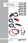
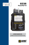
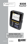
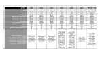
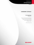
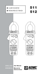
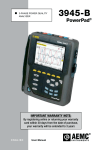
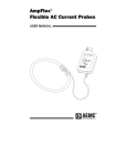
Power & Energy Logger PEL 100 Series Models PEL 102 & PEL 103 All You Need For Power & Energy Logging IP 54 Rated Economical Compact Simple To Use ► Simple to use, single-, dual- (split-phase) and three-phase (Y, ∆) power and energy loggers ► Designed to work in 1000V CAT III and 600V CAT IV environments and fits in many distribution panels ► Power measurements: VA, W and var ► Energy measurements: VAh, Wh (source, load) and varh (4 quadrants) ► DataView® software for data storage, real-time display, analysis and report generation with supplied pre-defined or custom templates ► Minimal programming required ► Ethernet compatible ► Bluetooth Class 1 wireless communication up to 300 feet away ► Satisfies the requirements of NEC 220.87 SA FET Y TM RA TIN G Our products are backed by over 100 years of experience in test and measurement equipment, and encompass the latest international standards for quality and safety. Technical Hotline: (800) 343-1391 www.aemc.com ETHERNET . PEL 100 Series: MODELS PEL 102 & 103 SD card back to a PC. The comprehensive DataView® software (included) provides the ability to view data from several hundred PEL 100 series instruments on a local network or over the internet, allowing the user to evaluate energy usage in a department or facility basis, a remote site, or even in a city, anywhere in the world. DataView® allows measurements to be viewed in real-time on a PC and stored data to be downloaded for analysis and report generation. Model PEL 102 Model PEL 103 The PEL 100 series is a low cost, simple to use, single-, dual- (split-phase) and three-phase (Y, ∆) power and energy data logger. There are two models available; Model PEL 102 (no display) and Model PEL 103 (with a backlit digital display). This product is ideal for electricians, engineers and contractors doing work in the area of building and system monitoring and upgrades, as well as residential and overall energy audits. All vital energy data is easily measured, recorded, and analyzed. Reports can be generated with confidence, with minimal configuration time and effort (Standard and Customizable Reports supplied). The PEL 100 series has many up-to-date features demanded by the present market conditions for energy and power consumption information needs. The instrument’s design enables it to be installed inside a load center panel (including the current sensors) allowing the door to close on most panels. The PEL 100 series offers all the essential functions for logging power and energy data from most electrical power networks in use today, across the world (17 network set-ups provided). The PEL 100 series power and energy loggers measure and record three voltage inputs and current inputs, Watts, VARS, VA and Energy (kWh and kVA). Power Factor (PF), Displacement Power Factor (DPF), Crest Factor, Frequency and THD are calculated and recorded, as well. Individual harmonic % information from 1 to the 50th harmonic are recorded at the operator’s choice. All variables are recorded and stored at a one second interval and on user selectable demand intervals from 1 to 60 minutes. Energy costs can be calculated and displayed quickly and easily by simply inputting the unit cost for a kilowatt hour into the software. Data is stored on a removable SD card. Data can be retrieved using a USB cable, Bluetooth and/or the Ethernet (local or internet) connection or by transporting the 2 www.aemc.com Configuration of the PEL 100 series instruments is accomplished through DataView® software either locally or remotely. Most of the configured parameters are pre-set in the instrument, keeping the user interface very simple and straightforward. Current probes are automatically detected and scaled to a pre-defined or user specified configuration when connected to the instrument. User selections include network type, demand interval, recording length, voltage and current ratios (where necessary), recording duration (defined either by time and/or date) and communication method. Password protection can be configured for Bluetooth and network communication to guard against unauthorized access and protection of data integrity. The DataView® software provides the ability to view power, harmonic (for AC measurements) and RMS, as well as DC data in real-time and download recorded sessions for more extensive analysis and report generation. One second trend data, demand interval trend graphs and tabular listings can be displayed and printed. Energy costs can be calculated from the downloaded session. Source and load graphs can be plotted. Individual phase and the sum of all phases can be evaluated. Once data is downloaded and displayed, the user has access to a variety of tools to analyze individual data points or sections of the recorded data without the frustration of having to deal with layers of button pushing. This simple to use yet comprehensive power and energy logger will be an invaluable asset to your power and energy monitoring and analysis needs. The PEL 100 series energy loggers can safely and easily facilitate voltage and current hook-ups. Technical Assistance (800) 343-1391 FEATURES, NETWORKS & APPLICATIONS FEATURES ►Simple to use, single-, dual- (split-phase) and three-phase (Y, ∆) power and energy loggers ►Provides all the necessary functions for Power and Energy data logging for 50Hz, 60Hz, 400Hz and DC distribution systems ►Current measurements from 200mA DISTRIBUTION SYSTEMS SUPPORTED ►.Single-Phase 2-Wire ►.Single-Phase 3-Wire (Split-phase from a center tap transformer) Three-Phase 3-Wire Power Networks up to 10,000A using flexible current sensors ►.Three-phase 3-wire ∆ (with two current sensors) ►Power measurements: VA, W and var ►.Three-phase 3-wire Open ∆ (with two current sensors) ►Energy measurements VAh, Wh (source/load indication) and varh (including quadrant indication) ►.Three-phase 3-wire ∆ (with three current sensors) ►.Three-phase 3-wire Open ∆ (with three current sensors) ►.Three-phase 3-wire Y (with two current sensors) ►Record cost of energy usage ►.Three-phase 3-wire Y (with three current sensors) ►Power Factor (PF), Cos (ϕ), Tan (Φ) ►.Three-phase 3-wire ∆ Balanced (with one current ►Crest Factor Three-phase 4-Wire Y Power Networks and DPF sensor) ►Total Harmonic Distortion (THD) for ►.Three-phase 4-wire Y (with three current sensors) voltages and currents ►.Three-phase 4-wire Y Balanced ►Harmonics up to the 50th order for ►.Three-phase 4-wire Y 2½ Element 50/60Hz voltages and currents and 7th order for 400Hz ►Frequency measurements ►.Three-phase 4-wire ∆ ►.Three-phase 4-wire Open ∆ ►Simultaneous RMS measurements of each phase @ 128 samples/cycle and DC DC Power Networks ►Bright blue, four line LCD on the Model ►.DC 3-wire PEL 103 (3 phases shown simultaneously) ►Storage of measured and calculated ►.DC 2-wire ►.DC 4-wire ►Automatic recognition of the connected current sensors/probes APPLICATIONS ►Configuration of current and voltage ratios ►Measure efficiency and find areas for potential savings to external PT and CT ratios ►Track sub-billing occupants for energy costs ► 17 types of hook-ups for supported electrical distribution systems ►Assign energy costs to departments or operations within a department ►USB, LAN, and Bluetooth communication ►Track peak demand periods and find opportunities for surcharge reductions values on a SD-Card or SDHC-Card ►Includes DataView® software for data storage, real-time display, analysis and report generation with supplied pre-defined or custom templates ►Determine present capacity and circumvent unnecessary electrical expansion costs ►Verify the reliability and operation of electrical machinery ►Improve response time to solve power related problems ►Track energy availability and reliability of supply ►Reduce field service time at sub-stations ►Baseline studies for system upgrades in high-rise and office buildings Technical Assistance (800) 343-1391 www.aemc.com 3 SPECIFICATIONS GENERAL Sampling Frequency Data Storage Rate Demand Period Storage Rate Recorded Parameters (Single- and Poly-Phase) Event Log Front Panel Indicator LEDs Storage Capacity INPUTS Voltage Current 128 samples per cycle; 50/60Hz (16 samples/cycle 400Hz) 1 per second User selectable (1, 2, 3, 4, 5, 6, 10, 12, 15, 20, 30 and 60 minutes) V, I, W, VA, var, PF, Tan, Wh, Vah, varh, THD (V and I), Individual harmonics (from 1 through 50 per phase); Crest Factor (CF), Cos f / DPF Tracks and records status changes and error messages along with recorded data Bluetooth active, recording in progress, phase connection reversal, overload, battery charging and SD Card status 2GB SD card (included) is used for storage. SD cards (up to 2GB); SDHC cards (4 to 32GB) formatted FAT32 are supported 3 voltage input channels via 4mm safety banana jacks 3 current input channels via custom 4 pin jacks that accept AEMC® probes and sensors shown on page 5 ELECTRICAL VOLTAGE MEASUREMENT 50/60Hz Single-Phase RMS Voltages Phase-to-Phase RMS Voltages 400Hz Single-Phase RMS Voltages Phase-to-Phase RMS Voltages DC PT Ratios CURRENT MEASUREMENT Current Probe: MiniFlex® Sensor MA193 *** For further specifications and other compatible current probes, see chart on page 5 CT Ratios POWER MEASUREMENTS Active Power (P)* Reactive Power (Q)* Apparent Power (S)* Power Factor Tangent φ (active/reactive power ratio) ENERGY MEASUREMENTS Active Energy (EP) Reactive Energy (EQ) Apparent Energy (ES) HARMONICS THD Individual Harmonics External Supply Back-Up Power Source / Charge Time Battery Life RANGE 42.5 to 69Hz 10 to 1000Vrms 17 to 1700Vrms 340 to 460Hz 10 to 600Vrms 17 to 1200Vrms 100 to 1000V Programmable from 50V to 65,0000V (primary and secondary) RESOLUTION – 0.1V 0.1 to 1V – 0.1V 0.1 to 1V 0.1V * ACCURACY (% of Reading) ±0.1Hz ±0.2% Rdg ± 0.2V ±0.2% Rdg ± 0.4V – ±1% Rdg ± 1V ±1% Rdg ± 1V ±1% Rdg ± 3V (typical) 0.01V to 0.1V – 200mA to 100Arms 0.8A to 400Arms 4A to 2000Arms 20A to 10,000Arms 1 to 100mA 10 to 100mA 0.1 to 1A 0.1 to 10A Programmable from 1:1 to 25,000:1 (probe dependent) ±1.2% ± 50mA ±1.2% ± 0.2A ±1.2% ± 1A ±1.2% -2 to 2GW -2 to 2Gvar 0 to 2GVA -1 to +1 -3.2 to +3.2 0.001W 0.001var 0.001VA 0.001 0.001 ±0.5% Rdg ± 0.005% Pnom ±1% Rdg ± 0.01% Qnom ±0.5% Rdg ± 0.005% Snom ± 0.05 ± 0.02 0 to 4 x 10¹⁸ 0 to 4 x 10¹⁸ 0 to 4 x 10¹⁸ 1Wh 1varh 1Vah ±0.5% Rdg ±2% Rdg ±0.5% Rdg ± 655% 1 to 50 displayed in percentage; 1 to 7 at 400Hz 110V/250V (10%) @ 50/60Hz; 400Hz Rechargeable 8.4V NiMH battery pack / Approximately 5 hours Provides up to 30 minute ride through upon power loss MECHANICAL Communication Ports Dimension/Weight Case / Index of Protection Mounting Security USB 2.0, Ethernet (RJ45), Wireless Bluetooth Class 1 ** 10.08 x 4.92 x 1.46" (256 x 125 x 37mm) / <1kg Double insulated, rubber over-molded polycarbonate UL94 V1 rated / IP54 non operating Embedded magnets on back side, keyhole slot on back side Kensington anti-theft system DISPLAY Display Type for Model PEL 103 2.63 x 2.16" (67 x 55mm), four line, monochrome, backlit LCD with adjustable brightness and contrast ENVIRONMENTAL Operating Temperature / Relative Humidity Storage Temperature 32° to 122°F (0° to 50°C) / up to 85% -4° to 122°F (-20° to 50°C) with batteries; -4° to 158°F (-20° to 70°C without batteries) SAFETY Safety Rating / CE Rating Complies with IEC 61010-1:Ed3, and IEC 61010-2-030:Ed1 for 1000V CAT III / 600V CAT IV, Pollution Degree 2 / CE Marked * Maximum value is current probe dependent. ** Computers with Class II Bluetooth will restrict range to 40ft. Computers without Bluetooth will require a Class I or Class II Bluetooth radio adapter. *** Maximum current reduced by a factor of 2 for 400Hz fundamental frequency. 4 www.aemc.com Technical Assistance (800) 343-1391 PROBES & SENSORS A complete family of current measurement probes to meet most AC or DC measurement applications up to 10,000Arms. Sensor Type MiniFlex® MA193 * 10" Sensor Typical Maximum Error Error on φ at on φ at 50/60Hz 50/60Hz RMS or DC Current Accuracy 100Aac 200mA to 120A ±1% ± 50mA 0° ±0.5° -0.5° 400Aac 20 to 500A ±1% ± 0.2A 0° ±0.5° -0.5° 2000Aac 100 to 2400A ±1% ± 1A 0° ±0.5° -0.5° 10,000Aac 500 to 12,000A ±1% 0° ±0.8° -0.5° 50 to 100A ±1.5% ± 1A -0.90° ±2.5° 100 to 800A ±2.5% -0.80° 800 to 1000A ±4% -0.65° 50 to 100A ±0.5% +0.25° ±1° 100 to 1200A ±0.3% +0.2° ±0.7° 100Aac 5 to 120A ±1% ± 50mA 0° ±0.5° -0.5° 400Aac 20 to 500A ±1% ± 0.2A 0° ±0.5° -0.5° 2000Aac 100 to 2400A ±1% ± 1A 0° ±0.5° -0.5° 10,000Aac 500 to 12,000A ±1% 0° ±0.5° -0.5° 5 to 40A ±2.5% ± 1A +2° ±5° -1.5° @ 40A 40 to 100A ±2% ± 1A +1.2° ±3° -0.8° @ 100A 100 to 240A ±1% + 1A +0.8° ±2.5° -1° @ 200A MR193 1000Aac/dc SR193 ±2° 1000Aac AmpFlex® 193 * 24" Sensor 36" Sensor MN93 200Aac MN193 Typical Error on φ at 400Hz Nominal Current 1.6" (41mm) +0.1° @ 1000A 2.05" (52mm) 100Aac 5 to 120A ±1% +0.75° ±2.5° -0.5° @ 100A 5A 5Aac 250mA to 6A ±1% +1.7° ±5° -0.5° @ 5A 5 to 40A ±4% ± 50mA – ±1° – 10A 100Aac/dc 40 to 100A ±15% – ±1° – 50mA to 10A ±3% ± 50mA – ±1.5° – 100A 10Aac/dc 2.75" (70mm) -4.5° @ 100A 100A SL261 ** Max Conductor Size 7.64" (190mm) 11.46" (290mm) 0.78" (20mm) 0.78" (20mm) 0.46" (11.8mm) * Maximum current reduced by a factor of 2 for 400Hz fundamental frequency. ** AC/DC Current Probe BNC Adapter for Model SL261 only Catalog #2140.40 Technical Assistance (800) 343-1391 www.aemc.com 5 MODEL PEL 103 LCD DISPLAY Key Features of the PEL 103 Display Measured Phase Indicator Measurement Values Information Display Bar Bargraph (Load factor - Min - Max). The bargraph indicates the percentage (0% to 100%) of full range or full load as programmed into the PEL by the user through the DataView® software. Measurement Units Measurements or Page Title Mode Selection Display Bar Top and Bottom Display Bars Indicate the Following ICON DESCRIPTION Phase Sequence reversal indicator or missing phase (displayed in 3-Phase distribution systems) Data available for recording (non-display indicates possible internal problem) Power Quadrant Indication Measurement Mode (Real Time values) Power and Energy Mode Harmonics Mode Min/Max Mode Information Mode Not used The backlit display on the Model PEL 103 can be read in dark areas showing the real-time measurements. 6 www.aemc.com Technical Assistance (800) 343-1391 FUNCTIONAL DISPLAYS Harmonic Mode The PEL 103 display provides real-time information for all the measured and calculated values that are recorded. The left/right navigation button scrolls through the display modes while the up/down navigation button scrolls through the available real-time measurements for the selected display mode. Total Harmonic Distortion (THD) can be displayed by phase or phase to phase. Neutral current THD can also be displayed. Measurement Mode Min/Max Mode Real-time updates are displayed for voltage, current, power, frequency, power factor and tangent. Min/Max values for voltage, current (including neutral current), power and harmonics. Energy Mode Information Mode press 2s Real and apparent energy can be displayed along with an indicator identifying whether the energy is used by the load or supplied back to the source. Reactive energy can also be displayed with source/load, capacitive or inductive properties indicated. In this display the network hook-up, PT and CT primary and secondary values can be displayed as well as the IP address (if connected to the Ethernet), Software and Firmware version and serial number. press 2s Technical Assistance (800) 343-1391 www.aemc.com 7 CONTROL PANEL DataView® software provides a convenient way to configure and control power and energy tests from a computer. Through the use of clear and easy-to-use tabbed dialog boxes, all PEL 100 series functions can be configured and tests can be initiated. Results can be displayed in real-time and stored on a PC. Reports may be printed along with the operator’s comments and analysis. Basic information regarding Auto Power Off, instrument name and location, display brightness and contrast (Model PEL 103), setting of the real-time clock and SD card formatting is easily accomplished from the General tab. The Communication tab provides information about the various communication mediums supported by the instrument with clear and easy setup of all functions from one dialog box. The Measurement tab specifies the electrical distribution system, voltage ratios, nominal frequency and current probe options and ratios. In the Recording tab, configure the instrument to measure (and record) over a user selectable recording period from a few hours to a month or longer. Select demand intervals from one to sixty minutes and view available memory for data storage. 8 www.aemc.com Technical Assistance (800) 343-1391 DATA ANALYSIS & REPORTING NEW & IMPROVED SOFTWARE DataView ® is included with Models PEL 102 and PEL 103 on a USB stick. Configure all functions of the PEL 100 Series Loggers with DataView® ► Display real-time data on a PC ►Configure all PEL 100 series functions and parameters from your PC ►Poll multiple energy loggers from your PC ►Customize views, templates and reports to meet specific needs ►Export data to spreadsheets ►Zoom in and out and pan through sections of the graph to analyze the data ►Display trend graphs, harmonic spectrums, text summaries and event logs ►Print reports using supplied pre-defined or custom templates Reports can be displayed on a PC and printed. Each report includes all test results in a tabular and graphic format, as well as operator and test site information. Comments typed by the operator will also be included. In the PEL control panel you will find all the necessary tools and selection buttons to review recorded data as trend plots or tabular lists. Also logger selection, when multiple loggers are detected, is accomplished in the control panel. ►Selectively review values, phases or total network recordings ►Keep track of accumulated energy and cost over time ►Create user-specific cover sheets for reports that identify specific data that includes operator, tests site and narrative associated with the data Typical Control Panel Trend View Title Bar Tools Menu Bar Parameter Selection Buttons Tabular Listing of Data at Cursor Position Movable Cursor Data Plot/Listing Area Logger Navigation Tree Technical Assistance (800) 343-1391 www.aemc.com 9 CASE FEATURES PANEL FEATURES Four safety banana jack voltage measurement terminals Three current input terminals on the top of the instrument with automatic recognition of the current sensors Rigid molded casing over-molded with thermo-adhesive rubber Mounting magnets (molded into the rubber casing) Digital LCD displaying measured, calculated and parameterizing quantities (PEL 103 only) Keyhole mounting bracket Two (PEL 102) or four (PEL 103) function buttons LED status indicators Mounting magnets (molded into the rubber casing) Standard (IEC C7 terminal – non polarized) power connector for 110/250 Vac power source Anti-theft Kensington Security Slot (on side, not shown) TM IP 54 Rated SA SD memory card USB Port Ethernet RJ 45 Port (Terminal cover caps not shown) RA FET Y TIN G ETHERNET MOUNTING Compact side view of Models PEL 102 and PEL 103 Models PEL 102 and PEL 103 can be mounted on a door or other object using the Multifix mounting attachment, included. 10 www.aemc.com Models PEL 102 and PEL 103 are equipped with four powerful magnets for mounting the instrument on a metallic surface. Models PEL 102 and PEL 103 easily mount in a panel with the cover in place. Technical Assistance (800) 343-1391 MODEL PACKAGING Assurance Guaranteed The PEL 102 and PEL 103 power and energy loggers come complete with all the required components and accessories to conduct your power and energy recording, data analysis and report generation. No worrying or second guessing if you purchased everything to get the job done. It all comes neatly packaged in a convenient canvas carrying bag with multiple pockets to store all the components with easy access when needed. INCLUDED WITH EACH MODEL (1) Small Classic Tool Bag Cat. #2133.72 OR (1) Power Energy Logger PEL 102 (no LCD, w/3 MA193-10-BK sensors) Cat. #2137.51 PEL 103 (with LCD, w/3 MA193-10-BK sensors) Cat. #2137.52 PEL 102 (no LCD, no sensors) Cat. #2137.61 PEL 103 (with LCD, no sensors) Cat. #2137.62 (1) Multifix Universal Mounting System Cat. #5000.44 (4) Black Test Leads and Alligator Clips Cat. #2137.76 (1) Power Cord Cat. #5000.14 (12) Color-coded ID Markers for Test Leads Cat. #2140.45 (1) 5ft USB Cable Cat. #2140.46 Technical Assistance (800) 343-1391 (3) MiniFlex® Sensors Model MA193-10-BK Cat. #2140.48 (Included with select models) (1) USB Stick with DataView® and User Manual (1) USB-SD-Card Reader for PC Cat. #5000.45 www.aemc.com 11 ORDERING INFORMATION Model PEL 102 is a cost effective energy monitoring solution that can be mounted in unattended areas allowing real-time and recorded data to be reviewed remotely via Ethernet or Bluetooth communication. www.pel100.us DESCRIPTION CATALOG NO. Models PEL 102 and PEL 103 include: Small Classic Tool Bag, Three MiniFlex MA193-10-BK Sensors (included with select models), 5 ft USB Cable, Four Black Test Leads and Alligator Clips, Power Cord, 12 Color-coded ID Markers, Multifix Mounting System, Safety Card for the PEL, Sensor Compliance Sheet, 2 GB SD-Card with USB-SD-Card Reader, Quick Start User Guide and USB Stick with DataView® and User Manual. ® Power & Energy Logger Model PEL 102 (no LCD, w/3 MA193-10-BK sensors) . . . . . . . . . . . . . . . . . . . . . . . . . . . . . . . . . . . . . . . . . . . Cat. #2137.51 Power & Energy Logger Model PEL 103 (with LCD, w/3 MA193-10-BK sensors) . . . . . . . . . . . . . . . . . . . . . . . . . . . . . . . . . . . . . . . . . . Cat. #2137.52 Power & Energy Logger Model PEL 102 (no LCD, no sensors) . . . . . . . . . . . . . . . . . . . . . . . . . . . . . . . . . . . . . . . . . . . . . . . . . . . . . . . . Cat. #2137.61 Power & Energy Logger Model PEL 103 (with LCD, no sensors) . . . . . . . . . . . . . . . . . . . . . . . . . . . . . . . . . . . . . . . . . . . . . . . . . . . . . . . Cat. #2137.62 Accessories and Replacement Parts (Optional) AC/DC Current Probe Model MR193-BK. . . . . . . . . . . . . . . . . . . . . . . . . . . . . . . . . . . . . . . . . . . . . . . . . . . . . . . . . . . . . . . . . . . . . . . . . . . . . Cat. #2140.28 AC Current Probe Model MN93-BK.. . . . . . . . . . . . . . . . . . . . . . . . . . . . . . . . . . . . . . . . . . . . . . . . . . . . . . . . . . . . . . . . . . . . . . . . . . . . . . . . . Cat. #2140.32 AC Current Probe Model SR193-BK. . . . . . . . . . . . . . . . . . . . . . . . . . . . . . . . . . . . . . . . . . . . . . . . . . . . . . . . . . . . . . . . . . . . . . . . . . . . . . . . . Cat. #2140.33 AmpFlex® Sensor 24" Model 193-24-BK. . . . . . . . . . . . . . . . . . . . . . . . . . . . . . . . . . . . . . . . . . . . . . . . . . . . . . . . . . . . . . . . . . . . . . . . . . . . . . Cat. #2140.34 AmpFlex® Sensor 36" Model 193-36-BK. . . . . . . . . . . . . . . . . . . . . . . . . . . . . . . . . . . . . . . . . . . . . . . . . . . . . . . . . . . . . . . . . . . . . . . . . . . . . . Cat. #2140.35 AC Current Probe Model MN193-BK.. . . . . . . . . . . . . . . . . . . . . . . . . . . . . . . . . . . . . . . . . . . . . . . . . . . . . . . . . . . . . . . . . . . . . . . . . . . . . . . . Cat. #2140.36 MiniFlex® Current Sensor 10" Model MA193-10-BK. . . . . . . . . . . . . . . . . . . . . . . . . . . . . . . . . . . . . . . . . . . . . . . . . . . . . . . . . . . . . . . . . . . . Cat. #2140.48 AC/DC Current Probe Model SL261. . . . . . . . . . . . . . . . . . . . . . . . . . . . . . . . . . . . . . . . . . . . . . . . . . . . . . . . . . . . . . . . . . . . . . . . . . . . . . . . . Cat. #1201.51 Replacement - Small classic tool bag. . . . . . . . . . . . . . . . . . . . . . . . . . . . . . . . . . . . . . . . . . . . . . . . . . . . . . . . . . . . . . . . . . . . . . . . . . . . . . . . Cat. #2133.72 Replacement - Battery (custom factory replacement NiMH AAA 8.4V). . . . . . . . . . . . . . . . . . . . . . . . . . . . . . . . . . . . . . . . . . . . . . . . . . . . . Cat. #2137.75 Replacement - Set of 4 black test leads, 10 ft (3m), 4 black alligator clips and 12 color-coded ID markers. . . . . . . . . . . . . . . . . . . . . . . . Cat. #2137.76 Replacement - Set of 12 color-coded input ID markers . . . . . . . . . . . . . . . . . . . . . . . . . . . . . . . . . . . . . . . . . . . . . . . . . . . . . . . . . . . . . . . . . Cat. #2140.45 Replacement - USB cable A/B, 5 ft (1.5m). . . . . . . . . . . . . . . . . . . . . . . . . . . . . . . . . . . . . . . . . . . . . . . . . . . . . . . . . . . . . . . . . . . . . . . . . . . . Cat. #2140.46 Replacement - Power cord, 5 ft (1.5m) 115V. . . . . . . . . . . . . . . . . . . . . . . . . . . . . . . . . . . . . . . . . . . . . . . . . . . . . . . . . . . . . . . . . . . . . . . . . . Cat. #5000.14 Replacement - Multifix (universal mounting system). . . . . . . . . . . . . . . . . . . . . . . . . . . . . . . . . . . . . . . . . . . . . . . . . . . . . . . . . . . . . . . . . . . . Cat. #5000.44 Replacement - USB SD-card reader for PC. . . . . . . . . . . . . . . . . . . . . . . . . . . . . . . . . . . . . . . . . . . . . . . . . . . . . . . . . . . . . . . . . . . . . . . . . . . Cat. #5000.45 USB cable, A/B 10 ft (3m). . . . . . . . . . . . . . . . . . . . . . . . . . . . . . . . . . . . . . . . . . . . . . . . . . . . . . . . . . . . . . . . . . . . . . . . . . . . . . . . . . . . . . . . . Cat. #2136.80 BNC adapter for SL261 current probe.. . . . . . . . . . . . . . . . . . . . . . . . . . . . . . . . . . . . . . . . . . . . . . . . . . . . . . . . . . . . . . . . . . . . . . . . . . . . . . . Cat. #2140.40 Anti-thief Kensington Laptop Security Cable (available in most office supply stores). . . . . . . . . . . . . . . . . . . . . . . . . . . . . . . . . . . . . . . . . . N/A Call the AEMC® Instruments Technical Assistance Hotline for immediate consultation with an applications engineer: (800) 343-1391 Chauvin Arnoux®, Inc. d.b.a AEMC® Instruments • 200 Foxborough Blvd. • Foxborough, MA 02035 USA • (800) 343-1391 • (508) 698-2115 • Fax (508) 698-2118 Export Department: (603) 749-6434 (ext 520) • Fax (603) 742-2346 • E-mail: [email protected] Visit our website at www.aemc.com 950.BR-PEL100_1213_Rev01 Printed in the USA