1
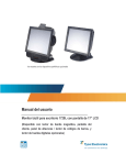
Copyright © 2000 by this company. No part of this publication may be reproduced, transmitted, transcribed, stored in a retrieval system or translated into any language or computer language, in any form or any means, electronic, mechanical, magnetic, optical, chemical, manual or otherwise, without the prior written permission of this company. DISCLAIMER 15” TFT LCD MONITOR User’s Manual This company makes no representations or warranties, either expressed or implied, with respect to the contents hereof and specifically disclaims any warranties, merchantability or fitness for any particular purpose. Further, this company reserves the right to revise this publication and to make changes from time to time in the contents hereof without obligation of this company to notify an person of such revision or changes. All brand or product names are trademarks or registered trademarks of their respective companies. SAFETY INSTRUCTION 1. The main plug isolates this equipment from the main supply. 2. Unplug this product from the wall outlet before cleaning. 3. Never push objects of any kind, or spill liquid of any kind into this product. 4. Do not attempt to service this product yourself. As opening or removing covers may expose you to dangerous voltage points or other risks. Refer all servicing to qualified service personnel. 5. The power supply cord serves as a power disconnect device for pluggable equipment, the socket outlet should be installed near the equipment and should be easily accessible. Federal Communications Commission (FCC Statement) This equipment has been tested and found to comply with the limits for a Class B digital device, pursuant to Part 15 of the FCC Rules. These limits are designed to provide reasonable protection against harmful interference in a residential installation. This equipment generates, uses, and can radiate radio frequency energy. If not installed in accordance with the instructions in this manual, harmful interference to radio communication may occur. However, there is no guarantee that interference will not occur in a particular installation. If this equipment dose cause interference to radio and television reception, which can be determined by turning the equipment off and on, the user is encouraged to try to correct the interference by one or more of the following measures: ● Re-orient or relocate the receiving antenna. ● Increase the space between the equipment and receiver. ● ● Connect the equipment into an outlet on a circuit different from the one which the receiver is connected. Consult the dealer or an experienced radio / TV technician for help. WARNING ● Use only shielded cables to connect I/O devices to this equipment. CAUTION ● ● Changes or modifications not expressly approved by the party responsible for compliance could void the user’s authority to operate the equipment. Use only RF shielded cable to connect this monitor to a computer device. Table Of Content CHAPTER 1 INTRODUCTION 1.1 Before Installing Your Monitor………………………….…………….…..5 1.2 Unpacking….…………………………………………….………………...5 1.3 About Your Monitor………………………………………..………………5 1.4 Precautions………………………………………………………………...6 1.5 ISO-13406-2 CLASS III USING INSTRUCTION…………………….…7 CHAPTER 2 TECHNICAL SPECIFICATION 2.1 Specification……………………………………………………………….8 2.2 Factory-Preset Modes………………..…………………………………12 2.3 Signal Connector Pin Assignments……………….……………………13 CHAPTER 3 INSTALLATION 3.1 Installing The Monitor……………………………...…………………….14 3.2 Touch Screen Software Installation(ELO / 3M)………………....…...15 3.3 Control Functions……………………………………………………..…16 CHAPTER 4 ADJUSTMENT 4.1 Adjusting The Monitor……………………………………………..…….17 4.2 Adjustment Procedure…………………………………………………..17 4.3 Auto-Adjustment…………………………………………………..……..17 4.4 On-Screen-Display Mode………………………………………...……..18 CHAPTER 5 CARD READER【OPTIONAL】 5.1 Dimensions……………………………………………………………….20 5.2 Card Reader Function…………………………………………………..21 CHAPTER 1 INTRODUCTION 1.4 ● 1.1 Before Installing Your Monitor ● Read this manual cover to cover. ● Pay attention to all warnings and cautions. ● Do not use computer components not recommended by the manufacturer. ● Unpacking - The monitor has a fragile glass screen. Never rub it with a hard, stiff object or tool for the panel is easily scratched. Your monitor is protected by one glass filter. - Every effort has been made to protect the screen, however the monitor is an extremely fragile product. ● Open the shipping carton and check the contents. If any items are missing or damaged, contact your dealer immediately. 1. 15” LCD Monitor. - Don’t let water or oil penetrate into the monitor. Even if drops are spilled and left for a long time, staining and discoloration may occur. 2. Power Cord. 3. Signal Cable. - Keep food particles and fingerprints away from the display area. 4. Adapter. 5. User’s Manual. 1.3 ● ● About Your Monitor This is a microprocessor-controlled, color monitor that uses a 15” TFT LCD panel. CLEANING - The display area is highly prone to scratching. Do not use ketone type material(ex. Acetone), ethyl alcohol, toluene, ethyl acid or methyl chloride to clean the screen. It might permanently damage the screen. Desirable cleaners are water, IPA(ISO Prophyl Alcohol)or Hexane. The package should include the following items: 6. Touch Parts Parcel.(CD. Signal Cable)【Option】 HANDLING - The monitor must be treated with caution and not be exposed to impact or shock. Do not attempt to service the monitor by yourself. If a problem occurs, contact the manufacturer’s authorized service center. 1.2 Precautions ● STORAGE - Do not store the monitor in temperatures higher than 60℃(140℉)or humidity higher than 85%. - Store in a dark place, keep away from sunlight and ultra violet(UV)radiation. - Air bubbles may develop within the glass screen, if this is not observed. Touch screen and anti-reflection strength glass is optional. 5 6 1.5 ISO-13406-2 CLASS III USING INSTRUCTION CHAPTER 2 TECHNICAL SPECIFICATION (For the monitor with internal touch screen) ● 2.1 ENGLISH Specification The application of this monitor is restricted to special controlled luminous environments. The screen surface tends to reflect annoying-light of lamp and sunlight. To avoid these reflections the monitor should not be positioned in front of a window or directed to luminaries. The monitor is in compliance with Reflection CLASS III according to ISO-13406-2. ● GERMAN Die Anwendung dieses Bildschirms auf speziel Kontrollierte Umgebungsbeleuchtungen eingeschr≅nkt. Die Bildschirmoberfl≅che neigt zu Strenden Spielungen von Lampen und Sonnenlicht. Um diese Refelxionen zu Vermeiden sollte der Monitor erfullt nur die Relelxionsklasse III nach ISO-13406-2. Overall Dimension(H×W×D):316×364×170 mm. Net Weight: 4 kgs. 4.4 kgs.(W/H Touch Screen) Shipping Weight: 6 kgs. 6.4 kgs.(W/H Touch Screen) Overall Dimension(H×W×D):318×364×190 mm. Net Weight: 4.5 kgs. 4.9 kgs.(W/H Touch Screen) Shipping Weight: 7 6.5 kgs. 6.9 kgs.(W/H Touch Screen) 8 Environmental Limits: Scan Frequencies: Horizontal 31.5 KHz to 60 KHz. Operating Temp. 0℃ to 40℃.(32℉ to 104℉) Vertical 56 Hz to 75 Hz. Storage Temp. -20℃ to 60℃.(-4℉ to 140℉) Operating Humidity 10% to 85% Without Condensation. Picture Tube: 15” TFT LCD Panel. Storage Humidity 10% to 85% Without Condensation. Power: Input Consumption Video Connector 100〜240 VAC.(Auto-Sensing) Frequency:50 Hz / 60 Hz. 27 Watts Maximum.(On) 3 Watts Maximum.(Without Adaptor) (Power Saving And Power Off) Agency Approval: EMI FCC-B and CE(EMC), BCIQ. Safety UL, CUL, CE(LVD). ※ Design and specifications are subject to change without prior notice. 15-Pin Mini D-Sub. Video Signals: Video Analog R.G.B 0.7Vp-p / 75Ω. Sync Separate, Positive Or Negative TTL. Display Data Channel: Compatibility VESA DDC 1/2B.(Option) Operations: User Controls On / Off Power Button, Menu, Up, Down, Enter. On Screen Display Brightness, Contrast, Auto Adjust, Phase, Clock, H-position, V-position, Sharpness, Color Temperature, Language, OSD Adjust, Recall. Control Type Digital. 9 10 Touch Screen: ● Style 5 Wires Analog Resistance. Surface Hardness PET≧3H. Active Area 307.1×231.1 mm. Keystroke Durability Driver CD ● 2.2 ELO Touch Meets Taber Abrasion Test (ASTH D1044)CS-10F wheel, 500g. DOS / WIN 9X, 2000, XP / WINDOWS NT / LINUX / I-MAC. 3M Touch Style 8 Wires Analog Resistance. Surface Hardness 4H Per ASTM D3363-92. Active Area 304.09×228.09 mm. Keystroke Durability 1,000,000 activations(Typical)at a single point with a 5/8” diameter silicone finger with a 350g load at 2 touches per second, using a 3M Touch Systems SC4 controller. Driver CD Windows 95, 98, ME, NT4, 2000, XP / XP Tablet PC Edition / Windows CE2.12, 3.0,.net / RedHat / Mandrake / iMac.OS9 / MS-DOS. 11 Factory-Preset Modes Table 1 shows standard settings that have been pre-adjusted at the factory for accurate display. These setting are stored in the monitor’s memory. Table 1 Mode US-TEXT VGA SVGA XGA Resolution H-Freq(KHz) V-Freq(Hz) 640×350 31.469 70.087 720×400 31.469 70.087 640×480 31.469 59.940 640×480 37.861 72.809 800×600 35.156 56.250 800×600 37.879 60.317 800×600 48.077 72.188 1024×768 48.363 60.004 1024×768 56.476 70.069 1024×768 57.524 72.000 1024×768 60.023 75.029 12 2.3 Signal Connector Pin Assignments CHAPTER 3 INSTALLATION 3.1 R.G.B Signal Connector Installing The Monitor The monitor is equipped with an auto-sensing power supply for voltage ranges from 100〜240 VAC, 50 / 60 Hz. Conforming the line voltage designation on the rear panel of the monitor. Pin 1 Analog Red Input Pin 2 Analog Green Input Pin 3 Analog Blue Input Pin 4 Ground Pin 5 Digital Ground Pin 6 Analog Red Ground Pin 7 Analog Green Ground 2. Plug one end of the 15-pin signal cable to the monitor and the other end to the video signal connector in the back of the system. Tighten the two screws of the cable connector on both ends.(Otherwise the screen will be abnormal and the LED light will be orange instead of green) Pin 8 Analog Blue Ground 3. Connect the power to the monitor through the AC / DC adapter. Pin 9 NC Pin 10 Sync Ground Pin 11 Ground Pin 12 SDA(DDC Data) Pin 13 H. Sync Pin 14 V. Sync Pin 15 SCL(DDC CLK) ● Follow These Steps To Install The Monitor: 1. Before you connect the cables, make sure that the monitor and the systems power switches are OFF. 4. Connect the power cord on the AC outlet. 13 5. Connect the 9-pin signal cable of Monitor to the PC series port.(COM1 / COM2 for RS232)(For touch screen only) 6. Connect the USB signal cable of monitor to the PC USB port.(For USB touch screen only) 14 6. Install the VESA stand: The rear cover is suitable for other stand or arm if they meet VESA standard 75×75 mm VESA Holes. 3.3 The Monitor control functions are located on the bottom side of the screen. They are shown in the figure below and described in the following paragraphs. ● The Control Key Description: 1. 3.2 ● Control Functions :Power Switch. 2. MENU:Active the on-screen-display function / Return menu / Exit. Touch Screen Software Installation(For Windows Platform) ELO Touch 1. Place the driving CD into CD-ROM driver. 3. :Move / Adjust down. 4. :Move / Adjust up. 5. ENTER. 2. Select an appropriate installation.(For Win 95, 98, 2000, XP or NT4.0, etc.) 3. Execute〝SETUP〞. 4. Select〝COM 1〞or〝COM 2〞.(Com 1 or Com 2 cannot be detected automatically) ● Description: 1. 5. Re-Start PC after the installation. 6. Execute〝3 PTS CAL〞to make position correction. Press button in each point 2〜3 seconds and loosen it then. ● :Power Switch. Use the power switch to turn the power ON or OFF. We recommend turning your system power on first, then the LCD monitor. 3M Touch 2. MENU. Press the Menu key to activate the On Screen Display mode.(It is a toggle key.)Press twice to turn off the OSD. After 20 sec idle time, the OSD screen will automatically turn off. 1. Place the driving CD into CD-ROM driver. 3. 2. Select an appropriate installation.(For Win 95, 98, 2000, XP or NT4.0, etc.) 3. Execute〝SETUP〞. 4. Re-Start PC after the installation. 5. Execute〝TOUCH KIT〞on desktop. 6. Execute〝ADD〞. 7. Execute〝4 PTS CAL〞to make position correction. (PS):Start that from the left-lower side anti-clockwise, press button in each point for 2〜3 seconds and loosen it then. 8. Advanced adjustment:To ensure the alignment accuracy and store into driving memories.(For 25 PTS CAL only) & :Select Key. The two keys have two sets of functions: 1 When OSD mode is activated(When〝MENU〞key is pressed), the two ○ keys are used to select the adjustment items. 2 When adjustment item is selected, the two keys are defined to decrease ○ or increase the values of each selected item. 4. ENTER. 1 When the light-bar move to the item, the key can be used to select it, ○ and ready to adjust. 2 At non-OSD mode pressing to execute Auto-Adjusting function, this ○ function will set the monitor display area to the optimal position. 9. Execute〝DRAW TEST〞to confirm the correction. 15 16 CHAPTER 4 ADJUSTMENT 4.1 4.4 On-Screen-Display Mode Adjusting The Monitor The LCD monitor is designed to work with a range of compatible adapters on the market. Due to the possible deviations between these adapters, you may need to make some adjustments to fir the monitor to the adapter used. BRIGHTNESS CONTRAST 4.2 AUTO ADJUST Adjustment Procedure 1. First, you must activate the OSD mode through pressing the MENU key, the symbols will show in the center of screen as below. Note:In the last paragraph, we will assume that you had already done this procedure and you only need an explanation on how to change the settings. 2. Use the & key to select the required adjustment item up or down. 3. Use ENTER key to select the item. 4. Use the & key to change the control value for optimum viewing. 5. After finishing all the settings, please press the MENU key, and then you’ll be back to Main Menu. If you press MENU key again, the setting will be saved into the monitor memory. If you want to discard the settings, just move to the 〝RECALL〞then press the〝ENTER〞key.(It will restore to the pre-defined values). 4.3 Auto-Adjustment PHASE CLOCK H-POSITION V-POSITION SHARPNESS ENGLISH COLOR TEMPERATURE FRENCH USER GERMAN 6500°k SPANISH 9300°k ITALIAN LANGUAGE PORTUGUESE OSD ADJUST OSD H-POSITION RECALL OSD V-POSITION OSD TIME 1. When OSD is not activated, using〝ENTER〞key to auto-adjust the display area to optimal display effects. RECALL 2. Sometimes this function can’t achieve the optimal effect, please follow the 〝Adjustment Procedure〞mentioned above. 17 18 ● Description: 1. BRIGHTNESS CHAPTER 5 CARD READER【OPTIONAL】 This field allows you to fine-tune the display brightness level. 2. CONTRAST This field allows you to adjust the display contrast level to accommodate the ambient lighting conditions of your working environment. 3. AUTO ADJUST This field allows you to adjust Phase and H-position & V-position & Clock automatically. 4. PHASE This field allows you to fine-tune the sampling phase according to the signal pixel. 5. CLOCK This field fine-tunes the sampling frequency, it will stretch or squeeze the display area horizontally. 6. H-POSITION This field allows you to adjust the display to the right or left. This field allows you to adjust the display up or down on the screen. 7. V-POSITION 8. SHARPNESS This field allows you to fine-tune the display sharpness level. 9. COLOR TEMP This field allows you to choose three types of color temperature 9300°K, 6500°K & user. If you chose the type of user, then you can adjust R. G. B. for your needs. 10. LANGUAGE This field allows you to choose six different languages- English, French, German, Spanish, Italian and Portuguese. 11. OSD ADJUST This field allows you to adjust OSD frame location, timeout, and reset OSD. 12. RECALL Recall the default value. 5.1 Dimensions Overall Dimension(H×W×D):316×405×170 mm Overall Dimension(H×W×D):318×405×190 mm 19 20 5.2 ● Card Reader Function Install Card Reader(Plug & Play) 1. Before you connect the cables, make sure that the monitor and the systems power switches are OFF. 2. Connect the PS2 signal cable of Monitor to the PC series port (PS/2)and other series the PS/2 keyboard. 21 15” TFT LCD MONITOR 0405 312-0276-201