1
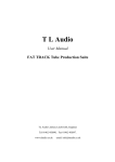
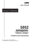
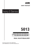
EQ-1 VALVE CLASSICS
by
TL Audio
User Manual
LIMITED EDITION VALVE EQUALISER
TL Audio Limited,
Sonic Touch,
Iceni Court,
Icknield Way,
Letchworth, SG6 1TN,
England.
Tel: +44(0)1462 680888, Fax: +44(0)1462 680999
E-Mail: [email protected]
www.tlaudio.co.uk
interstage
Phistersvej 31, 2900 Hellerup, Danmark
Telefon 3946 0000, fax 3946 0040
www.interstage.dk
- pro audio with a smile
INTRODUCTION
The TL Audio EQ-1 Dual Valve Equaliser combines classic valve techniques with low
noise solid state circuitry to produce a unit offering four bands of EQ on each of its
two channels. Both channels feature a line level input, plus a mic input with
switchable 48V phantom powering. Further flexibility is provided from a front panel
auxiliary input and Mono 8 Band operation mode. Typical applications include direct
recording to tape, instrument preamplifier, use as outboard EQ during mixdown, and
as a main stereo equaliser for monitoring and PA systems.
The block diagram of one of the channels is shown in fig.1. A solid state,
electronically balanced input amplifier is used, to achieve state of the art performance
with very low noise, low distortion and wide bandwidth. Two XLR input sockets are
provided per channel, for mic and line inputs. The mic input is suitable for low
impedance (150-600 ohm) microphones, with a gain control range of +16 to +60dB. A
front panel switch provides 48V phantom power to both channels. The line input has
an effective overall gain range of -10 to +35dB, allowing the valve stages to be fully
driven from line level signals in the range -20 to +20dBu. The line inputs and outputs
are also duplicated on unbalanced quarter-inch jack connectors.
A front panel mounted auxiliary jack socket allows direct access to the channel A
input, and is suitable for guitars, basses, samplers and keyboards etc.
An insertion point is provided immediately after the input stage, to allow a compressor
or other processor to be used as required. The insertion point is unbalanced, at a
nominal operating level of -2dBu.
The EQ section uses two twin triode valves per channel, arranged as a voltage
amplifier followed by three active EQ stages. The first EQ stage provides shelving LF
and HF filters, followed by individual stages for the low-mid and high-mid peaking
filters. Increasing the gain at the input stage allows the unique overdriven valve sound
to be gradually introduced. The EQ stages may be bypassed for easy A-B comparison.
The Mode switch allows selection of dual channel operation, with four EQ bands per
channel, or cascaded 8 band operation. In the mono 8 band mode, the channel A
mic/line input (or auxiliary input) is processed by the four band EQ of channel A,
followed by the four bands of channel B. The channel B gain control operates as a
master output level control in this mode.
A solid state, electronically balanced output stage completes the channel. All inputs
and outputs are also compatible with unbalanced signals. The outputs are switchable
for +4dBu or -10dBu nominal output level.
Please read this manual fully before installing or operating the EQ-1.
PRECAUTIONS
The EQ-1 requires very little installation, but like all electrical equipment, care must
be taken to ensure reliable, safe operation. The following points should always be
observed:
- All mains wiring should be installed and checked by a qualified
electrician,
- Ensure the correct operating voltage is selected on the rear panel
before connecting to the mains supply,
- Never operate the unit with any cover removed,
- Do not expose to rain or moisture, as this may present an electric
shock hazard,
- Replace the fuse with the correct type and rating only.
Warning: This equipment must be earthed.
INSTALLATION
AC Mains Supply.
The EQ-1 is fitted with an internationally approved 3 pin IEC connector. A mating
socket with power cord is provided with the unit, wired as follows:
Brown: Live.
Blue:
Neutral.
Green/Yellow: Earth (Ground).
All mains wiring should be performed by a qualified electrician with all power
switched off, and the earth connection must be used.
Before connecting the unit to the supply, check that the voltage selector switch on the
rear panel is correctly set. The unit may be set for 115V (accepting voltages in the
range 110V to 120V, 60Hz AC), or to 230V (for voltages in the range 220V to 240V,
50Hz AC). The fuse required is 20mm anti-surge. 1AT.
Warning:
attempted operation on the wrong voltage setting, or with an
incorrect fuse, will invalidate the warranty.
Audio Inputs.
Each channel has two female, 3 pin XLR connectors, for mic and line sources. Both
are compatible with either balanced or unbalanced signals, when the mating
connectors are appropriately wired:
Balanced inputs:
- Pin 1 = Ground (screen).
- Pin 2 = Signal Phase (“+” or “hot”).
- Pin 3 = Signal Non-Phase (“-” or “cold”).
Unbalanced inputs:
- Pin 1 = Ground (screen)
- Pin 2 = Signal Phase (“+” or “hot”).
- Pin 3 = Signal Ground
When using unbalanced signals, the signal ground may be obtained by linking pins 1
and 3 in the mating XLR connector. Good quality screened cable should be used,
particularly for microphone or low level sources, to prevent hum or noise pickup.
Unbalanced Line Inputs.
An unbalanced line level input is provided for each channel, on a 0.25” mono jack
socket. The mating plugs should be wired as follows:
- Tip =
Signal Phase (“+” or “hot”).
- Screen = Ground.
Auxiliary Input.
A 2 pin (mono) jack plug is required, which should be wired as follows:
- Tip =
Signal Phase (“+” or “hot”).
- Screen = Ground.
Insertion Points.
The insertion points are interfaced via a 3 pin, 0.25” switched jack socket on the rear
of the unit. The pin connections are:
- Sleeve = Ground,
- Tip = Send,
- Ring = Return.
The insertion point is unbalanced, and operates at a nominal level of -2dBu . If used
as an additional send only (e.g. as a send to a tape machine or monitor mixing desk),
the Tip and Ring should be wired together, to preserve the signal path through the
insertion point.
Outputs.
The outputs are via balanced, 3 pin male XLR connectors. The mating connectors
should be wired as follows:
- Pin 1 = Ground (screen),
- Pin 2 = Signal Phase (“+” or “hot”),
- Pin 3 = Signal Non-Phase (“-” or “cold”).
If an unbalanced output is required, pins 1 and 3 should both be connected to ground.
Nominal Output Level.
A switch on the rear panel allows the output to be matched to equipment at a nominal
operating level of +4dBu or -10dBu. Most professional equipment requires +4dBu
(approximately 1.2V rms), but some small mixing consoles, portable tape recorders
or domestic audio equipment require -10dBu (approximately 225mV rms). The
switch should be set to the position which results in the best signal to noise ratio,
whilst preserving sufficient headroom.
Unbalanced Outputs.
An unbalanced line output is provided for each channel, on a 0.25” mono jack socket.
- Tip =
Signal Phase (“+” or “hot”).
- Screen = Ground.
Ventilation.
The EQ-1 generates a small amount of heat internally, mainly due to the valve heaters.
This heat should be allowed to dissipate by convection through the grille in the front
panel, which must not be obstructed. Do not locate the EQ-1 where it will be subject
to external heating, for example, in the hot air flow from a power amplifier or on a
radiator.
The EQ-1 may be free standing, or mounted in a standard 19” rack.
Rear Panel.
The rear panel connectors are identified in fig.3.
OPERATION
Front Panel.
The front panel controls are identified in fig.2.
Input Stage.
Ensure that the correct input connector, mic or line, is being used and that the front
panel switch is set to the appropriate position. Note that both mic and line inputs may
be connected at the same time, but only one is selected.
+48V phantom power is available at the mic socket. The switch at the right hand side
of the front panel provides phantom power to both channels, signalled by a red LED.
CAUTION: Operation of the phantom power switch, or plugging a microphone in
with phantom power applied, may cause a click or thump in your loudspeakers. To
prevent this happening, ensure that the system gain is set to minimum (e.g. on your
mixing console fader or power amplifier), before operating the switch or plugging in a
microphone.
If the gain required is not known, set the control to minimum with the EQ by-passed,
and gradually increase the gain until the required output level is achieved.
Equalisation.
Before switching the EQ into circuit, it is advisable to set the cut/boost controls to
their centre, or flat, position. The EQ is brought into circuit with the “On” push
switch, signalled by a green LED.
Each channel has four bands of equalisation: shelving low frequency (LF), peaking
low-mid (LM), peaking high-mid (HM) and shelving high frequency (HF). Each band
has a continuously variable cut and boost control, plus a four position frequency
switch. The frequency switch sets the centre frequency of the LM and HM peaking
filters, and the corner frequency of the LF and HF shelving filters.
The Q of the mid band filters is approximately 0.5 (around 2 octaves), to cut or boost a
moderately broad bandwidth over a +/-12dB range. The shelving filters also provide
+/-12dB of cut and boost, over the full range of frequencies below the LF corner
frequency and above the HF corner frequency.
Used individually or in combination the filter bands allow comprehensive equalisation
of any audio signal, with the unique character of valve circuitry. Please note that the
signal is routed through the four valve stages only when the EQ “On” switch is
engaged. To benefit from the valve circuitry without EQ’ing the input signal, simply
engage the EQ ‘On’ switch, but leave the EQ set flat.
Typical response curves for each band are shown in the specification section of this
manual.
Auxiliary Input.
The front panel auxiliary input socket accepts low level signals from a guitar, bass
guitar, keyboard or high impedance microphone.
Plugging a jack plug into the auxiliary socket automatically disconnects the channel A
mic or line inputs, and replaces them with the aux input.
Mode Switch.
The Mode switch selects between dual channel operation, with four bands of EQ per
channel, and mono 8 band operation.
In mono 8 band mode, the input from channel A (or the aux input) is controlled by the
channel A gain control, and then processed by all 8 bands of EQ. The channel B gain
control functions as a master output level control in this mode (ideal for setting the
level going to tape or hard disc). Therefore the input signal should enter via the
channel A input, and the channel B output used as the overall mono output.
The channel A EQ In switch controls the first four bands of EQ, whilst the channel B
switch selects the second four bands. Note that the channel B line input is disabled in
this mode.
SPECIFICATIONS
Mic Input:
Electronically balanced, input impedance greater than
10Kohm, to suit 150-600 ohm microphones.
48V phantom power available, via switch with red LED.
Gain range +16 to +60dB.
Noise (EIN): -127dBu at maximum gain with a 150 ohm
termination, measured 22Hz-22KHz unweighted.
Maximum input level +10dBu.
3 pin female XLR connector.
Line Input:
Electronically balanced, unbalanced compatible, with input
impedance greater than 5Kohm.
Gain range -10dB to +35dB, suitable for nominal input levels
from -20dBu to +20dBu.
Maximum input level +30dBu.
3 pin female XLR connector.
Unbalanced Input:
Input impedance greater than 5Kohm.
Gain range -10dB to +35dB, suitable for nominal input levels
from -20dBu to +20dBu.
Maximum input level +30dBu.
2 pole 0.25” jack socket.
Auxiliary Input:
Input impedance 100Kohms, maximum gain 50dB.
Maximum input level 0dBu.
2 pole 0.25” jack socket.
Equalisation:
4 bands per channel, comprising:
LF +/- 12dB shelving, 4 switched frequencies at 60Hz,
120Hz, 250Hz and 500Hz.
LM +/- 12dB bandpass, 4 switched centre frequencies at
250Hz, 500Hz, 1KHz and 2K2Hz. Q approximately 0.5.
HM +/- 12dB bandpass, 4 switched centre frequencies at
1K5Hz, 2K2Hz, 3K6Hz and 5KHz. Q approximately 0.5.
HF +/- 12dB shelving, 4 switched frequencies at 2K2Hz,
5KHz, 8KHz and 12KHz.
EQ on switch, with green LED.
Outputs:
Electronically balanced, unbalanced compatible.
Rear panel selectable for +4dBu or -10dBu nominal level.
Output impedance less than 10 ohms.
Maximum level +26dBu into 10Kohms, +22dBu into 600
ohms (+4dBu nominal, balanced).
3 pin male XLR connector.
Unbalanced Outputs:
Output impedance 47 ohms.
Maximum level +20dBu into 10Kohms.
2 pole 0.25” jack socket.
Frequency Response:
20Hz to 20KHz, +0, -1dB, with EQ by-passed or flat.
Noise:
Noise floor -85dBu with line input at 0dB gain and EQ bypassed, -80dBu with EQ in and flat (+4dBu nominal level).
-95dBu and -90dBu respectively at -10dBu nominal level.
3 pin male XLR connector.
Dynamic Range:
105dB, EQ in and flat.
Mode Switch:
4 band dual channel or mono 8 band.
Channel B level control becomes master output level in mono
mode.
Distortion:
THD+N:
0.02% at 1KHz,
0.08%, 20Hz-20KHz.
IMD:
0.03%.
(All specified for line input at 0dBu and 0dB gain, EQ in and flat, after 10 minute
warm up time).
Insertion Points:
Unbalanced, switched 3 pin jack socket, tip = send,
ring = return.
Nominal level -2dBu.
Output impedance 47 ohms.
Return input impedance 10Kohms.
Power Requirements:
Rear panel selectable for 220-240V 50Hz or 110-120V 60Hz
operation.
Rear panel fuse 20mm, 1AT.
Power consumption 20VA typical.
Detachable 3 pin IEC connector, mating connector and cable
supplied.
Front panel On/Off switch with green LED.
Dimensions:
19” rack mounting, 2U high.
483mm wide x 88mm high x 205mm deep.
Weight:
4Kg.
In line with a policy of continuous development, the above specifications are subject to change without
notice.
SERVICE
Should the EQ-1 require service, it must be taken or posted to an authorised dealer.
Please retain the original packing for possible future use, and ensure the unit is
suitably protected during transit. The manufacturer cannot accept responsibility for
damage caused during transportation.
The EQ-1 is protected by a limited warranty for a period of one year from the date of
purchase. During this period, any faults due to defective materials or workmanship
will be repaired free of charge. The warranty excludes damage caused by deliberate or
accidental misuse, operation on the incorrect mains voltage, or without the correct type
and value of fuse fitted. It is the user’s responsibility to ensure fitness for purpose in
any particular application. The warranty is limited to the original purchase price of the
equipment, and excludes any consequential damage or loss.
Please record the following details:
Serial Number.............................
Date purchased...........................
Dealer.........................................
interstage
Phistersvej 31, 2900 Hellerup, Danmark
Telefon 3946 0000, fax 3946 0040
www.interstage.dk
- pro audio with a smile