1
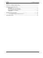
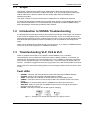
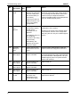
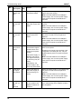
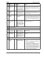
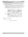
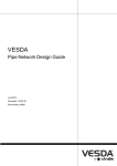
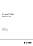
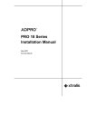
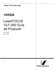
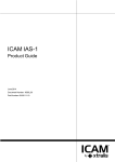
Troubleshooting
Guide
August 1, 2007
Document Number: 10257_04
Part Number: 30011
VESDA®
Troubleshooting Guide
Intellectual Property and Copyright
This document includes registered and unregistered trademarks. All trademarks displayed are the trademarks of their respective owners.
Your use of this document does not constitute or create a licence or any other right to use the name and/or trademark and/or label.
This document is subject to copyright owned by Xtralis AG (“Xtralis”). You agree not to copy, communicate to the public, adapt, distribute,
transfer, sell, modify or publish any contents of this document without the express prior written consent of Xtralis.
Disclaimer
The contents of this document is provided on an “as is” basis. No representation or warranty (either express or implied) is made as to the
completeness, accuracy or reliability of the contents of this document. The manufacturer reserves the right to change designs or
specifications without obligation and without further notice. Except as otherwise provided, all warranties, express or implied, including
without limitation any implied warranties of merchantability and fitness for a particular purpose are expressly excluded.
General Warning
This product must only be installed, configured and used strictly in accordance with the General Terms and Conditions, User Manual and
product documents available from Xtralis. All proper health and safety precautions must be taken during the installation, commissioning
and maintenance of the product. The system should not be connected to a power source until all the components have been installed.
Proper safety precautions must be taken during tests and maintenance of the products when these are still connected to the power source.
Failure to do so or tampering with the electronics inside the products can result in an electric shock causing injury or death and may cause
equipment damage. Xtralis is not responsible and cannot be held accountable for any liability that may arise due to improper use of the
equipment and/or failure to take proper precautions. Only persons trained through an Xtralis accredited training course can install, test and
maintain the system.
Liability
You agree to install, configure and use the products strictly in accordance with the User Manual and product documents available from
Xtralis.
Xtralis is not liable to you or any other person for incidental, indirect, or consequential loss, expense or damages of any kind including
without limitation, loss of business, loss of profits or loss of data arising out of your use of the products. Without limiting this general
disclaimer the following specific warnings and disclaimers also apply:
Fitness for Purpose
You agree that you have been provided with a reasonable opportunity to appraise the products and have made your own independent
assessment of the fitness or suitability of the products for your purpose. You acknowledge that you have not relied on any oral or written
information, representation or advice given by or on behalf of Xtralis or its representatives.
Total Liability
To the fullest extent permitted by law that any limitation or exclusion cannot apply, the total liability of Xtralis in relation to the products is
limited to:
(i) in the case of services, the cost of having the services supplied again; or
(ii) in the case of goods, the lowest cost of replacing the goods, acquiring equivalent goods or having the goods repaired.
Indemnification
You agree to fully indemnify and hold Xtralis harmless for any claim, cost, demand or damage (including legal costs on a full indemnity
basis) incurred or which may be incurred arising from your use of the products.
Miscellaneous
If any provision outlined above is found to be invalid or unenforceable by a court of law, such invalidity or unenforceability will not affect the
remainder which will continue in full force and effect. All rights not expressly granted are reserved.
Document Conventions
The following typographic conventions are used in this document.
Convention
Description
Bold
Used to denote: emphasis
Used for names of menus, menu options, toolbar buttons
Italics
Used to denote: references to other parts of this document or
other documents. Used for the result of an action.
The following icons are used in this document
Convention
Description
Caution: This icon is used to indicate that there is a danger to
equipment. The danger could be loss of data, physical damage,
or permanent corruption of configuration details.
Warning: This icon is used to indicate that there is a danger of
electric shock. This may lead to death or permanent injury.
iii
VESDA®
Troubleshooting Guide
Warning: This icon is used to indicate that there is a danger of
inhaling dangerous substances. This may lead to death or
permanent injury.
Contact Us
The Americas
+1 781 740 2223
Asia
+852 2297 2438
Australia and New Zealand
+61 3 9936 7000
Continental Europe
+41 55 285 99 99
UK and the Middle East
+44 1442 242 330
www.xtralis.com
Document Number: 10257_02
Part Number: 30011
iv
VESDA®
Troubleshooting Guide
Scope ................................................................................................................................................1
Introduction to VESDA Troubleshooting ......................................................................................1
Troubleshooting VLP, VLS & VLC .................................................................................................1
Fault LEDs ..............................................................................................................................1
Fault Finding with a LCD Programmer ....................................................................................2
Fault Finding with VESDA PC Software ..................................................................................2
Fault Reporting Through Relays .............................................................................................2
List of Faults ............................................................................................................................3
Troubleshooting LaserFOCUS .....................................................................................................16
VLF Troubleshooting with Instant Fault Finder .................................................................17
Internal Wiring Order ....................................................................................................................18
v
Troubleshooting Guide
vi
VESDA®
VESDA®
Troubleshooting Guide
1.1 Scope
The VESDA Troubleshooting Guide helps understand the faults that may arise from using
VESDA laser detectors and how to rectify these faults. If you are having problems with a pipe
network rather than a detector, please see the VESDA Pipe Network Installation and
Maintenance guides.
This guide is written for those involved with the maintenance of VESDA laser detectors.
It is assumed that people troubleshooting a VESDA laser detector are knowledgeable about the
local codes and standards. It is recommended that you attended accredited VESDA training
before attempting to troubleshoot problems with a detector.
1.2 Introduction to VESDA Troubleshooting
It is possible that occasionally a VESDA Laser System may indicate certain faults. It is normal for
a new system to highlight factory defaults and air flow faults. These are rectified as part of the
setup and commissioning process. Faults that may arise in the course of normal operations have
been identified and this guide provides information on how to troubleshoot and rectify those
faults.
Faults can be identified and rectified through a physical check, or by using the VESDA diagnostic
tools such as the LCD Programmer or VESDA PC Software.
1.3 Troubleshooting VLP, VLS & VLC
Faults on VESDA LaserPLUS (VLP), VESDA LaserSCANNER (VLS), or VESDA
LaserCOMPACT (VLC) systems are reported through the display modules. If connected, the
faults will also be reported on an LCD Programmer or on the VESDA PC Software. Information
on the fault is signalled through one of two fault relays - minor and urgent (by default relay K2
and K3). All faults are logged into the event log giving the time, date and the details of the fault.
When a fault occurs the relevant LED(s) will be lit on the display module. Faults can also be seen
in VSC.
Fault LEDs
•
•
•
•
•
•
•
URGENT - When lit, this LED indicates a serious fault requiring immediate attention
SYSTEM - When lit, this indicates a fault effecting the network
ZONE - If this LED is lit it indicates a VESDA Zone fault in the display module
POWER - If the GPI Function is used, and this LED is lit it indicates a fault in the power
supply
NETWORK - A communications fault on VESDAnet will cause this LED to be lit
AIRFLOW - Higher or lower than acceptable levels of air flow through the inlet pipe is
indicate.d when this LED is lit
FILTER - This LED is lit when the air filter requires changing
Figure 1 - Example of an airflow fault reported on a display module
1
Troubleshooting Guide
VESDA®
Fault Finding with a LCD Programmer
The LCD Programmer reports individual device faults. The faults are reported in the status
screen and are clearly identified with a “F” icon against the fault. Details of the faults can be
interrogated through the “status” option of the respective device. For further details please refer
to the VESDA LCD Programmer Product Guide.
Fault Finding with VESDA PC Software
The VESDA PC Software displays a fault on the active event list screen as these occur. The
active event list screen displays the date and time of the fault, the serial number of the device on
which the fault has occurred, the zone number, fault number, and a description of the fault. For
detailed information about a fault access the device tree menu, highlight the device, and select
device information. This will display the details of the fault.
VSC automatically stops displaying faults once the fault is cleared. When a fault occurs VSM4
displays the fault in the active event list screen and the status bar at the bottom of the screen. A
warning beeper is activated in the computer hosting VSM4 (provided the computer has a sound
card). The beeper will continue to sound until the fault is acknowledged.
For further details on PC Software please refer to the online help.
Fault Reporting Through Relays
VESDA devices are often interfaced with Fire Alarm Control Panels (FACPs) or building
management systems and may not be connected to display modules. In such instances the fault
relays signal the fault to the FACP or the building management system which then reports the
fault.
2
VESDA®
Troubleshooting Guide
List of Faults
The table below lists all the faults that may occur in a VESDA VLP, VLS or VLC. The table
contains the fault number, description, cause, and action required to fix the fault. The “LED Key”
column refers to the illustrations in the LED combinations for fault reporting on a display module
on page 15.
Fault
Description
LED
Key
0.
Aspirator
failed
1.
2.
No.
Cause
Action
A
The Detector’s
aspirator is not
working.
Call your VESDA support person to replace
the aspirator.
Power
supply
battery failed
B
There has been a loss
of battery power.
Replace battery.
Comms fault
on port A
C
There is a
communications fault
at port A.
•
•
•
•
3.
4.
Detector PIC
failure
Filter
removed
G
J
Check that the wiring is correct. Tighten
connections or repair any break in the
wiring. Refer to the detector manual for
details.
The location of the fault can be traced
because the devices on either side of the
loose connection or broken wire will both
report the fault.
The device that reported the fault can be
determined using the Status screen on
the LCD Programmer. For single detector
systems, check that the two VESDAnet
connectors on the termination card are
connected together. Also switch the
power off and check all internal
connections.
If a system is intentionally wired as an
open-ended loop this fault will continue to
occur unless the devices on each end of
the loop have been configured as openended using the programmer. Refer to the
LCD Programmer Guide or the VESDA
PC Software online Help.
The detector
processor board has
a hardware fault.
Call your VESDA support person to replace
the detector chassis.
The air filter has been
removed from the
detector.
The filter should be replaced.
This fault is generated when the device is
connected to the intelligent power supply
unit.
3
VESDA®
Troubleshooting Guide
Fault
Description
LED
Key
5.
Reference
detector loss
6.
No.
Cause
Action
I
The detector has not
received any
messages from its
configured reference
detector.
Check to see that the detector is configured
to look for the correct reference detector. If
this is OK, call your VESDA support person.
Power
supply DC
output
failure
F
The power supply has
a hardware failure.
Call your VESDA support person to repair or
replace the power supply.
7.
Software
fault found
G
The software is
malfunctioning.
Call your VESDA support person.
8.
Aspirator
speed
control
failure
D
The aspirator cannot
continue to run at set
speed, because:
•
Note: This fault relates to the VESDA intelligent power supply unit. For other power
supply units refer to respective manufacturer’s manuals
•
Set speed should be as indicated by
ASPIRE2.
Call your VESDA support person
The set rpm is outside
the operating range.
Either the aspirator or
the speed sensor
have failed.
9.
Comms fault
on Port B
C
There is a
communications fault
at port B.
•
•
•
•
4
Check that the wiring is correct. Tighten
connections or repair any break in the
wiring.
The location of the fault can be traced
because the devices on either side of the
loose connection or broken wire will both
report the fault.
The device that reported the fault can be
determined using the status screen on the
LCD Programmer. For single detector
systems, check that the two VESDAnet
connectors on the termination card are
connected together.
If a system is intentionally wired as an
open-ended loop this fault will continue to
occur unless the devices on each end of
the loop have been configured as openended using the programmer. Refer to the
LCD Programmer Guide or the VESDA
PC Software online Help
VESDA®
Troubleshooting Guide
Fault
Description
LED
Key
LED card on
display not
found
I
11.
Filter
approaching
capacity
12.
No.
Cause
Action
A display processor is
configured to have a
display card but
cannot find it (or viceversa). This may be
due to a failed
connector or an error
in the display
configuration.
Check that the display card is plugged in
then turn the power supply off and on.
E
The air filter is
approaching its
capacity. This is
based on the amount
of dust detected or
age of the filter.
The filter must be replaced and the filter
counter reset.
Zone setup
= factory
defaults
G
The common setup
area on the reporting
device has either not
been altered from the
factory defaults or has
reverted to the factory
defaults.
The fault must be cleared by calling the
administrator to select ‘Defaults OK’ from the
factory defaults menu.
13.
More than
one detector
in zone
G
An error in the system
configuration has
occurred and more
than one Detector has
been detected in the
zone.
This fault will recur every minute until the
fault is cleared. Ensure that each detector is
allocated a different VESDA Zone. If the fault
continues call your VESDA support person.
14.
Flow
sensors =
factory
defaults
I
The flow sensor
calibration area on
the detector has
either not been
altered from (or has
returned to) the
factory defaults.
Contact your VESDA support person to
return the detector for factory calibration
15.
AC mains
failure
F
The source supplying
AC power has failed,
or a fault with an
external PSU has
been signalled
through the GP Input
on the VESDA
detector.
Restore the AC power/batteries. Ensure the
GPI mains monitoring option has not been
incorrectly set. If the fault persists call your
VESDA support person.
10.
If the fault persists call your VESDA support
person to have the display card replaced.
5
VESDA®
Troubleshooting Guide
No.
16.
Fault
Description
LED
Key
Relays not
found
G
Cause
Action
A display or a
detector is configured
to have a relay card
but cannot find it (or
vice-versa).
Once the fault is corrected this fault can be
cleared by turning the power supply off and
on or pressing the reset button. Ensure the
number of relays configured match the
number of installed relays. If the fault persists
call your VESDA support person.
This may be due to a
failed connector or an
error in the display
configuration.
17.
No comms
from
detector
G
A display has not
received the regular
‘health check’
message from its
detector.
The detector may not
be configured
correctly or the wiring
may be faulty.
Call your Administrator to check the
configuration of the system.
Arrange for the wiring to be checked. Refer
to the detector manual. If the configuration
and wiring are OK, call your VESDA support
person.
Alternatively, the
detector in the zone
may have failed.
6
18.
Too many
displays in
zone
I
There may be more
than 20 devices in the
zone.
Call the system Administrator to alter the
number of devices configured in this zone.
19.
Flow sensor
failure pipe 4
D
The flow sensor on
pipe 4 has failed.
Check the flow sensor cable loom is properly
connected between the main chaise and the
pipe inlet manifold. If fault persists, call your
VESDA support person to replace the flow
sensor and manifold.
20.
Flow sensor
failure pipe 3
D
The flow sensor on
pipe 3 has failed.
Refer to fault 19
21.
Flow sensor
failure pipe 2
D
The flow sensor on
pipe 2 has failed.
Refer to fault 19
22.
Flow sensor
failure pipe 1
D
The flow sensor on
pipe 1 has failed.
Refer to fault 19
23.
Laser signal
too low
G
The detector’s preprocessor has
detected a loss of
smoke level signal.
Call your VESDA support person for a
replacement detector.
VESDA®
No.
24.
Troubleshooting Guide
Fault
Description
LED
Key
Cannot find
display/relay
G
Cause
Action
One of the displays in
a detector’s zone has
not sent its regular
health check message.
• If the display has been disconnected or a
new one installed use the rebuild list
option to clear the fault.
• If the display has failed, call your VESDA
support person to repair or replace the
display. Do not use rebuild list.
This will occur if the
display has failed or
has been disconnected.
25.
Comms on
Port A while
open-ended
C
Devices on the system can be configured as open-ended
on one port. If a
device such as an
LCD Programmer or a
HLI is attached to this
port this fault will be
reported. This fault
will also be reported if
there has been an
error in the system
configuration.
• If this fault is due to the temporary plugging in of an LCD Programmer or HLI, the
fault will be cleared when the device is
removed (If the devices have been programmed as non-latching). If however the
devices have been programmed as latching it is necessary to reset after the fault
condition is removed.
• Check that if there is communications on
both A and B ports, that open port should
be set to none.
26.
Comms on
Port B while
open-ended
C
Devices on the system can be configured as open-ended
on one port. If a
device such as an
LCD Programmer or
HLI is attached to this
port this fault will be
reported. This fault
will also be reported if
there has been an
error in the system
configuration.
See Fault 25
27.
AutoLearn
aborted
G
AutoLearn has been
aborted/interrupted
before the set time
After the cause of the interruption has been
determined, AutoLearn can be restarted.
28.
Scanner
option misconfigured
G
A non-Scanner display has been put into
a zone with a scanner
detector or vice versa
Check that all displays in a zone match the
detectors in that zone. That is, if the detector
in a zone has the scanner option all displays
for that zone must be scanner displays
The scanner valve
cable is disconnected
Ensure the scanner valve cable is connected
to the M.P.C.
7
VESDA®
Troubleshooting Guide
Fault
Description
LED
Key
29.
Manufacturer setup
corrupted
30.
Relay config
= factory
defaults
No.
8
Cause
Action
G
The manufacturer
setup on the reporting
device has either not
been altered from the
factory defaults or has
reverted to the factory
defaults.
Call your VESDA support person.
G
The part of the setup
that determines which
relays correspond to
which condition has
not been altered from
default settings, or
has reverted to the
defaults. This may be
because corruption of
the system has been
detected.
Refer to the LCD Programmer guide or the
VESDA PC Software online help for details
on how to accept the factory defaults. If the
problem persists, call your nearest VESDA
support person.
Note: Note: If this fault is due to a scanner
display’s zone having been changed, setting the relay assignment to that for the new
zone will clear the fault.
31.
Relay state
= factory
defaults
G
The part of the Relay
setup that determines the startup settings has not been
changed from the
default settings or has
reverted to these settings.
Refer to the LCD Programmer Guide or the
VESDA PC Software online Help for details
on how to accept the factory defaults. If the
problem persists, call your VESDA support
person.
32.
Detector
clocks not
synchronized
I
The internal clock on
all devices in the system are checked
daily. If the time on
any device has drifted
by more than one
minute this fault will
be reported.
The system Administrator should check the
time settings on the devices. Set the new
time as a global function. If this drift in time
continues to occur, call your VESDA support
person. This fault may occur on the first day
of use if the clocks are not synchronized
under the set date and time menu of the system all devices menu.
33.
User list =
factory
defaults
I
The user list has not
been changed from
the default settings or
has reverted to the
defaults. This may be
because corruption of
the system has been
detected.
The system Administrator is required to OK
the use of the defaults or to alter the user list.
Refer to the LCD Programmer Guide or the
VESDA PC Software online Help for details.
VESDA®
No.
34.
Troubleshooting Guide
Fault
Description
LED
Key
Detector
Setup = factory defaults
G
Cause
Action
The Detector setup
has not been
changed from the
default settings or has
reverted to the
defaults. This may be
because corruption of
the system has been
detected.
The system Administrator is required to OK
the use of the defaults. Refer to the LCD Programmer Guide or the VESDA PC Software
online Help. If the problem persists, call your
VESDA support person.
Note: Note that the detector alarm thresholds and other configurations are kept in the
detector setup area. If this fault occurs you
will have to reset all detector configuration
parameters.
35.
Programmer Setup =
factory
defaults
K
The programmer settings have not been
changed from the
default settings or has
reverted to the
defaults. This may be
because corruption of
the system has been
detected.
The system Administrator is required to OK
the use of the defaults or to alter the settings.
Refer to the LCD Programmer Guide. If the
problem persists, call your VESDA support
person.
36.
Event Log
corrupt
I
The detector event
log has been corrupted and has been
cleared.
If this fault persists call your VESDA support
person.
37.
Detector cal
= factory
defaults
G
The detector calibration has not been
changed from the
default settings or has
reverted to the
defaults. This may be
because the data has
been detected as
being corrupt.
Call your VESDA support person. Your system may not detect smoke correctly.
38.
Detector
EPROM failure
I
The detector data
storage area has not
been changed from
the default settings or
has reverted to the
defaults. This may be
because the data has
been detected as
being corrupt.
Refer to the LCD Programmer Guide or the
VESDA PC Software online Help for instructions on how to accept the factory defaults. If
this problem persists call your VESDA support person.
The airflow in the pipe
of the detector has
exceeded the ‘High
Urgent’ threshold.
This may be because
the aspirator setting
has been changed or
because there is a
break in the pipe.
If the aspirator setting has been changed the
system Administrator must be called to Normalize the air flow. If this does not rectify the
problem a contractor should examine and
repair any broken air sampling pipes.
39.
Urgent high
airflow pipe
4
A
Note that the filter life information is kept in
this storage area. If this fault occurs, the filter
life count will be set to zero.
9
VESDA®
Troubleshooting Guide
Fault
Description
LED
Key
40.
Minor high
airflow pipe
4
41.
42.
No.
Cause
Action
D
The airflow in the pipe
has exceeded the
‘High Minor’ threshold. This may be
because the aspirator setting has been
changed or because
there is a change in
the flow in the pipe.
If the aspirator setting has been changed the
system Administrator must be called to normalize the air flow. If the fault continues to
occur a contractor should be called to examine the pipe and repair any abnormalities.
Minor low
airflow pipe
4
D
The airflow in the pipe
has dropped below
the ‘Low Minor’
threshold. This may
be because the aspirator setting has been
changed or because
some sampling holes
are becoming
obstructed.
If the aspirator setting has been changed the
system Administrator must be called to Normalize the air flow. If the problem is not the
aspirator setting, call a contractor to clean
the sampling points. The sampling points
should be cleaned with a suit able implement.
Urgent low
air flow pipe
4
A
The airflow in the pipe
is below the ‘Low
Urgent’ threshold.
This may be because:
If the aspirator setting has been changed the
system Administrator must be called to normalize the air flow. If the aspirator setting has
not been changed call a contractor to check
for blockages in the pipe.
• the aspirator setting has been
changed; or
• there is a blockage
in the pipe; or
• all pipes may be
selected as “not in
use”
10
Check the number of pipes as selected “in
use”. Refer to the LCD Programmer Guide or
the VESDA PC Software online Help for
instructions on how to select pipes and Normalize the airflow.
43.
Urgent high
airflow pipe
3
A
Refer to Fault 39
Refer to Fault 39
44.
Minor high
airflow pipe
3
D
Refer to Fault 40
Refer to Fault 40
45.
Minor low
airflow pipe
3
D
Refer to Fault 41
Refer to Fault 41
46.
Urgent low
airflow pipe
3
A
Refer to fault 42
Refer to fault 42
47.
Urgent high
airflow pipe
2
A
Refer to Fault 39
Refer to Fault 39
VESDA®
Troubleshooting Guide
Fault
Description
LED
Key
Cause
Action
48.
Minor high
airflow pipe
2
D
Refer to Fault 40
Refer to Fault 40
49.
Minor low
airflow pipe
2
D
Refer to Fault 41
Refer to Fault 41
50.
Urgent low
airflow pipe
2
A
Refer to fault 42
Refer to fault 42
51.
Urgent high
airflow pipe
1
A
Refer to Fault 39
Refer to Fault 39
52.
Minor high
airflow pipe
1
D
Refer to Fault 40
Refer to Fault 40
53.
Minor low
airflow pipe
1
D
Refer to Fault 41
Refer to Fault 41
54.
Urgent low
airflow pipe
1
A
Refer to fault 42
Refer to fault 42
55.
Too many
power supplies.
I
More than one power
supply has been
detected in one power
zone.
Ensure “Power Supply” menu option is set to
Zone 0 if a VESDA Intelligent power supply is
being used.
No.
Note: This fault relates to the intelligent
power supply unit. For other power supply
units refer to respective manufacturer’s
manuals
56.
Clock failed
I
The real time clock is
not functioning properly.
Contact your VESDA support person to rectify the fault.
57.
Display
setup = factory defaults
I
The display is operating with the default
configuration.
The system Administrator is required to OK
the use of the defaults. Refer to the LCD Programmer Guide or the VESDA PC Software
online Help. If the problem persists, call your
VESDA support person.
58.
Too many
auto scans
in one week
I
There have been
more than 500 auto
scans have taken
place in a seven day
period.
To clear fault reset. Increase the scan
threshold by setting a higher alert threshold.
59.
Fault test
G
A fault test is currently
is progress.
This fault will cease when the fault test has
finished. You can clear the fault by prematurely ending the test.
11
VESDA®
Troubleshooting Guide
No.
60.
61.
62.
Fault
Description
LED
Key
Battery
charger failure.
F
Power Supply fuse failure.
B
Power Supply PIC failure.
B
Cause
Action
The power supply has
a hardware failure.
Call your VESDA support person to repair or
replace the power supply.
Note: This fault relates to the intelligent
power supply unit. For other power supply
units refer to respective manufacturer’s
manuals
The DC output fuse in
the power supply has
failed.
Call your VESDA support person to replace
the fuse.
The power supply
preprocessor has
failed.
Return the power supply to your VESDA support person so that it can be repaired or
replaced.
Note: This fault relates to the intelligent
power supply unit. For other power supply
units refer to respective manufacturer’s
manuals
Note: This fault relates to the intelligent
power supply unit. For other power supply
units refer to respective manufacturer’s
manuals
63.
No comms
from power
supply.
B
A detector has not
received the regular
‘health check’ message from its power
supply.
The power supply or
detector may not be
con figured correctly
or the wiring may be
faulty.
Call your Administrator to check the configuration of the system.
Arrange for the wiring to be checked. If the
configuration and wiring are OK, call your
VESDA support person to repair the power
supply.
Note: This fault relates to the intelligent
power supply unit. For other power supply
units refer to respective manufacturer’s
manuals
Alternatively, the
power supply in the
zone may have failed.
64.
65.
12
Power Supply output
relay failed.
Incompatible SW version
detected
B
K
One of the relays in
the power supply is
not functioning correctly.
Return the power supply to your VESDA support person so that it can be repaired or
replaced.
Some of the devices
on the system have
different versions of
software.
Call your VESDA support person to assist
you in determining which software versions
are compatible.
Note: This fault relates to the intelligent
power supply unit. For other power supply
units refer to respective manufacturer’s
manuals
VESDA®
Troubleshooting Guide
Fault
Description
LED
Key
66.
Status report
period too
short
67.
No.
Cause
Action
K
The parameter Min
Intvl has been set too
low when compared
with the number of
devices in the system.
You must call your VESDA support person to
reset the Min Intvl. Refer to the LCD Programmer Guide or the VESDA PC Software
online Help.
Network
delay too
short
K
The time allowed for a
device to send a message around the network is too short.
Arrange for your VESDA support person to
reset the Network Delay. Refer to the LCD
Programmer Guide or the VESDA PC Software online Help.
68.
HLI Setup =
factory
defaults
K
The HLI is operating
with the default configuration.
The system Administrator is required to OK
the use of the defaults or to alter the user list.
Refer to the LCD Programmer Guide or the
VESDA PC Software online Help. If the problem persists, call your VESDA support person.
69.
Ref Detector has reference
G
A Reference Detector is using another
Detector as a reference. Loops or chains
of Reference Detectors are not supported.
Call the system Administrator to reconfigure
the Reference Detector.
70.
Fault No. not in use
71.
Fault No. not in use
72.
LC Module
setup = factory defaults
G
The LC Module is
operating with the
default configuration.
The Administrator should okay the use of
default settings.
73.
Filter clogging warning
J
This fault will be generated if dust count
exceeds dust limit or
the filter Service Interval has expired.
Filter must be urgently replaced and reset filter count.
74.
Fault Rectified. Fault No. not in use
75.
Normalization has
failed
D
This fault will occur if
air normalization has
been unsuccessful
• Ensure at least one exhaust port is open
• Check the number of pipes selected as “in
use”
• Re-try air normalization. If fault persists
contact your Administrator
• If fault occurs at commissioning ensure
pipe has airflow of >20 liters per minute.
The fault may be caused by surplus air
from an area with a relatively high or low
pressure. Consider venting the exhaust
back into the protected area to balance
the pressure across the detector
13
VESDA®
Troubleshooting Guide
No.
76.
LED
Key
Filter
replaced but
not acknowledged
E
Cause
Action
The filter on a Detector has physically
been replaced but not
acknowledged in the
software.
Acknowledge filter change in software
Call your Administrator to check the positioning of the filter
Note: If a new filter has not been fitted DO
NOT reset the filter monitoring data
77.
Normalization in
progress
D
Normalization is currently in progress on
the detector.
This fault is generated as a reminder that the
detectors normalizing the air flow. This will
clear when normalization completes. If the
devices have been programmed as nonlatching, the fault will be cleared when the
device is removed. If however the devices
have been programmed as latching it is necessary to reset after the fault is generated
78.
No Sliding
Windows
Dial- Out
Dial String
I
This fault is generated
if the HLI attempts to
dial out without having a dial up number
configured in the
modem configuration
Ensure that a dial up number is con figured in
the dial-out HLI
79.
Both Dial
Numbers
failed during
a modem
dial out
I
This fault occurs if the
HLI fails to dial out
using either of the dial
up numbers configured in the modem
configuration
Ensure modem is powered up and connected
The Scanner Valve is
not fully open and
may be preventing
the free flow of sampled air.
Check inlet ports for obstruction. Perform
manual scan to check normal operation if
cleared.
The scanner valve is
stuck in the open
position. The sector
scan feature of the
LaserSCANNER
detector is non-functional
Check inlet ports for obstruction. Perform
manual scan to check normal operation if
cleared.
80.
Fault No. not in use
81.
Fault No. not in use
82.
Valve stuck
shut on Pipe
1 Urgent
83.
14
Fault
Description
Valve stuck
open on
Pipe 1 Minor
G
I
Ensure modem is configured to a baud rate
of 19200
Test the receiving station
Contact your VESDA support person for
technical support if fault persists.
Contact your VESDA support person for
technical support if fault persists.
84.
Valve stuck
shut on Pipe
2 Urgent
G
Refer to Fault 82
Refer to Fault 82
85.
Valve stuck
open on
Pipe 2 Minor
I
Refer to Fault 83
Refer to Fault 83
VESDA®
Troubleshooting Guide
Fault
Description
LED
Key
Cause
Action
86.
Valve stuck
shut on Pipe
3 Urgent
G
Refer to Fault 82
Refer to Fault 82
87.
Valve stuck
open on
Pipe 3 Minor
I
Refer to Fault 83
Refer to Fault 83
88.
Valve stuck
shut on Pipe
4 Urgent
G
Refer to Fault 82
Refer to Fault 82
89.
Valve stuck
open on
Pipe 4 Minor
I
Refer to Fault 83
Refer to Fault 83
No.
Table 1 - Troubleshooting Table
Table 2 below, illustrates the combination of illuminated LEDs on a display module representing
different type of faults. Each combination is represented with a letter (A to L) which corresponds
to the key column in the Troubleshooting Table on page 15.
The Zone, Network or System LEDs are illuminated to indicate where the fault has occurred. The
Urgent LED is illuminated in the event of a fault categorized as urgent (e.g. An Urgent High
Airflow Fault). Power, Airflow and Filter LEDs represent faults due to power supply, airflow or the
filter respectively.
LED Key
A
G
B
H
C
I
D
J
E
K
F
L
Table 2 - LED combinations for fault reporting on a display module
The X in indicates that a LED is lit.
15
Troubleshooting Guide
VESDA®
1.4 Troubleshooting LaserFOCUS
The Instant Fault Finder function is operated by pressing the Reset and Disable buttons together.
One or more segments of the Smoke Dial will be lit, indicating the fault by number. The table
below provides fault details and recommended actions.
16
VESDA®
Troubleshooting Guide
VLF Troubleshooting with Instant Fault Finder
The Instant Fault Finder function aids rapid diagnosis of faults.
Fault
Type
Explanation
Action
1
Filter
Air filter needs replacement
due to dust or smoke
contamination or has reached
the end of its life.
Replace the air filter with a new
unit remembering to reset the filter
fault.
2
Aspirator
Aspirator fault has occurred.
Initially replace the aspirator. If the
fault remains replace the VESDA
unit.
3
High flow
High flow fault present (urgent
or non-urgent). Flow readings
are above user set flow limits
or the detector maximum flow
Check the pipe network for
breakages. Also check the
suitability of the pipe network in
ASPIRE2.
4
Low flow
Low flow fault present (urgent
or non-urgent). Flow readings
are below user set flow limits
or the detector maximum flow
Check the pipe network for
blockages. Also check the
suitability of the pipe network in
ASPIRE2.
5
Not in use
6
External
Device/Power
Supply Unit
External equipment signaling a
fault via the General Purpose
Input.
Inspect the external device and
also check that the GPI is set to
the correct mode.
Also check that the EOL resistor is
correctly connected.
7
Interface card
Interface Card needs
replacement.
Replace the Interface Card.
8
Field wiring
General Purpose Input or
Interface Card wiring.
If no interface card is installed
check the GPI wiring for an open
circuit.
If an interface card is installed refer
to the card manual.
Refer to GPI section of the
LaserFOCUS Manual
9
AutoLearn fail
AutoLearn Smoke or Flow
failed.
Repeat AutoLearn Smoke or Flow
process. Inspect logs if repeated
failures occur. AutoLearn Flow will
fail if there is an airflow fault on the
detector. Fix airflow fault and restart AutoLearn
10
Detector
failure
A fault has occurred that
cannot be fixed.
Contact the supplier and replace
the detector.
Table 3 - Instant fault finder diagnosis
17
VESDA®
Troubleshooting Guide
1.5 Internal Wiring Order
When tracing for communication faults in a VESDAnet the internal connections depicted in
Wiring Configuration on page 18 will provide a useful guide to the exact location of the wiring or
communication fault. For example:
•
•
•
Where the fault is internal (e.g. a display on a VLP-002 is reporting a comms fault on port B
and the detector on port A) carefully check the internal grey cable looms for damage.
Where the fault is in the external/field wiring to terminal B, the comms fault will be reported
on Detector port B.
Where the fault is in the external/field wiring to terminal A, the comms fault may be reported
on a display, programmer or HLI depending on the particular configuration.
VESDAnet
Detector Termination
card
Terminal B
Terminal A
VESDAnet
Sockets
Programmer
Hand held
programmer
Detector
Processing Card
Terminal B
Terminal A
Detector
Display
HLI
Figure 2 - Wiring Configuration
18
VESDA®
Troubleshooting Guide
Index
A
E
AC mains fault .......................................
EPROM failure .......................................
5
Action to fix fault ................................... 3
AIRFLOW .............................................. 1
Aspirator failed ...................................... 3
Aspirator speed fault .............................. 4
auto scans fault ................................... 11
AutoLearn aborted ................................. 7
B
Battery charger failure ..........................
12
C
Can’t find display ...................................
7
Can’t find relay ...................................... 7
Cause of fault ........................................ 3
charger failure ..................................... 12
Clock failed ......................................... 11
clocks not synchronized ......................... 8
clogging warning ................................. 13
Comms fault ..................................... 3, 4
Contact Us ............................................ iv
Conventions ......................................... iii
9
Event Log corrupt .................................. 9
F
Fault Description....................................
3
Fault LEDs ............................................ 1
Fault No. ............................................... 3
Fault test ............................................. 11
FILTER.................................................. 1
Filter capacity ........................................ 5
Filter clogging fault .............................. 13
Filter fault............................................
14
Filter removed ....................................... 3
Flow sensor fault ............................... 5, 6
fuse failure .......................................... 12
H
HLI Setup ............................................
13
I
Incompatible SW version
...................... 12
Instant fault finder
D
Detector cal fault ...................................
9
Detector PIC failure ................................ 3
Detector Setup fault ............................... 9
Dial- Out ............................................. 14
Display setup fault ............................... 11
Troubleshooting guide .......................
17
L
Laser signal fault ...................................
6
LaserFOCUS faults ............................... 16
LC Module fault.................................... 13
LCD Programmer ...................................
2
LED card fault ........................................ 5
19
VESDA®
Troubleshooting Guide
LEDs ....................................................
1
Log corrupt ........................................... 9
Relays not found
................................... 6
S
M
Scanner fault .........................................
Minor high airflow ................................
10
Minor low airflow ................................. 10
modem dial out ................................... 14
More than one detector fault ................... 5
N
NETWORK ............................................
1
Network delay fault .............................. 13
No comms fault ..................................... 6
No comms from power supply............... 12
Normalization failed .............................
13
Normalization fault............................... 14
Numbers failed .................................... 14
P
2
PIC failure ....................................... 3, 12
Port A fault ........................................... 7
Port B fault ........................................... 7
POWER ................................................ 1
Power fault ....................................... 3, 4
Power Supply fault............................... 12
Power Supply output relay .................... 12
Programmer Setup fault ......................... 9
7
setup corrupted ..................................... 8
Sliding Windows .................................. 14
Software fault ........................................ 4
Status report fault ................................ 13
stuck open .......................................... 14
stuck shut ........................................... 14
SW version ......................................... 12
SYSTEM ............................................... 1
T
Too many auto scans ...........................
11
Too many displays ................................. 6
Too many power sup plies .................... 11
Troubleshooting VLC ............................. 1
Troubleshooting VLP ............................. 1
Troubleshooting VLS ............................. 1
PC Software ..........................................
R
13
Reference detector loss.......................... 4
Relay config fault................................... 8
Relay state fault..................................... 8
Relays .................................................. 2
U
URGENT ...............................................
1
Urgent high airflow ................................ 9
Urgent low air flow ............................... 10
User list fault ......................................... 8
V
Valve stuck open .................................
14
Valve stuck shut .................................. 14
Ref Detector fault.................................
20
Z
................................................... 1
Zone setup ............................................ 5
ZONE