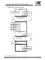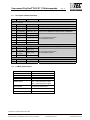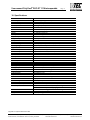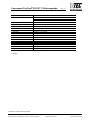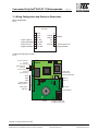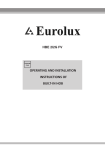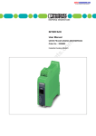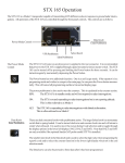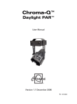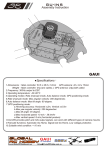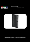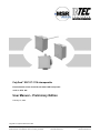
1
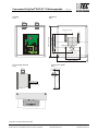
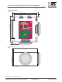
PolyGard DGC DT-1110-interoperable Electrochemical carbon monoxide transmitter LON interoperable serial no. DT-S 005 User Manual – Preliminary Edition February 01, 2006 Polygard® is a registered trademark of MSR Customer Services (858) 578-7887 & (888) GO INTEC Fax (858) 578-4633 & (888) FX INTEC INTEC Controls, 12700 Stowe Dr. Suite 110, Poway, CA 92064 www.inteccontrols.com Specification subject to change without notice. Printed in USA User manual PolyGard® DGC-DT 1110-interoperable Page 2 Electrochemical carbon monoxide transmitter LON interoperable 1 General Overview .................................................................................................................................... 3 2 Function description............................................................................................................................... 3 3 Installation................................................................................................................................................ 4 3.1 Assembly information..................................................................................................................... 4 3.2 Enclosure ....................................................................................................................................... 4 4 Electrical Connection.............................................................................................................................. 5 4.1 Instructions..................................................................................................................................... 5 4.2 Wiring connection .......................................................................................................................... 5 5 Start-up operation ................................................................................................................................... 6 5.1 Calibration ...................................................................................................................................... 6 5.2 Control span voltage calculation.................................................................................................... 7 6 Inspection and Service ........................................................................................................................... 7 6.1 Inspection....................................................................................................................................... 7 6.2 Calibration ...................................................................................................................................... 7 6.3 Replacing of the sensor element ................................................................................................... 7 7 Troubleshooting ...................................................................................................................................... 7 7.1 Diagnostics of the transmitter ........................................................................................................ 7 8 Cross-sensitivity Data............................................................................................................................. 8 9 LonMark Object and Network Variables ............................................................................................... 9 9.1 Description of Network Variables................................................................................................. 10 9.2 LonMark product details............................................................................................................... 10 10 Specifications ........................................................................................................................................ 11 11 Wiring Configuration and Enclosure Dimensions ............................................................................. 13 12 Notes and General Information............................................................................................................ 16 12.1 Intended product application........................................................................................................ 16 12.2 Installers' responsibilities............................................................................................................. 16 12.3 Maintenance ................................................................................................................................ 16 12.4 Limited warranty........................................................................................................................... 16 12.5 Return instructions ....................................................................................................................... 16 Polygard® is a registered trademark of MSR Customer Services (858) 578-7887 & (888) GO INTEC Fax (858) 578-4633 & (888) FX INTEC INTEC Controls, 12700 Stowe Dr. Suite 110, Poway, CA 92064 www.inteccontrols.com Specification subject to change without notice. Printed in USA User manual PolyGard® DGC-DT 1110-interoperable Page 3 Electrochemical carbon monoxide transmitter with LON interoperable Interface 1 General Overview The PolyGardCO digital gas transmitter is used for detection of carbon monoxide in the ambient air to monitor the presence of carbon monoxide gas. 2 Function description The sensor portion of the PolyGard£ DT-1110 digital gas transmitter is a micro-fuel cell, which is completely sealed. The measurement is a gas-in-liquid chemical reaction rather than a surface area measurement. With no surface area to coat, this sensor retains its sensitivity to carbon monoxide even after prolonged exposure to clean air. The cell consists of a diffusion barrier, O-ring seal, electrolyte reservoir and two electrodes, sensing and counter. The target gas, carbon monoxide, enters the cell through a diffusion barrier. The chemical process of the measurement is one of oxidation where one molecule of the target gas is exchanged for one molecule of oxygen. The reaction drives the oxygen molecule to the counter electrode, generating a DC microampere signal between the sensing and counter electrodes. The amount of electrons produced by the reaction is directly proportional to the amount of gas present and measuring the current flowing through the external circuit is a basic gas monitor. The integrated amplifier circuit and ADC converts this DC microampere signal to a digital signal with a ppm range. For the interoperable communication this value is written in the Standard Network Variable SNVT nvo01_TOX. Most sensors produce a small amount of baseline current in clean air. This is adjusted out with the zero potentiometer on the transmitter. This oxidation at the electrodes causes wear of the sensor. Typical life for this sensor is approximately five years in normal operation. This will vary somewhat from sensor to sensor, with some working lifetimes less than five years and some greater than five years. This wear also changes the characteristics of the sensor, requiring periodic recalibration. It is recommended that the sensor accuracy be verified every six months and recalibrated with the gain 1 potentiometer as necessary. The DGC- DT 1110 has (1) 4 to 20 mA Input for connection of (1) analog gas Transmitter with 4 to 20 mA Output. The signal is available in the SNVT nvo02_COMB. (4 mA = 0 %, 20 mA = 100%) Polygard® is a registered trademark of MSR Customer Services (858) 578-7887 & (888) GO INTEC Fax (858) 578-4633 & (888) FX INTEC INTEC Controls, 12700 Stowe Dr. Suite 110, Poway, CA 92064 www.inteccontrols.com Specification subject to change without notice. Printed in USA User manual PolyGard® DGC-DT 1110-interoperable 3 Page 4 Installation Note: x Avoid any force (e.g. by thumb) during operation or installation on the sensor element. This could destroy the element. x Electronics can be destroyed through static electricity. Therefore, do not work on the equipment without a wrist strap connected to earth ground or standing on conductive floor. 3.1 Assembly information x The specific weight of carbon monoxide is almost the same as that of air (factor 0.967). x Location of the sensor must conform to the layout of the area being monitored. x Disregard the ventilation ratio! Do not mount sensor in the center of the airflow. In larger rooms, it might be necessary to install two or more transmitters where there is not adequate air movement. Do not mount in corners or directly in front of air inlets (e.g. doors, windows, open ramps, dampers, etc.). In areas with undefined air movement, it might be necessary to distribute several transmitters in a vertical and horizontal direction over the whole area to be monitored. x Avoid locations where water, oil etc. may influence proper operation and where mechanical damage can be possible. x Mounting height is five feet above floor (max. 6 feet), (1.5 - 1.8 m). x Provide adequate space around sensor for maintenance and calibration work. x Duct model mounting: Mount only in a straight section of duct with minimum air vortex. Keep a minimum distance of 3.5 feet (1m) from any curve or obstacle. Mount only in a duct system with a maximum air velocity of 2000 ft/min or less. Mounting must be made so that the airflow is in line with probe openings. (see Fig. 5 page 14) 3.2 Enclosure x Un-screw cover of enclosure. x Carefully unplug the basic PCB mounted on fixed terminal blocks. x Screw the base vertically on wall or on a single gang electrical box. (see Fig. 4, page 14). x For duct model mounting: Cut a hole in the duct and install the probe in the hole. (see Fig. 6, page 14) Screw the housing to the duct using the mounting holes inside enclosure. x Plug in the basic PCB and replace the cover after wiring connection is completed (see Fig. 1 page 13). Polygard® is a registered trademark of MSR Customer Services (858) 578-7887 & (888) GO INTEC Fax (858) 578-4633 & (888) FX INTEC INTEC Controls, 12700 Stowe Dr. Suite 110, Poway, CA 92064 www.inteccontrols.com Specification subject to change without notice. Printed in USA User manual PolyGard® DGC-DT 1110-interoperable 4 4.1 Page 5 Electrical Connection Instructions Note: Electrostatic discharge (ESD) may damage electronic components. During wiring, open the cover only when completely grounded via grounding strap or standing on conductive floor. x Connections should be made without any power applied to conductors. x Installation of the electrical wiring should be according to the connection diagram and only performed by a trained specialist. x Cable Type LON: see “Wiring Guidelines for Twisted Pair LonWorks Networks” from Echelon. x Cable Type Power: No recommendation (Generally use one cable for LON and Power) x Cable insulation: Since the PCB mounts on top of the wiring terminations, it is important to ensure that the wire shields or any bare wires do not short to the PCB! Terminal strip X4 Connector 1 Connector 2 Connector 3 Connector 4 Connector 5, 6, 7 Power supply Input (+) 24 VDC, 10 – 28 VDC 0 VDC Input Power supply Output (+) for analog Tansmitter ( = Power supply Input – 0.7 V) 0 VDC Output Shield Terminal strip X5: Connector 1 Connector 2 Connector 3, 4 Connector 5 4.2 LON Bus (A) LON Bus (B) NC 4 to 20 mA Input from analog Transmitter Wiring connection x Unscrew cover of enclosure. x Unplug basic PCB from terminal blocks. For single gang electrical box mounting: x Pull through cable via hole in base; connect cable leads on terminal block X4 and X5. (see Fig. 1 page 13) For surface mounting (cable entry always from the top) and also for duct mounting: x Remove cover to access cable. x Connect cable leads on terminal block X4 and X5. x Plug the PCB on fixed terminal blocks on base. x Screw cover on base. Polygard® is a registered trademark of MSR Customer Services (858) 578-7887 & (888) GO INTEC Fax (858) 578-4633 & (888) FX INTEC INTEC Controls, 12700 Stowe Dr. Suite 110, Poway, CA 92064 www.inteccontrols.com Specification subject to change without notice. Printed in USA User manual PolyGard® DGC-DT 1110-interoperable 5 Page 6 Start-up operation Only trained technicians should perform the following: x Check mounting location. x Check airflow direction for duct mounting. x Check power voltage. x Check PCB DT-S05 for proper mounting at X4 and X5. x Check for correct sensor element (Eco Sure) at terminal PCB DT-S05. x Commissioning and Binding of the DGC- DT with LONMaker or other Binding Tool. x Verify transmitter operation (sensor/transmitter was factory calibrated). 5.1 Calibration Note: Please observe proper handling procedures for test gas bottles! Note: If calibration is necessary, the sensor element must be powered and be fully stabilized for at least 1 hour. Required instruments to calibrate the transmitter: x Test gas bottle with synthetic air. x Test gas bottle with 150 - 250 ppm CO. x Gas pressure regulator with flow meter to control the gas flow to 150 ml/min. x Sensor head calibration adapter with tubing. x Digital voltmeter with range 0 – 10 VDC, accuracy 1% and a small screwdriver. Zero adjustment Zero-point calibration (4 mA): (After sensor warm-up) x Connect digital voltmeter to test pins X13 – and + (with a range selected that will display 10 VDC max.). x Connect the calibration adapter to sensor element. x Apply sensor element zero calibration gas, (150 ml/min; 14.5 psi ± 10%), or other clean air source. x Wait two minutes until the signal is stable, adjust signal with zero potentiometer ”Zero” until the signal is 2450 mV ± 3 mV and stable. x Remove calibration adapter carefully by turning lightly. Span adjustment Note: CO calibration gas is toxic, never inhale the gas! Symptoms: Dizziness, headache and nausea. Procedure if exposed: Bring into fresh air at once, consult doctor. x Connect calibration adapter to the sensor element. x Apply sensor element span calibration gas (150 – 250 ppm CO), (150 ml/min; 14.5 psi ± 10%). x Wait two minutes until the signal is stable, adjust signal with span potentiometer ”Gain1” until the signal reads the appropriate mVDC (± 3mV, see calculation for control span voltage 5.2) and is stable. x Remove calibration adapter with a careful light turn. Inspect the seating of the sensor element! Polygard® is a registered trademark of MSR Customer Services (858) 578-7887 & (888) GO INTEC Fax (858) 578-4633 & (888) FX INTEC INTEC Controls, 12700 Stowe Dr. Suite 110, Poway, CA 92064 www.inteccontrols.com Specification subject to change without notice. Printed in USA User manual PolyGard® DGC-DT 1110-interoperable 5.2 Page 7 Control span voltage calculation 2450 (mV) – [8 (mV) x test gas concentration (ppm)] Example Test gas concentration Control voltage 220 ppm CO 690 mV 2450 (mV) – [8 (mV) x 220 (ppm)] = 6 6.1 690 mV Inspection and Service Inspection Inspection and service of the transmitters should be done by a trained technician and executed on a periodic interval. It is recommended that the sensor operation be verified at least every six months. 6.2 Calibration (See part 5.1 and 5.2) x Service at periodic intervals is to be decided by the person responsible for the gas detection system. x If span calibration voltage < 40% of the calculated Control span voltage, when applying Carbon Monoxide calibrate gas in air, then the sensor element has to be replaced. After the sensor element has been replaced a calibration is required. 6.3 Replacing of the sensor element Static electricity (see section 4.1). Sensor should always be installed without power applied: x Unplug basic PCB DT-S05 carefully from the terminal blocks on the base. x Unplug old sensor element out from the PCB DT-S05. x Take new sensor element out of original packing. x Plug sensor element in the PCB DT-S05. x Plug the PCB DT-S05 in terminal block X4, X5 carefully. x After sensor warm-up, Calibrate see section 5.1) 7 7.1 Troubleshooting Diagnostics of the transmitter Trouble Reason Solution Power LED not light up Measure power voltage terminal block X4 terminal 1 (+) and 2 for 10 – 28 VDC Basic PCB DT-S05 X4 and X5 Plug in the basic PCB DT-S05 into X4 not plugged in correctly and X5 correctly Service LED flash No Application load Power not applied Load Application File Polygard® is a registered trademark of MSR Customer Services (858) 578-7887 & (888) GO INTEC Fax (858) 578-4633 & (888) FX INTEC INTEC Controls, 12700 Stowe Dr. Suite 110, Poway, CA 92064 www.inteccontrols.com Specification subject to change without notice. Printed in USA User manual PolyGard® DGC-DT 1110-interoperable 8 Page 8 Cross-sensitivity Data This table shows the typical response to be expected from the sensor when exposed to the following gases. Gas Acetone Chemical mark Gas concentration Exposure Time (mins) (CH3)CO(CH3) 1000 ppm 5 0 ppm Tolerance ppm CO Acetylene C2H2 40 ppm 5 80 ppm Ammonia NH3 100 ppm 5 0 ppm Carbon Dioxide CO2 5000 ppm 5 0 ppm Chlorine CL2 2 ppm 5 0 ppm Ethanol C2H5OH 2000 ppm 30 5 ppm H2 100 ppm 5 20 ppm H 2S 25 ppm 5 0 ppm C3H7OH 200 ppm 120 0 ppm Nitric oxide NO 50 ppm 5 8 ppm Nitrogen dioxide NO2 50 ppm 900 1 ppm Sulphur dioxide SO2 50 ppm 600 < 0.5 ppm Hydrogen Hydrogen sulphide Iso Propanol Polygard® is a registered trademark of MSR Customer Services (858) 578-7887 & (888) GO INTEC Fax (858) 578-4633 & (888) FX INTEC INTEC Controls, 12700 Stowe Dr. Suite 110, Poway, CA 92064 www.inteccontrols.com Specification subject to change without notice. Printed in USA User manual PolyGard® DGC-DT 1110-interoperable 9 Page 9 LonMark Object and Network Variables Node Object#0 Type # 0 nvi00Request SNVT_obj_request nvo00Status SNVT_obj_status nvo_Alarm SNVT_alarm CONFIGURATION PROPERTIES nc52 -Min Send Time nc1 – Gas Type Tuning Manufacturer section nvi_Com SNVT_str_int nvi_Thresh SNVT_str_int nvi_Param SNVT_str_int nvi_Test SNVT_count Gas Sensor INP#1 Object#1 Type#1 nvo01_TOX SNVT_ppm CONFIGURATION PROPERTY nc26 – Generic Offset nc31 – Generic Gain Manufacturer Section nvi_ENABLE SNVT_switch Gas Sensor 4-20mA INP#2 Object#2 Type#1 nvo02_TOX SNVT_ppm nvo02_COMB SNVT_lev_percent Polygard® is a registered trademark of MSR Customer Services (858) 578-7887 & (888) GO INTEC Fax (858) 578-4633 & (888) FX INTEC INTEC Controls, 12700 Stowe Dr. Suite 110, Poway, CA 92064 www.inteccontrols.com Specification subject to change without notice. Printed in USA User manual PolyGard® DGC-DT 1110-interoperable 9.1 Page 10 Description of Network Variables Index Network Typ Description Object #0 Type #0 0 nviRequest SNVT_obj_request To request modes for objects within this node. 1 nvoStatus SNVT_obj_status To report the status of objects on this node 2 SNVT_alarm Only for DGC-system function, no interoperable function SNVT-time_sec Min Send Time (Min Value =1) Must set on each Node!! 4 nvo_Alarm nc52 (nci-minSEND) nc1 5 nvi_Com SNVT_str_int 6 nvi_Thresh SNVT_str_int 7 nvi_Param SNVT_str_int 8 nvi_Test SNVT_count 3 Only for DGC-system function, no interoperable function Object #1 Type #1 (Value ppm) 9 nvo01_TOX nc26 (nci_OFFSET) nc31 (nci_GAIN) nvi_ENABLE 10 11 12 SNVT_ppm Value CO gas Concentration (ppm) SNVT_ppm SNVT_muldiv Only for DGC-system function, No interoperable function SNVT_switch Object #2 Type #2 (Value external Input) (%) 13 nvo02_TOX SNVT_ppm 14 nvo02_COMB SNVT_lev_percent Value (%) Input 4- 20 mA (4 mA = 0%, 20 mA = 100%) 9.2 Only for DGC-system function, no interoperable function LonMark product details Product data sheet (PDF) PolyGard Digital Transmitter DT Device category Gas concentration Communication TP/FT-10 LonMark version Standard programm ID 3.2 0000 – Node object 0001 – Open loop sensor object 0002 – Open loop sensor object 8000230A50060402.zip XIF (External interface file) 8 00023 0A50 06 04 02 Certificates TÜV, VDI 2053 LonMark object Download files Polygard® is a registered trademark of MSR Customer Services (858) 578-7887 & (888) GO INTEC Fax (858) 578-4633 & (888) FX INTEC INTEC Controls, 12700 Stowe Dr. Suite 110, Poway, CA 92064 www.inteccontrols.com Specification subject to change without notice. Printed in USA User manual PolyGard® DGC-DT 1110-interoperable Page 11 10 Specifications Electrical Power supply: Power consumption: Power consumption ext. Transmitter RFI/EMI protection Sensor Performance Gas detected Sensor element Range Stability & resolution Repeatability Long term output drift Response time Sensor life expectancy Sensor coverage Mounting height Type of Control SNVT nvo01_TOX SNVT nvo02_COMB. Communication Processor Clock speed Transceiver Network speed Network compatibility Operating Environment Working temperature Storage temperature Humidity - Continuous - Intermittend Pressure range Physical characteristics Enclosure material Enclosure color Wall mounting Installation Dimensions (HxWxD) Cable entry Wire connection Wire size Weight 10-28 VDC (polarity protected) 28 mA, (0.7 VA), max. 100 mA, (3.0 VA), max. 5.0 W @1 ft. (0.31 m) radiated Carbon monoxide (CO) Electrochemical, diffusion 0 – 300 ppm factory set ± 3 % of reading < ± 3 % of reading ± 5% /year t90 d 50 sec. 5 year, normal operating environment 5,000 sq.ft., (465 m2), to10,000 sq.ft. (930 m2) under “ideal conditions” 5 to 6 ft. (1.5 to 1.8 m) above floor Proportional, 0 – 300 ppm CO Proportional, 0 – 100 % ( 4 – 20 mA) Neuron 3150 10 MHz FTT 10A 78 kBits/sec TP/FT-10 14 °F to 122 °F (-10 °C to + 50 °C) 41 °F to 86 °F ( 5 °C to + 30 °C) 15 to 90% RH non-condensing 0 to 99% RH non-condensing Atmospheric ±10% Galvanized Steel w/zinc coating, corrosion resistant Light gray NEMA1 (IP 42) Wall (surface) mounted or single gang electrical box 5.59 x 5.59 x 2.48 in. (142 x 142 x 63 mm) 2 hole for ½ in. conduit for wall (surface) mounting, and 1 hole on back side of base plate for single gang electrical box mounting Terminal blocks, screw type for lead wire Min. 24 AWG (0.25 mm2), max. 14 AWG (2.5 mm2) 0.7 Ibs. ( 0.3 kg ) Polygard® is a registered trademark of MSR Customer Services (858) 578-7887 & (888) GO INTEC Fax (858) 578-4633 & (888) FX INTEC INTEC Controls, 12700 Stowe Dr. Suite 110, Poway, CA 92064 www.inteccontrols.com Specification subject to change without notice. Printed in USA User manual PolyGard® DGC-DT 1110-interoperable Page 12 Approvals/Listings Warranty Opions Enclosures Duct mounted - w/probe - cable entry Wall mounted - material - color Dimensions (HxWxD) Heater, built-in Power supply Power consumption For ambient temperature Thermostatic control CE VDI 2053 * EMV-compliance 89/336/EWG Two years material and workmanship NEMA 3 (IP 44) 7/8 in. (22 mm) diameter and 7.16 in. (182 mm) length 1 hole for ½ in. conduit NEMA 4X w/splash guard (IP 65) ABS UL94V0 Light gray 4.8 x 4.72 x 3.42 in. (122 x 120 x 87 mm) 24 VAC ± 5%, 50/60 Hz 1.0 A (24 VAC), max. - 40 °F (-40 °C) 32 °F (0 °C) ± 5 °F (3 °C) * Pending Polygard® is a registered trademark of MSR Customer Services (858) 578-7887 & (888) GO INTEC Fax (858) 578-4633 & (888) FX INTEC INTEC Controls, 12700 Stowe Dr. Suite 110, Poway, CA 92064 www.inteccontrols.com Specification subject to change without notice. Printed in USA User manual PolyGard® DGC-DT 1110-interoperable Page 13 11 Wiring Configuration and Enclosure Dimensions Wiring Configuration Fig. 1 Transmitter DT-1100 X4 7 shield 6 shield 5 shield Power output for 4 < 0 VDC Analog transmitter 3 < 24 VDC Power input for 2 > 0 VDC Digital transmitter 1 > 24 VDC LON_B LON_A DI DI 4-20 mA X5 1 LON-Bus 2 3 4 5 4 - 20 mA signal from analog transmitter connection Printed circuit board DGC DT-S05 Fig. 2 PCB Terminal resistence 107 Ohm (Line Topology) CPG/w Without Terminal resistence Terminal resistence 52.5 Ohm (Free Topology) Power LED Service LED Service Pushbutton shield 7 shield 6 1 LON_B shield 5 2 LON_A Power Output analog Transm. + 4 3 Power Input DGC-DT + 2 1 4 5 4..20 mA X5 1 Control Signal X4 Sensor Connect Socket only for DGC- Service Tool Polygard® is a registered trademark of MSR Customer Services (858) 578-7887 & (888) GO INTEC Fax (858) 578-4633 & (888) FX INTEC INTEC Controls, 12700 Stowe Dr. Suite 110, Poway, CA 92064 www.inteccontrols.com Specification subject to change without notice. Printed in USA User manual PolyGard® DGC-DT 1110-interoperable Assembly Fig. 3 Page 14 Dimensions Fig. 4 7 1 2.48 in. (63 mm) Cable entry 0.83 in. (21 mm) 5.59 in. (142 mm) Hole for mounting 3.3 in. (84 mm) 5 1 X5 X4 d=0.16 in. (4 mm) D=0.88 in. (22,5 mm) D=0.16 in. (4 mm) 1 CPG/w PCB 2.75 in. (70 mm) 5.59 in. (142 mm) Duct mounting enclosure Fig. 5 Cutout for duct model Fig. 6 2.48 in. (63 mm) 0.83 in. (21 mm) D=0.16 in. (4 mm) D=0.88 in. (22.5 mm) 7.16 in. (182 mm) D=0.16 in. (4 mm) Polygard® is a registered trademark of MSR Customer Services (858) 578-7887 & (888) GO INTEC Fax (858) 578-4633 & (888) FX INTEC INTEC Controls, 12700 Stowe Dr. Suite 110, Poway, CA 92064 www.inteccontrols.com Specification subject to change without notice. Printed in USA User manual PolyGard® DGC-DT 1110-interoperable Page 15 Splash guard enclosure Fig. 7 4.8 in. (122 mm) 0.63 in. (16 mm) 4.33 in. (110 mm) PCB 3.54 in. (90 mm) 4.72 in. (120 mm) CPG/w 0.63 in. (16 mm) at11splash 3.34 in. (85 mm) Splash guard enclosure Fig. 8 at11splash1 Polygard® is a registered trademark of MSR Customer Services (858) 578-7887 & (888) GO INTEC Fax (858) 578-4633 & (888) FX INTEC INTEC Controls, 12700 Stowe Dr. Suite 110, Poway, CA 92064 www.inteccontrols.com Specification subject to change without notice. Printed in USA User manual PolyGard® DGC-DT 1110-interoperable Page 16 12 Notes and General Information It is important to read this user manual thoroughly and clearly understand the information and instructions. The PolyGard® transmitters must be used within product specification capabilities. The appropriate operating and maintenance instructions and recommendations must be followed. Due to ongoing product development, MSR and INTEC reserves the right to change specifications without notice. The information contained herein is based upon data considered to be accurate. However, no guarantee is is expressed or implied regarding the accuracy of this data. 11.1 Intended product application The PolyGard® DT-1110 combustible gas transmitters are designed and manufactured for control applications for energy savings and OSHA air quality compliance in commercial buildings and manufacturing plants (i.e., detection and automatic exhaust fan control for automotive maintenance facilities, enclosed parking garages, engine repair shops, warehouses with forklifts, fire stations, tunnels, etc.). 11.2 Installers' responsibilities It is the installer's responsibility to ensure that all PolyGard® transmitters are installed in compliance with all national and local codes and OSHA requirements. Installation should be implemented only by individuals familiar with proper installation techniques and with codes, standards and proper safety procedures for control installations and the latest edition of the National Electrical Code (ANSI/NFPA70). It is also essential to strictly follow all instructions as provided in the user manual. 11.3 Maintenance It is recommended that the PolyGard® transmitter performance check is done on a routine schedule. Any performance deviations may be serviced based on needed requirements. Re-calibration and part replacement may be implemented in the field by a qualified individual and with the appropriate tools. Alternatively, the easily removable plug-in transmitter card with the sensor may be returned for service to INTEC Controls. 11.4 Limited warranty MSR and INTEC Controls warrant the PolyGard® transmitters for a period of two (2) years from the date of shipment against defects in material or workmanship. Should any evidence of defects in material or workmanship occur during the warranty period, MSR or INTEC Controls will repair or replace the product at their own discretion, without charge. This warranty does not apply to units that have been altered, had repair attempted, or been subjected to abuse, accidental or otherwise. The warranty also does not apply to units in which the sensor element has been overexposed or gas poisoned. The above warranty is in lieu of all other express warranties, obligations or liabilities. This warranty extends only to the PolyGard® transmitter. MSR and INTEC Controls shall not be liable for any incidental or consequential damages arising out of or related to the use of the PolyGard® transmitters. 11.5 Return instructions If the PolyGard® transmitter needs to be returned to INTEC Controls for service, an RMA number must be obtained prior to sending. Polygard® is a registered trademark of MSR Customer Services (858) 578-7887 & (888) GO INTEC Fax (858) 578-4633 & (888) FX INTEC INTEC Controls, 12700 Stowe Dr. Suite 110, Poway, CA 92064 www.inteccontrols.com Specification subject to change without notice. Printed in USA