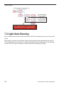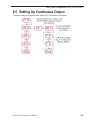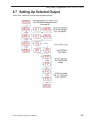
1
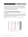
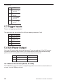
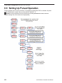
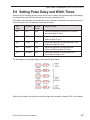
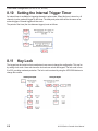
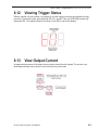
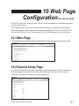
NL-200, NL-220, NL-220F LED Lighting Controller User Manual P/N 84-100022 Rev A 1 Disclaimer Except as prohibited by law: • All hardware, software and documentation is provided on an “as is” basis. • It is essential that the user ensures that the operation of the product is suitable for their application. • The user must ensure that incorrect functioning of this equipment cannot cause any dangerous situation or significant financial loss to occur. • Gardasoft Vision Ltd and Gardasoft Products Ltd will not accept any liability for consequential loss of any kind. All trademarks acknowledged. Hardware, software and documentation are Copyright 2002 - 2009 Gardasoft Products Ltd. Hardware manufactured by Gardasoft Vision Ltd under licence. Latest Manual Version For the latest version of this manual, see the Download Center on our web site at: www.microscan.com. Technical Support For technical support, email: [email protected]. Microscan Systems, Inc. Renton Headquarters Tel: 425.226.5700 / 800.251.7711 Fax: 425.226.8250 Nashua Office Tel: 603.598.8400 Fax: 603.577.5818 Microscan Europe Tel: 011 31 172 423360 Fax: 011 31 172 423366 Microscan Asia Pacific Tel: 65 6846 1214 Fax: 65 6846 4641 1-1 2 Getting Started The NL-200 current controller provides repeatable intensity control of LED lighting for machine vision applications. It includes the intensity control, timing and triggering functions required for machine vi sion systems. LED lighting needs a constant current supply as small variations in voltage can cause large variations in light output. The NL-200 can set currents in steps of 0.1% (with a lower limit of 2.5mA steps) to give very fine control of intensity. Before you start consult your NERLITE specification or product labeling for it’s Current Rating. All specifications can be found on the Microscan website. NOTE: This current rating is critical to the safe operation of the NERLITE, care must be taken to determine the correct rating for the light to be connected to the NL-2XX controller. NOTE: Lighting must not be connected to anything else and must not have a common con- nection to other lights NOTE: The NL series has SafePowerTM low heat technology so that in most cases heatsinking is not required. SafePower also automatically “steps-up” the output volt age, so that from a 24V supply a higher voltage (eg 36V) can be output. 1.) Read the sections on Safety (Section 3) and Specifications (Appendix A) and check the NL-2XX fulfils your requirements. 2.) Mount the NL-2XX as described in Section 4. 3.) Connect the NL-2XX up to a supply as described in Connections (Section 5). When the front panel is present, the NL-2XX should show two alternating lines on the display to indicate that it is operating properly. 4.) Read Lighting Setup (Section 7) and then enter the current rating for the lights you need to connect. Then connect the lights. NOTE: The current release of the NL-2XX does not sup port Voltage Rating, use only Current Rating to operate your light(s). 5.) Set up the NL-2XX for the desired operation as described in the Configuration sections (Section 8, 10 or 11). 2-1 Getting Started 2.1 Summary of Features Throughout this manual, references to the NL-2XX refer to all variants in the NL range unless otherwise stated. The convention for the part number is: NL-cd0-vv NL-cd0F-vv where: NL product range name c Number of channels: 2, 8. d Configuration option: 0 = front panel, 2 = Ethernet F Option for fast pulsing vv Maximum current rating in amps: 2, 20 The following table lists the features on each model. Feature Number of channels NL200 NL220 NL220F 2 2 2 Front panel configuration Yes Yes Yes Ethernet configuration No Yes Yes Fast pulsing No No Yes 2-2 NL-200 Series Controller User Manual 3 Safety Read this before using the NL-2XX. Always observe the following safety precautions. If in doubt, contact your distributor or Microscan Systems. The following symbols mean: Warning: read instructions to understand possible hazard Warning: Possible hazardous voltage Warning. Surface may get hot Where these symbols appear in the manual, refer to the text for precautions to be taken. 3.1 Heat The NL-2XX can dissipate up to 10W and so can get hot. It should be positioned where personnel cannot accidentally touch it and away from flammable materials. Read the Mounting (Section 4). Do not exceed the power ratings given in the manual. Note that at the maximum ratings the case temperature can reach 65°C. Ensure that any ventilation holes are not blocked. Allow free flow of air around the unit. 3.2 Electrical The lighting connections can exceed 46.7V but should not exceed 70V. Pulse peak voltages above 46.7V are considered hazardous. The lighting connections must be shielded from being touched along the whole length of the cable and in the light. The user must ensure that the potential difference between any combination of input signals does not exceed 46.7V. WARNING: Higher voltages may cause a danger to personal health. The NL-2XX does not have complete tracking isolation of inputs and outputs. Transients caused by inductive loads must be suppressed external to the NL2XX. The NL-2XX outputs high energy pulses. Care must be taken to connect the outputs correctly and protect the output wiring and load from inadvertent short-circuits. When switched off, there is still energy stored in the NL-2XX for about 15 seconds. 3.3 General The NL-2XX must not be used in an application where its failure could cause a danger to personal health or damage to other equipment. If the equipment is used in a manner not specified by the manufacturer, the protection provided by the equipment may be impaired. 3-1 4 Mounting In order to provide fixing points to mount the unit onto a flat surface or bracket M3 nuts must be inserted into one or more of the slots in the base, see illustration below. The quantity and position of these nuts is dependant upon the users requirements. To fit a nut remove one of the end covers. The nuts can then be slid into the slots and the cover replaced. Ensure that the fixing screws used do not extend past the lower base surface by more than 5.5mm. See Addendum for installation of optional DIN Rail Mounting Kit. 4.1 Environmental considerations The NL-2XX enclosure is a fire enclosure as long as it is mounted so that none of the connectors are facing downwards. If a fire enclosure is used, the enclosure should be metal or plastic (with a flammability rating of UL94 V1 or better); with no holes below or to the sides of the NL-2XX when mounted. Cable entries below the NL-2XX should be via glands that have a flammability rating as before. The NL-2XX should be at least 10mm from any other part or side of the enclosure. The NL-2XX does not have an IP rating and should be mounted so that moisture and dirt cannot enter the unit. 4-1 5 Connections See the Specification (Appendix A) for information on connection ratings. 5.1 Power Supply To avoid a fire hazard from the NL-2XX or the power supply consider the implications of overheating in the unlikely event of a fault in the NL200. The power dissipation in the NL-2XX in a fault condition can be up to: <Power supply voltage> * <max current delivered by power supply> Either limit the power supply output current so that not more than 30W can be dissipated in the NL200, or mount the unit in a fire enclosure. Choose a PSU that limits its output current by design, by setting the current limit on the supply (if this feature exists) or use fuses. Remember to derate the fuse, if mounted in an enclosure, as the temperature will be higher than ambient. The external power supply will need to be able to supply at least the average output power for all active channels. The use of a regulated power supply with 100% short circuit protection is recommended. If however a non-regulated power supply is used, then the maximum ripple voltage of this power supply must not exceed 10% of the actual DC value. Route low voltage and mains wiring separately. If they must be loomed together ensure that low voltage insulation rating is sufficient or that supplementary insulation is used. Pin Power Input Connector 1 +24V to +48V 2 GND 5.2 Lighting Output The lighting connections can exceed 46.7V but should not exceed 70V DC. Pulse peak voltages above 46.7V are considered hazardous. The lighting connections must be shielded from being touched along the whole length of the cable and in the light. Make sure you set the current rating for a light before connecting it. See the Lighting Setup (Section 7) for details on this. Light output is on 4-way pluggable screw terminal sockets. It is possible to use two 2-way connectors in a 4-way socket. The lighting output connections must not be commoned or grounded in any way. 5-1 Connections Pin LED12 1 CH1 lighting out +ve 2 CH1 lighting out -ve 3 CH2 lighting out +ve 4 CH2 lighting out -ve 5.3 Trigger Inputs There is one trigger input per channel. The trigger inputs are opto-isolated 3V to 24V input, drawing a minimum of 3mA. Pin ET12 connector 1 TRIG1 -ve 2 TRIG1 +ve 3 TRIG2 -ve 4 TRIG2 +ve 5.4 12V Power Output One or two 12V power supply outputs may be present. These can supply up to 1A at 12V for powering external cameras and other devices. Do not connect inductive loads or devices that take large peak currents. Do not exceed the current rating as these outputs are not fused. Pin PW1 connector PW2 connector 1 GND GND 2 +12V +12V 5.4.1 Ethernet Connection (NL220, NL-220F) The RJ45 Ethernet connector requires a straight through cable to connect into a network switch, hub or router. It runs at 10Mbits per second. 5-2 NL-200 Series Controller User Manual Connections 5.4.2 Connectors The NL-2XX is supplied with mating connectors for the power supply input, trigger inputs, 12V power output and lighting output. Should spare parts be required these can be obtained as follows: Connector Description Wuerth part number www.we-online.com Farnell part number www.farnell.com Power Input Wuerth 351 series 2W screw terminal free skt 691-351500-002 164-1952 Trigger Input Wuerth 361 series 4W screw terminal free socket 691-361- 100-004 1642-001 12V Output Wuerth 348 series 2W screw terminal free plug 691-348- 500-002 N/A Lighting Output Wuerth 348 series 4W screw terminal free plug 691-348- 500-004 N/A 5-3 6 General Description The NL-2XX current controller provides repeatable intensity control of LED lighting for machine vision applications. It includes the intensity control, timing and triggering functions required for machine vision systems. LED lighting needs a constant current supply as small variations in voltage can cause large variations in light output. The NL-2XX can set currents in steps of 0.1% (with a lower limit of 2.5mA steps) to give very fine control of intensity. Four modes of operation are provided separately for each channel: • Continuous (“SCo”): In continuous mode the output is a continuous brightness. • Pulse (Strobe) (SPu”): In pulse mode output is pulsed once per trigger. One trigger input is used as a trigger. The delay from trigger to pulse, the pulse duration and the brightness can be set. • Switched (“SOn”): In switched mode a trigger input can be used to switch the output current on and off. The output is only enabled when the trigger input has a voltage on it. • Selected (“SSe”): In selected mode a trigger input can be used to select between two different intensities.. The NL-2XX is set up using the push buttons and display on the front of the unit. The set up is nonvolatile, so the NL-2XX will resume the same operation after a power cycle. 6.1 Output Modes The trigger inputs are used as follows: Mode Trigger Input Output Continuous Unused Output is on. Switched Trigger = off Trigger = on Output is off Output is on Selected Trigger = off Trigger = on Output is continuous brightness 2 Output is continuous brightness 1 Pulsed Trigger rising edge Trigger falling edge Pulse is triggered if P flag = 1 Pulse is triggered if P flag = 0 Note that the P flag inverts the sense of the trigger input. 6-1 General Description 6.1.1 Continuous Output, Switched Output, Selected Output In continuous mode the output current Is fixed and continuous. Switched mode uses a trigger input to switch the output on or off. Selected mode uses a trigger input to select between two different brightnesses. The output current can be varied from 0% to 100% of full brightness. 6.1.2 Pulsed Output The output is off by default. When the NL-2XX is triggered it will wait for a delay and then pulse the output. The delay, pulse width, retrigger delay and pulse intensity are all configurable. Retrigger delay is the minimum allowed time from one trigger to the next. Any triggers that happen too soon after the previous trigger are ignored. The retrigger delay is set in multiples of 100us. In pulsed mode, the brightness can be set up to 1000% of its rating, but only for short periods and at low duty cycles, so that the lighting does not overheat and get damaged. The duty cycle is limited by ignoring triggers which are too soon after the previous trigger. Output Brightness Allowed Pulse Width Allowed Duty Cycle 0 to 100% 999ms 100% 101% to 200% 30ms 30% 201% to 300% 10ms 20% 301% to 500% 2ms 10% 501% to 1000% 1ms 5% So for example, if the brightness is set to 250%, then the NL-2XX will not allow pulses greater than 10ms long. With 10ms pulses, if a trigger occurs within 50ms of a previous trigger (so that the duty cycle would be greater than 20%) the trigger is ignored. If necessary the NL-2XX will limit the duty cycle by increasing the retrigger delay. WARNING: To prevent possible overcurrent condition when operating NERLITE Strobe models, initiate the brightness setting to 10%, then increase current appropriately. 6.1.3 Fault Detection The NL-2XX detects the following errors. When the output current is less than 100mA, some fault detection is turned off. Error Reason PO Internal power dissipation is too high. Output turned off. OP Output current to lighting is too low. The light is open circuit or there is not enough supply voltage for the requested output current. SH If the output voltage is too low, the controller detects that the output is short circuited. HI The voltage required for the lighting has increased too much. Check for ageing of the lighting or a failed LED. LO The voltage required for the lighting has decreased too much. Check for ageing of the lighting or a failed LED. The user must press SEL to cancel the error and the NL-2XX will then re-sense the light. 6-2 NL-200 Series Controller User Manual General Description 6.2 Cold Start The NL-2XX configuration can be cleared to the default settings, which clears the lighting ratings and sets all channels to 50% brightness continuous operation. This can be done from the front panel or by sending the CL command using Ethernet. To clear the configuration from the front panel, turn on the NL-2XX while holding the SEL and DOWN buttons, for about 5 seconds, until ‘COL’ is displayed.. The controller can be cold booted even when the keypad is locked. The lock is removed by the cold boot. 6-3 7 Lighting Setup Lighting can be labelled with either a voltage or current rating or both. All NERLITES will have a current rating, consult specifications or product label. This will be used to setup the rating for the light. This rating is the supply to the lighting that should be used to get 100% continuous brightness from the light. WARNING! When connecting a strobe light to an NL-2XX Series Lighting Controller, you must set the current rating to 10% of the current specified for the light in its configuration guide. The NL-2XX Series Controller allows the operator to set the brightness (current) to 1000% in strobe mode. By setting the initial current rating to 10% of the light’s specified current, a brightness setting of 1000% results in the light receiving 100% of its rated current. This will provide maximum light output without damaging the light. Note: Certain lights require both channels of the NL-2XX Series Lighting Controller. Channel 1 and Channel 2 may have different current specifications on some models. Be sure each channel is set correctly as specified in the light’s configuration guide. The NL-2XX is compatible with both current and voltage rated lighting. Before connecting a light the rating of the light must be entered. If a light is replaced with a different type of light, then the rating must be set first. If a light is replaced with the same type of light then the previous rating will still apply. Consult the specification or labelling for the light. The current rating can be set from 0.01A to 4A in steps of 0.01A. Voltage and current rated lights are both driven with a constant current. This gives better brightness stability and allows the NL-2XX to prevent the light being driven with too much power. 7.1 Setting the Rating for a Light To set the rating of a light on the Ethernet versions of the NL2XX, use the VL command or the internal webpages. To set the rating of a light from the front panel, press and hold the SEL button for 1 second. The display will show “CH1”. Press DOWN to show “rAt” then press SEL. Use UP and DOWN to select the channel to be set up. Then press SEL and select “Cur” to enter the rated current for each channel. Then press SEL and set the current. Press SEL to save the rating. 7-1 Lighting Setup Note: Voltage Rating is not a suported feature. Only use Current “Cur” to enter the rating. 7.2 Light Auto-Sensing When a channel does not have a light connected, the NL-2XX continually tries to put out a very small current. When a light is connected, it will flash for a short time (the light will not be damaged by this) until the NL-2XX detects that it is connected. For voltage rated lights the light is briefly driven at an increasing current until 100% output is achieved in order to sense the current rating of the light. 7-2 NL-200 Series Controller User Manual 8 Front Panel Configuration (NL-200, NL-220, NL-220F) 8.1 Startup For controllers with a front panel, On power up, the NL2XX will display “b r” for 5 seconds, then ‘8.8.8.’ to test the display is working, then ‘NL2’, then ‘00’, followed by the firmware version number, eg ‘001’, and then will be ready for operation. To show that the unit is operating normally, an alternating pattern is drawn on the display. Once a light is connected, the controller will sense it, as described below in Lighting Setup. Note, if light(s) are connected and have no rating specified for them, then an error is indicated. To set the rating refer to section 7.1. The overall structure of configuration is given to the right. To configure the controller from the keypad, press and hold SEL for 1 second. ‘CH1’ will be displayed. Use UP and DOWN to select which feature to set up. Pressing and holding MODE at any time will cancel the operation. Using the keypad it is possible to set the configuration for each channel, set a keylock code so that unauthorised users cannot change any settings, set the internal trigger timer, view trigger status and set the voltage or current rating of each of the channels. 8.2 Setting the Lighting Rating This is described in Lighting Setup (Section 7). 8-1 Front Panel Configuration (NL-200, NL-220, NL-220F) 8.3 Default Display When the NL-2XX is not being configured the display shows the status of all the channels. The segments and their meanings are given below. Errors are usually caused by a light being connected but the rating for that light has not been set. The rating of a light can be set as described in Section 7.1. 8.4 Setting Flags The polarity of the trigger signal (P flag) can be set for some output modes and error checking (E flag) can be disabled. During configuration the user will be allowed to select between the following: • F E Error checking enabled • F - E Error checking disabled • F P Trigger is active high • F - P Trigger is active low 8-2 NL-200 Series Controller User Manual Front Panel Configuration (NL-200, NL-220, NL-220F) 8.5 Setting Up Continuous Output Continuous output is set up as follows. Select “SCo” for continuous operation. 8-3 Front Panel Configuration (NL-200, NL-220, NL-220F) 8.6 Setting Up Switched Output Switched output is set up as follows. Select “SOn” for switched operation. 8-4 NL-200 Series Controller User Manual Front Panel Configuration (NL-200, NL-220, NL-220F) 8.7 Setting Up Selected Output Select “SSe” mode then enter the two brightness settings. 8-5 Front Panel Configuration (NL-200, NL-220, NL-220F) 8.8 Setting Up Pulsed Operation Pulsed operation can be set up as follows. If a brightness greater than 100% is selected, the pulse width will be limited to a safe value as in the table in Section 6.1.2. WARNING: To prevent possible overcurrent condition when operating NERLITE Strobe models, initiate the brightness setting to 10% , then increase current appropriately. 8-6 NL-200 Series Controller User Manual Front Panel Configuration (NL-200, NL-220, NL-220F) 8.9 Setting Pulse Delay and Width Times When the NL-2XX displays numeric values for the user to change, the right hand digit will be flashing to indicate that the Up and Down buttons can be used to change the value. To be able to set pulse delay and pulse width values a scheme is used where the exponent (power of ten) of the value is set. The exponent values are as follows: Exp value Multiplier Number format Range of values E-2 0.01 9.99 Values are displayed in seconds from 10ms to 5 seconds in steps of 10ms. E-3 0.001 999. Values are displayed in milliseconds from 1ms to 999ms in steps of 1ms. E-4 0.0001 99.9 Values are displayed in milliseconds from 0.1ms to 99.9ms in steps of 0.1ms. E-5 0.00001 9.99 Values are displayed in milliseconds from 0.01ms to 9.99ms in steps of 0.01ms E-6 0.000001 999. Values are displayed in microseconds from 1us to 999us in steps of 1us The flow diagram for entering timings on the keypad is given below. When a light is pulsed, the display shows that a trigger has occurred by showing ‘PUL’ on the display. 8-7 Front Panel Configuration (NL-200, NL-220, NL-220F) 8.10 Setting the Internal Trigger Timer An internal timer is available for triggering channels in pulse mode. When this timer is turned on, all channels in pulse mode will trigger on this timer. The delay and pulse width will be the same as for external triggers. External triggers will also work. The period of the timer (the time between triggers) is set as follows. 8.11 Key Lock The keypad can be locked so that unauthorised users cannot change the configuration. This can be by setting a lock code. Users who know the lock code can unlock the keypad. The lock code is from 0 to 255, providing moderate protection. The lock code is entered by using the UP/DOWN buttons to change this number. 8-8 NL-200 Series Controller User Manual Front Panel Configuration (NL-200, NL-220, NL-220F) 8.12 Viewing Trigger Status When a channel is in pulse mode, it is possible to view the trigger input status and whether the light is pulsing. To enter this mode, press and hold SEL for 1 second. Then use UP/DOWN to select “trg” then press SEL. The display below will be shown. Press SEL to cancel this display. 8.13 View Output Current An approximate measure of the output current can be viewed from the keypad. The current is updated approximately every second, but can be slower for pulse mode. 8-9 9 Ethernet Communication (NL-220, NL-220F) You may need to ask your network administrator for advice about setting up the Ethernet connection. Ethernet set up is not affected by cold booting the NL220. 9.1 Connection The Ethernet link uses a 10 base-T connection on an RJ45 connector. The NL-220 Series controller can be connected to a network switch (or hub or router). It is also possible to connect it direct into the network port on a PC by using a crossover cable. 9.2 IP Address The NL-220 Series controller needs an IP address to communicate over Ethernet. There are two ways to get an IP address; either programmed into the unit or using DHCP. Most networks use a DHCP server. If there is a PC on the network, You may be able to find out whether a PC on the same network uses DCHP as follows: • Go to Control Panel • Select Network Connections • Right click on Local Area Connection. Select Properties • From the list, select Internet Protocol (TCP/IP), press Properties If “Obtain an IP address automatically” is set, then DHCP is probably used. However, there may be an alternative fixed IP address on the “Alternative Configuration” tab. You can find out what IP address is being used by a PC at any time by: • Go to Control Panel • Select Network Connections • Right click on Local Area Connection. Select Status • Select the Support tab. The IP address is displayed When using a fixed IP address, you must ensure that you use an IP address that is not being used by any other device on the network. It is usual to keep the first three numbers of the IP address the same as other devices and to change only the last number. For example, if you have a network consisting of a PC (IP address 192.168.1.35) and two NL200s, you might give them addresses 192.168.1.201 and 192.168.1.202. 9-1 Ethernet Communication (NL-220, NL-220F) 9.2.1 Programmed IP Address and DHCP For DHCP mode, the NL-220 Series acquires its IP address, subnet mask and gateway address from a DHCP server. Otherwise the NL-220 Series has a fixed IP address, subnet mask and gateway address. DHCP mode or the IP address can be set and read via the NL-2XX Series Controller Configuration Program available for download at www.Microscan.com. 9.2.2 Automatic Sensing All the features below are implemented in the NL Series Lighting Controller Configuration Program from www.microscan.com. The NL-220 Series will send out a message on three events: • On power up • When an IP address is received or renewed by DHCP • When an enquiry message is received On the first two events, the message is broadcast. On the third it is a reply to a single IP address. An enquiry message is a UDP packet from source port 30310, destination port 30311 with the message body “Microscan Search” (8-bit ASCII, 13 characters). The message output by the NL-220 Series is a UDP packet from source port 30311, destination port 30310. It is formatted as: Microscan, NL220,000000,111111111111,22222222 (8-bit ASCII, 44 characters), where 000000 the serial number of the unit 111111111111 the MAC address in 6 HEX bytes 22222222 the IP address in 4 HEX bytes For example for NL-220 Series serial number 12345, IP address 192.168.1.103, MAC address 00.0B.75.01.80.99 the packet will contain Microscan, NL220,012345,000B75018099,C0A80167 9-2 NL-200 Series Controller User Manual 10 Web Page Configuration (NL-220, NL-220F) The NL-220 Series has a webserver inside, so that it can be configured from a standard web browser, such as Internet Explorer. The IP address of the NL-220 Series must be known (see section 9 on Ethernet Communication. Open a web browser window and type the IP address (for example 192.168.1.71) of the NL-220 Series into the URL box at the top. The main page of the NL-220 Series webserver should be shown. 10.1Main Page The main page shows general information about the NL220. Links are provided to the configuration pages. 10.2General Setup Page The General Configuration page allows the webpage protection password to be set or cleared and the internal trigger to be set up. Also any Ethernet command from Section 11 can be entered. “Test Mode” referred to on this page is the internal trigger timer. 10-1 Webpage Configuration (NL-220, NL-220F) 10.3Channel Configuration Pages There is one Channel Configuration Page for each output channel. All the parameters for each output channel can be set up. Press the Submit button to update the NL-220 Series and save the changes to non-volatile memory. The current rating for the light can be changed. Use this with care. Some measured voltages and the actual output current are displayed on this page. 10-2 NL-200 Series Controller User Manual 11 Command Configuration (NL-220, NL-220F) The NL-2XX can be configured via the Ethernet connection using UDP or TCP/IP. A Configuration Program with source code can be downloaded from www.gardasoft.com. 11.1Ethernet Communication (NL-220, NL-220F) For TCP, commands from a host should be sent to destination port 30313. Replies will be to destination port 30312. For UDP, commands from a host should be sent from source port 30312 to destination port 30313. Replies will be sent from source port 30313 to destination port 30312. A TCP/IP connection will timeout and close if it is idle for more than 10 seconds. The host must send regular “heartbeat” commands (eg “VR”) to keep the link open. 11.2Command Structure Communication consists of commands sent by the host (controlling PC). All output generated by the command is returned in reply UDP or TCP/IP packets. The last character sent is “>” (“greater than” symbol). Once this is received, the host knows that the command has been completed. It is recommended that the host waits for the “>” symbol before sending the next command. UDP communications are not guaranteed to arrive, so the host software must be able to cope with lost messages. Using the GT command, a host can request that a message is sent to it whenever an error occurs. Several commands can be put into one command line by separating them by a semi-colon (“;”). A carriage return character should be sent to terminate the command line. The NL-220 will send any replies to the commands and then send a ‘>’ character to indicate that the command line has been completed. Commands comprise a code of two letters followed by the parameters (if any) needed for the command. Spaces in the commands are ignored. Numeric parameters are separated by a comma (“,”). For a parameter which is a time period the default units are milliseconds. “s”, “ms” or “us” can be added to the end of the number to indicate seconds, milliseconds or microseconds. For currents, “a” or “ma” can be added to indicate “amps” or milliamps”. The default is amps. Note that parameters are in “USA/UK” format so that a half is written “0.5” not “0,5” 11-1 Command Configuration (NL-220, NL-220F) For example: Parameter Meaning 0.1 0.1 milliseconds 200us 200 microseconds 0.1s 0.1 seconds 100ma 100mA 2.45A 2.45A 2.3 2300mA or 2.3A The command codes and their meaning are described below. The upper case commands are shown, followed by lower case letters denoting the numeric argument. Error number Reason Err 1 A parameter value is invalid Err 2 Command not recognised Err 3 Numeric value is wrong format Err 4 Wrong number of parameters Err 5 (This is only a warning) A timing parameter was out of range and has been adjusted to a valid value. Any changes made using Ethernet commands are not saved permanently until the AW command has been issued. 11.2.1General Commands Report the version of firmware running in the NL220F VR This command returns the firmware version. For example: NL-220F Series (HW001) V002 Set the rating of a light This command sets the current or voltage rating for a light. If a current rating is being set, then the voltage rating value should be 0. VLo,v,c Where: o = output channel (1 or 2) v = voltage rating (NOT SUPPORTED Set to 0) c = current rating (0 or 10mA to 4A) 11-2 NL-200 Series Controller User Manual Command Configuration (NL-220, NL-220F) Set continuous mode The output is set to continuous mode at a percentage of full brightness. RSc,s Where: c = output channel (1 or 2) s = setting in percent (s = 0 to 100) Set switched mode The output is set to switched mode at a percentage of full brightness. RWc,s Where: c = output channel (1 or 2) s = setting in percent (s = 0 to 100) Set selected mode The output is set to selected mode with two brightness settings. RUc,s,t Where: c = output channel (1 or 2) s = brightness 1 setting in percent (s = 0 to 100) t = brightness 2 setting in percent (t = 0 to s) Set pulse mode The output can be set up to pulse on a trigger input. The delay from trigger to the start of the pulse, the length of the pulse and the brightness are configurable. An error is generated if the brightness setting requires a current greater than 20A or if the combination of pulse width and setting is not allowed. RTc,p,d,s RTc,p,d,s,r Where: c = output channel (1 or 2) p = pulse width in milliseconds (0.02 to 999) d = delay from trigger to pulse in milliseconds (0.02 to 999) s = setting in percent (s = 0 to 999) r = retrigger delay. This parameter is optional Set the Option Flags REc,m Where: c = output channel (1 or 2) m = flags: 0 E flag set (error detection enabled) bit 1 = 1 E flag cleared (error detection disabled) 0 P flag set (positive triggers) bit 2 = 1 P flag cleared (negative triggers) 11-3 Command Configuration (NL-220, NL-220F) Set the Trigger Input This command sets which input is used for pulse and switch output modes. RPc,p Where: c = output channel (1 or 2) p = trigger input (1 or 2) Set Internal Trigger Enable or disable the internal trigger. When enabled, all outputs are triggered simultaneously using an internal trigger signal. This setting can be saved to non-volatile memory using the AW command. Disable internal trigger TT0 Enable internal trigger (uses previously set period) TT1 TT1,p Enable internal trigger and set the period Where: p= period of the triggers in microseconds For example: Set the internal trigger to 200ms (5Hz) TT1,200 TT1,500US Set the internal trigger to 500us (2KHz) Save the settings to memory. AW Once the settings are saved to memory they are then retained when the unit is switched off. If this is not done, changes to the settings are volatile, and if the unit is switched off they revert to those in force when the last AW command was issued. Simulate an Input Trigger TRc which input channel (1 or 2) c Simulates a trigger pulse. If the channel is in pulse mode it will pulse and show “PUL” on the display. Enable Ethernet Messages GTm = 0 to disable Ethernet messages m = 1 to enable Ethernet messages When Ethernet messages are enabled, any error reports are sent to the most recent UDP or TCP address from which a command has been received. Messages are of the form: Evtc,e zero for no channel or channel number (1 or 2) Where c v event value: 32 to 47 Lighting er or code 128 Light detected and waiting for current rating 129 Light detected and not waiting for current rating 11-4 NL-200 Series Controller User Manual Command Configuration (NL-220, NL-220F) Clear any Errors GR If Ethernet messages are not enabled, the last event or error number can be read by this command. Any error displayed on the unit is cleared, so if there was a lighting error, the NL2XX will resume auto-sensing on that channel. The reply will be in he same form as the GT command above. If there are no outstanding events or errors, then only the prompt “>” is returned. Set/Clear the Webpage Password EY EY asc1, asc2, asc3, asc4, asc5, asc6 This command sets the password required to access the webpages. If EY is entered on its own then the password is cleared. There are six optional parameters, which are decimal ASCII values for a password from one to six letters. A value of 65 is ‘A’, 66 is ‘B’, etc to 90 is ‘Z’. Disable Keypad KBd,c Enable keypad d = 0 Disable keypad, but allow unlock code d = 1 Disable keypad, disable unlock code d = 2 Unlock code c In some applications it may be necessary to lock the keypad so that un-authorised operators cannot change the settings. A unlock code can be set. This can be used as a low-security way of allowing trusted users to unlock the keypad. Ethernet commands and the web pages still work. The setting of this command is restored after a power cycle. 11-5 Command Configuration (NL-220, NL-220F) 11.2.2 Command Summary Command Example Effect AW AW Save changes GT GT1 Enable Ethernet messages GR GR Clear any error condition. EY EY65,66 Set webpage password to “AB” VR VR Read the firmware version VL VL1,0,0.5 Set the rating of channel 1 to 0.5A RS RS2,65 Set channel 2 to 65% brightness continuous RW RW1,50 Set channel 1 to 50%, switch mode RU RU1,75,25 Set channel 1 to selected mode at 75% and 25% RT RT2,3,4,50 Set channel 2 to 3ms pulses, delayed by 4ms, at 50% brightness RP RP1,2 Output channel 1 is triggered using input 2 RE RE1,3 Set channel 1 to ignore lighting errors and not prompt for the current rating of a light when it is connected TT TT1,1ms Set internal triggers every 1ms KB KB1,23 Disable the buttons on the front panel. Set the unlock code to 23. TR TR2 Trigger channel 2 NOTE: If the above commands are executed using the Web Page feature, they will not be executed in the command entry area of the Web Page. 11-6 NL-200 Series Controller User Manual A: Specifications Output channels Up to 4A continuous or 20A pulsed. Maximum 48V output, 60W average total output power Lighting Rating 12V to 36V in steps of 1V 100mA to 4A in steps of 10mA Operating modes Continuous, strobe, switch and selected Trigger inputs opto-isolated, standard or inverted operation. 3V to 24V Pulse width (NL-200, NL-220) 20 microsecond to 1 second. Repeatable to 0.1 microsecond Pulse width (NL-220F) 2 microsecond to 1 second. Repeatable to 0.1 microsecond (See Restrictions, Appendix B) Trigger delay (NL-200, NL-220) 20 microseconds to 1 second. Repeatable to 2 microseconds Trigger delay (NL-220F) 2 microseconds to 1 second. Repeatable to 2 microseconds Internal trigger timer 0.2Hz to 5KHz Supply voltage 24VDC to 48VDC regulated Heat Dissipation 2W per channel typical at maximum output A-1 B: Restrictions The following timings and restrictions apply for firmware revision V002. The restrictions are applied when settings are saved. Later firmware versions may have lesser limits. B.1 Continuous Mode The maximum output current is 4A. B.2 Switched Mode The maximum delay from a trigger input changing to the output current being turned on or off is 10us. The maximum output current is 0.5A. B.3 Selected Mode The maximum delay from a trigger input changing to the output current being turned on or off is 5ms. The maximum output current is 0.5A. B.4 Pulse Mode The maximum output current is 20A. For high currents pulses the following limits are recommended. These limits will be improved in future. Pulse Current 20A 12A 10A 5A Pulse Length Limit 100us 400us 500us 1ms Pulses of 2A or more for pulse widths longer than 2ms might cause an error or have a lower current towards the end of the pulse. The minimum pulse delay is about 2us. When overdriving or using the retrigger delay, the minimum delay is around 5us. For pulse widths less than approximately 70us the output voltage and current cannot be measured. Because of this, fault detection does not happen and the following restrictions apply: • • For pulse currents greater than 0.5A, the duty cycle will be restricted to no more than 1% For pulse currents less than or equal to 0.5A, the duty cycle will be restricted to no more than 10% B-1 C: Fatal Error Codes Error number Reason FAt, Err 44 The NL-200 is too hot. The NL-200 has a thermal cutout which operates around 65°c to 70°c, depending on conditions. FAC, Err 40, Err 41, Err 45 One channel is outputting more current than expected. C-1 D: Error Codes Error number Reason Err 1 A parameter value is invalid Err 2 Command not recognised Err 3 Numeric value is wrong format Err 4 Wrong number of parameters Err 5 This is a warning, not an error. One of the parameters is out of range. The value of the parameter has been adjusted. For example, sending an NL command with a delay of 0 will get a reply of “Err 5”. The command will be accepted and the delay set to the minimum allowed. Err 19 A light has been connected to a channel but the rating has not been set. Err 8, 12 EEPROM corrupt. The configuration has been cleared. Err 9, 20 Couldn’t save settings to EEPROM. Err 27 Can’t read Ethernet settings from EEPROM, so these may be incorrect. PO, Err 34, 39 Internal power dissipation is too high. Output turned off. OP, Err 35 Output current to lighting is too low. OP, Err 43 There is not enough supply voltage for the requested output current. SH, Err 36 The output is short circuit. SH, Err 42 The output current is too high. HI, Err 37 The voltage required for the lighting has increased too much. Check for ageing of the lighting or a failed LED. SH, Err 38 The voltage required for the lighting has decreased too much. Check for ageing of the lighting or a failed LED. Any other errors are internal errors. D-1 E: Event Codes Event messages are sent when a light is connected or an error occurs. The format of these is Evt<channel>,<event code>; These event messages are only sent after the GT1 command has been sent. Event number Reason 1 to 127 An error has occurred. The error code is given by the event number. 128 A light has been connected and is working. 129 A light has been connected but doesn’t have a current or voltage rating. 130 Over temperature error occurred ( FAT) 131 Over current error occurred (FAC) 132 An error has occurred while autosensing the rating of a light. E-1 Addendum Installation – see figure • Remove either end cover by removing the four screws. • The clips shown indicate the two orientations available for mounting. • Select the orientation required, a pair of clips is used for each (AX or AY). • Slide nuts (B) into the appropriate slots. • Replace the end cover. • Screws (C) are passed through mounting clips (A) and into slot nuts (B). • Position the loose assemblies as required and tighten the screws. DIN Rail Mounting Kit for NL Range Pack Contents Description Drawing Ref Quantity Mounting Clip A 2 M3 Nut B 2 M3x8mm Countersunk screw C 2 A