1
Juspoint D
VECTOR CONTROL
INVERTER POSITIONING
SYSTEM
SPECIFICATIONS/FUNCTIONS
a
“;;
CertlflcateNo B 950322945001
YASUAWA
DTSE-S606-9,1
CONTENTS
.............................................................................................................
3
...........................................................................................................
2 SPECIFICATIONS
5
...........................................................................................6
3 SYSTEM CONFIGURATION
1
INTRODUCTION
3.1 INTERCONNECTION
....................................................................................
DIAGRAM
3.2 MAIN CIRCUIT TERMINALS
6
................................................................................ ..
TM1
8
.................................................................
3.3 CONTROL POWER INPUT TERMINALS TM1
8
........................................................................ .
3.4 ENCODER (PG) CONNECTOR (CON2)
8
................................................................................ . .
3.5 l/O SIGNAL CONNECTOR CON1
9
3.6 WIRING PRECAUTIONS
4 DESCRIPTION
"""""
"""""
"""""
"""""
"""""
"""""
"""""
"""""
"""""
"""""
"""""
"""""
"""""
"""""
"""""
"""""
"""""""""""""lo
OF OPERATIONS
"""""
"""""
"""""
"""""
"""""
"""""
"""""
"""""
"""""
"""""
"""""
"""""
"""""
"""""""""""""""do
4.1 FUNDAMENTAL OPERATIONS
"""""""""""""""""""""""""""""""""""""""""""""""""""""""""""""""""""""""""""""""""""do
4,2 SETUP
"""""""""""""""""""""""""""""""""""""""""""""""""""""""""""""""""""""""""""""""""""""""""""""""""""""""""""""""""""""""Al
4.3 ZERO-POINT
4.4 ZERO-POINT
RETURN OPERATION
"""""""""""""""""""""""""""""""""""""""""""""""""""""""""""""""""""""""""""22
SETUP OPERATION
““””.
”””””””””””””””””””.
”””””””23
OFFSET AUTOMATIC
4.5 AUTOMATIC OPERATION
""""""""-"""""-""""".-".. as."".-"."""""""""."."". """."".."" """"""""."""."S."""."""""""""""24
4.6 MANUAL OPERATION
'""""
."".""""""
"""""
"""".
""."""."""""
"""""
"""""
"""".
"""."".""
"""""
"""""
""".""".""."""""
..""""25
4.7 EMERGENCY STOP OPERATION
"""""".""""".""•
."".."•"""""
"""""
".""..""..".""""
"""""
."".""."".."".."".""."."26
4,8 JOG OPERATION
"""-"
""-""
""-""
.-".""."""""
"""""
"""""
".""."""."".."""""
"""""
"""."".""
..""."""""
"""""
"."""
.""""
".""".
"26
5 PARAMETER
SETTING/MONITORING
5.1 PARAMETER
"""""-".. ".-". s-.."-"""""""""""-"".""." ".."" """""-.""-"""""."""."""""""""""-"""-""""""""""""""27
STATUS MONITOR
"""""
"""""
"""""
"""""
"""""
"""""
"""""
"""""""""""""""""""""""""""""""""""""""""""""35
5.2 OPERATION
5.3 HOW TO USE PARAMETER
5.3.1
5.3.2
5.3.3
5.3.4
5.3.5
"""""
"."""
"""""
"""""
"""".
""""""""""""""""""""""""""""27
SETTING
SETTER (Model JVOP-1OO)
““-””
”””””
.”””.s”.””
”””””
”””””38
““”””
”.”””
”””””
”””38
Parameter value setting flow (Co-nn, do-nn, Eo-nn)
"""""
"""""""""""""""""""""""""""""""""""""""""""""39
Monitor operation flow (Uo-nn)
"""""
"""""
"""""
"""""
"""""
"""""
"""""
"""""""""""""""""""""""""""""""""""""""""""""39
Parameter initial value setting flow (So-nn)
"""""
"""""
"""""
"""""
"""""
"""""
"""""
"""""
"""""
"""""
"""""""""""""do
Teaching method
"""""
"""""
"""""
"""""
"""""
"""""
"""""
"""""
"""""
"""""
"""""
"""""
"""""
"""""
"""""
"""""
"""""
""""""""""""""do
Fundamental
operatio flow (mode selection,
5.3.6 Supplementary
6 1/0 INTERFACE
description
OF SEQUENCE
6.4 TIMING OF SEQUENCE
6.5 ABS MODE 1 AND 2
7 STATUS/ALARM
""""""""""""""""""""""""""""""""""""""""""""""""""""""Al
""-""""""""".""".""-"."""""""""""."""""".""".""""""""""".""""""."."""."".. """""""""""""""""42
............................................................................................. . . . 43
INTERFACE
6.3 SUPPLEMENT
setter)
number selection)
"""""
"""""
"""""
"""""
-."."""+""
"+..""""""
"""""
".."""""
."""."".""
"""""
"""""
"."".""..""..""""""""""""""""""42
6.1 INPUT INTERFACE
6.2 OUTPUT
(for parameter
parameter
CONTROL
CONTROL
OUTPUT SIGNAL
SIGNAL
““””””””””””””””””””””””””””””””””””””44
"""""""""""""""""""""""""""""""""""""""""""""""""""""""""""""""44
"""""
"""""
"""""
"""""
"""""
"""""
"""""
"""""
"""""
"""""
"""""
""""""""""""""""""""""""""""""""""""""'"""""45
INDICATION
7.1 STATUS INDICATION
"""""
"""""
"""""
"""""
"""""
"""""
"""""
"""""
"""""""""""""""""""""""""""""""""""""""""""""47
(On the point module)
7.2 TROUBLESHOOTING
""""""""""""""""""""""""""""""""""""""""""""""""""""""""""""""""47
""."""""
.""."".""".".."""""
"-"""
"".""."""""
"""""
"""""
"""""
"""."
"".""
.""""
"""""""48
8 PRECAUTIONSON
APPLICATION"""" .""""
"""""
"""""
"""""
"""""
""""..."..5O
.........................................................................................................................51
9 OPTION
................................................................................................
9.1 PARAMETER
SETTER
9.2
9.3
9.4
9.5
PG CABLE
....................................................................................
SETTER CABLE
51
..................................................................................................................
PARAMETER
SETTING SOFTWARE
PARAMETER
PERSONAL
COMPUTER
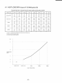
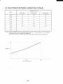
10 CHARACTERISTICS
51
COMMUNICATION
(Speed-Torque
51
““””””””””””””””””52
““””””””””””””.
””””””.
””””””””52
(Personal computer software)
CABLE
Curve)
""""'
"""""
"""""
"""""""""""""""""""""""""""""""""""""""""""""53
in mm (inches)
"""""
"""""
"""""
"""""
"""""
"""""
"""""
"""""
"""""'""""""""""""""""""""""""""""""""""""""53
11,1 CONTROLLER
"""""
"""""
"""""
"""""
"""""
"""""
"""""
"""""
"""""
"""""
"""""
"""""
""""""""""""""""""""""""""""""""""""""""""""""53
.....................................................................................
11,2 DIMENSIONS in mm (inches)
54
–2–
11 DIMENSIONS
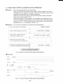
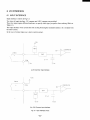
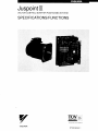
1. INTRODUCTION
Juspoint
station
IIl is the newest
indexing
positioning
member
and positioning
system
designed
of our inverter
control.
drive family,
developed
It is an economical-cost,
to drive actuators
for Numerical
exclusively
for
easy to set, reliable
Control
machine
tools.
The controller includes YASKAWAS vectorThe system consists of a motor and a controller.
control inverter “X3000 series” with “Point module” (Positioning control board). The “X3000
series” features high-torque and precise speed control over a full speed ranged from O to
1800r/min. “Point module” can configure up to 120 different parameters for application
flexibility.
The motor is a highly efficient, three-phase AC induction motor, exclusively designed for high
performance vector-control applications. Juspoint IIl positions accurately and rapidly in the
same way as a servo drive and it is ideal for servo driven tool changer applications for
machine tools.
In addition, compared with the cost of conventional AC servo drives, Juspoint Ill is an
economical alternative for tool resting, magazine attachments, Automatic Tool Changers
(ATC), and Automatic Pallet Changers (APC).
FEATURES
■ Juspoint
IIl can position
up to 511 station
■ Juspoint
Ill can operate
rotary
Rotary axes
●
●
Linear axes
●
●
■ Juspoint
numbers.
and linear axes.
Juspoint D can position up to 511 stations equidistantly.
Juspoint Ill can automatically compensate positioning when the number of
pulse between stations is a fraction.
Juspoint III can position up to 511 station equidisttitly.
Juspoint Ill can arbitrarily position up to 45 stations.
IIl can perform
Absolute
(ABS) positioning.
Using the motor with a special brake, Juspoint III can perform ABS positioning and no zero-point
return operation is required even without a mechanical clamp when the power is ON.
■ Juspoint
III can arrange
■ Juspoint
III has 6 operation
Automatic.
■
parameters
in up to 4 operation
patterns.
modes:
manual. set-up, zero-point return, automatic zero offset, tind JOG.
120 parameters
available
for configuring
Juspoint
-3-
III to your specific
requirements.
Juspolnl ❑
“v-–l
Tr.
—- ;
CONROLLER
.
FQIM
WWK
MOTOR
X 3000
[d +~-~
_l /0
Pc
NC
91GITAL
[lPERATOR
nL
‘‘
FOR POSITION COtJNTtR
i.1
‘
‘
--------
—0
MACHINF
IM
~ ENCOl)ER ‘ F
-
a
~
PLC
NC
CPU
‘1
Three phases
200VAC
POWER
SUPPLY
1.
_
--..-11
I
~
‘4
;-: I
‘-—u
II
I
!n
J
X 3000 series motor
(For vector control)
Fig. 1.1 Juspoint~
System Configuration
DANGER
~
●
Do not touch circuit components until CHARGE lamp on X3000 series PC board extinguishes
after turning off AC main circuit power.
The capacitors are still charged and can be quite dangerous. Wait approximately five minutes
after AC main circuit power is OFF.
●
Do not connect or disconnect
wires and connectors
●
Do not check signals during operation.
while AC power is applied.
IMPORTANT
●
Bc ~ure to ground Juspoint III using mounting bolts.
●
Do not provide c:ip:ic itor or mtignctic contac(or between Juspoint Ill ~md motor.
●
Do no~perform
[he following tests in the field :
Withstand volt[~ge (cst on any p~irt of the Juspoint ~.
and vulnerable to higll-volt~~ge.
II is 2u1electronic
device using semiconductors
lnsui~ition resis[aocc test with :t megger. Thi\ test has been m~~de a( the tttctot-y tind need not be
conciuc[ed :lt test run. Excep[ion:
If megger-testing
is required l’or inspection and main[en:mce
purposes, it should bc :Lpplied only to m;iin circuit and the ground ~md never to the control circuit.
Conduction
test 00 control circuits.
–4–
I
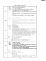
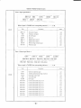
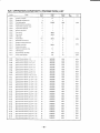
2. SPECIFICATIONS
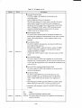
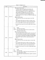
Table 1.1 Specifications
Model CIMROutout kW [HP]
Cur;ent(A)’ ‘
Power Supply
Input Current
~ ~Control Method
s Power Element
2 ~~aklng Method
Speed Control Range
; Speed Resolution
Ambient Temperature
Power Supply
02JP3
04JP3
02(1/4)
04 (3/4)
20
30
.-L–Three phases
180 tO 242V 56Hz
A
1 g___
~
Basic Operation
>1
~
Pos!t[omng Command
axis
axs
axis
axis
~below
~At motor axis)
Total 120 parameters (Dlgltal operator JVOP100 or settlnq by p ersonal
O 2kW
0.4kW
O 75kW
~
1 5kW
0 ?4/4)
. _ 04 (3/4 L_.
075Q)
!3[2)
!
l_08
29.
74
A..
.——
_
1 o~
212
79~
_
— -- 398_,.
..1.
60
_~:’o
15
15kW
?2
? 7kW
’37
3 7kW
, --g
‘-’l
1
mode
Zero point LS
ABS pos[tlon start
Curren[ station
computer
2.2kW
IS also possible ~
----
_=~---
9675
__~070
‘---1
Y-
■
Z, phasgs)
)907~RH or below
I
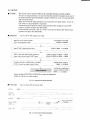
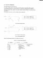
Controller (X3000°series + point nlodule)
Instruct Juspoint Ill by model
shown in the example below.
number differs according
to
interfaces. Specify output, cooling
interface specifications.
numbers us
The model
control
1/0
method. and
C I M R – ,...::...:
:--””’’”--””’
J P 3 –[:::;[::: O 0 M
T
Brake Spec
tj N[>O,icklasll
Holdlnq brake
T (DC24)
Shaft options
s ,,’11!1
011Sec+l
K ‘tiltl] <Cy
(Slar[iard)
I W!I1 key .ild
+>J
011 seal
Des[gn revision order
D X3000 Jus~O ,,1 III
(20mln )
__
IDAA
,,
Optlgajc_j_OOO puls~~,
-10 to +40”C (+14 to+104F
Humldlty
3.7kW
3~
160
1962
22 (3)---—.
IL
IIQ6
_L
~..
Class B
4070 ED (30mn )
1800r/mln (4 pole~..
T
kW
rated~~~
145_
UAJPEE–08DK2KU
04
1!?.
ProvtdeQ~O to 100m2~&}
‘-:-1
Provided
Provld~slng
motor wth bra~e~__
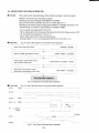
Instruct the motor by model numbers as shown
in the example below. Specify output and
whether with / without brak~.
(With ABS positioning, order the motor with
brake. )
() 75kW
.<.
___ 0 to 720~@-rotatjon
aj_~Qtor axm.
lo to 5000 rmsec_~Oto 1800r/Mln)
9 Motor (exclusive motor for X3000 series)
04
‘-85
.
Set-up
Manual
~utomatlc
zero offset _
_
9 blt binary code (Max 511 slatlons)
9 b(f binary code
Pos[tlor>ng command Drectlon command
Start comrmand
Operatng
Emergent stop
Reset
Numercal pattern Servo on
Poslfon completion
Poslttonlng near width Zero speed
Alarm
4BS ~stlon completion
..pM[lonln*uracy
__
Operation Constant
Model UAJPEEDK2K
outp~
kW (HP)
Raced Curr~nr_
A
Rated To~que
Nm
~ Maxjrn~rn Torque
Nm
g M~nt
lne~of
J (GD2/4J kgcm
~ jn:glatlon
Class
08
L-- _I
&l_800r/m
n
~/~OoOIO
3r/mln)
_
~+55’C
(+~+131”F)
24VDC (~4V)
250mA
Equldstant staton (Sngle station pulse IS an nteger)
Equldlstant station (Sngle s[atlon pulse IS a fracton)
Equldlstant sta[lon
Arbltrarv station distance
Zero-point return (2-mode)
JOG
Au to_rna~c
o‘ CtiTrent Posltlon Output
m:
Input Signal
g
m’ Output signal
?
Backlash Corn]ensatlon
A~cel Time
Soft Star[
Soft S~opplng
,ABS_PosItIon~
1
37JP3
37 (5)
175
PWM vector cotrol
Control AxIs
I
1
15JP3
22JP3
15 (2)
2 ? (3)
75
110
__
Three phases
180 to 253V, 60Hz
L-.-4 8
_< o
Rotary
Rotary
Linear
Lnear
Time Rated
_
Ra!g~>eed
Enclosure
———, E~coder
Ambient Temperature,
08JP3
075(1)
45
X Others
Mounting opt[ons
1 Flange type .apcred
Sbc+fl
Fl~)ge tyDe s[ral(jh[
shaft
—
Detector
K f OOOP/H
2
—5
output
Strwture
Interface InW/Output
02:
04:
08:
15:
22:
37:
1: Heat sink instal~
in t~ pati
3: tit sink imtal~
out of tt!e WA
A : OV OVbmmon
B : 24V 24V Commn
0.2kW
0.4kW
0.75kW
1.5kW
2.2kW
3.7kW
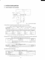
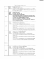
3. SYSTEM CONFIGURATION
3.1 INTERCONNECTION
DIAGRAM
—
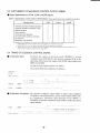
(1) Specifications
of peripheral
equipment
for main circuit terminals
and cables
Table 3.1 Peripheral equipment and cables specifications for main circuit terminals
_02 .1P 3
CIMR=__
Mclgllc[lc C[)llliicl(ll V<ldcl
M;IIII circ{lht tvrrl;lr>itl
c:ihlc< \p~~l[ IC;+lIIIT>
\l[)del
I-
(’ilhlc SILC
15.IP3
08 J}’ 3
04JP3
HI-7E
1 - --–-~-J=Cc!hlc SILC
SLrCu <11:1. M4
2111111
~~Jrj
]__
37JP 3
_Hl-20E-
35,,, !,,:
Screw dIiI.
M4
Table 3.2 RecommendedMolded-caseclrcultbreakers (MCCB)that havebeencertifiedby EuropeansafetystandardEN
02 IIJ3
\lo(icl.(’IklR -
M(’CB
Elcc[t]c
[TI:]dv
Ih>
04.1P 3
0XJP3
I/\ 33
\fC(-13 [II:!<Ich) F~L]L
Electr, c
SA ~3B
(41i\’,\(’.
Nf 30-(’s
MLt\LLhL\h) \F ~,).s5
““EA 33
SA 3313
( 415 VA(’. 10A]
NF 30-CS
NF 30-SS
(415 \’AC. 10/4)
5A)
( 415 VA{’. 5A)
~~J,, ~
L
——–— ]S]p?
E,/\ 33
SA 33B
—.( 415 \’A(., 204)
NF {()-(ShF 30-SS
( 415 \’AC, 20/\)
_
37JP7
‘EAl\
SA 3313
( 415 VA(’. 30A)
NF 7(1-CS
NI 70-SS
( 415 \’,4C. 30A)
(2) Specifications of cable and receptacle for encoder (PG) terminal and CON2 connection specifications
Table 3.3 Cable and receptacle specifications for encoder (PG) terminal
M,)dcl
N;,,nc
Sl, <h,ghl ____
A,>g,)l.+r
c’.,hlc (’1.,,,lp
-.,
PI,,:
,
(’,,
I
,!,
‘<!hlc,1<11],.rl~lh.
11P 1,1
,,.
Rcnli,]-k,
~
I
ifs 3[()(>ll?()-?~)s-zh
\lS 7 I [IX 1120
-2~)S-ZN
MS 31)57-12,\
. . . . . . . ..
‘1.1L’.
~olll.A~(;24 <?,].,,PL’,‘,,
,,,,,1 1,>,Ic,,;lh.
,,,,
;(, l(lo”,.~.,,c c.,,],
1<) he
l\L, \lcci [,>
I ()\J 11[1..
AW(;22 <), I.irycr c<khlc.]
NtItc The MS3 102 A 20-29P recepl~cle r]lade by JAE 1$liied.
Table 3.4 CON2 connection example
N>IIIIe
Socket hc)tl~lng
Ct)nl~;t
(3) CONlzonnection
Rc[llilrL\
\l<iclc h> .1,4E
M.LIIchy JAI:
Model
I
PS-D 4C 10
I 03-5 I 307-()()1
specifications
Table 3.5 CON1 connection example (maker: JAE)
Name
Hou\~
Socket c[)nt:ict
M:IrIual crimpitlg tc)c)l
C’c)nnectc)r
:=
. ____
Stfiiln rellcf
: “ “oG
&3Es
Pre.. \M.lr{I.<, .t~:!r,di..
a
~u
.C m
bc
-—
rm:,;h,..
T) ])c
PS-D4 C.50
.o~~s I 11)4-1)()I
CT 15(1-I:PS:~F
PS-50SM-D4Pl-jCA
PS-SR 50fi– ‘–— ‘-——...—.*
kfiT. PT<E
(1.1 R
-6-
;(l~>ole,
W,(I,
Specll’lc:ltlc]n\
lIIc(>r,ect-III\crt Lc>[I-~r[,(Il
h,>
; #24 i{)#?x
I ~(1.p,llg,h lth
~– . . .
.
111’{lrl.,t.ill\.rl,,,ll-[,,
(,,:!~c~_
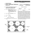
Layout of Juspoint Ill
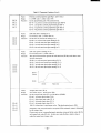
(4) Component
Table 3.6 Lead Specifications
of Control Power Supply Input Terminals
Leiid si~e
Specifications
~ Terminal
screw d]~m]e[er
I
—
2mmA
M4
Dn\AIKR
❑
Ic 1
POINT
MODULE
/
IN VERTER
Juspeed-F X ]()[)()
/
,,”,
)1
R
s
INPuT
T
u
Jc
Vw
L) UTPUT
Fig. 3.2 Component
–7-
Layout of Juspoint ~
Q o MAIN CIRCUIT TERMINALS
TM1
O.c
Table 3.7 Names and outline of main circuit terminals
“*niL:,6”I+,
Main circuil pnwer
I
3.3 CONTROL
u“v “w
I
Motor cnrlnccticm
{ermitla]s
Three-phase
200/220” VAC (f I()% )
L; anti mn[nr’\ (; tcnnlrral. V atlci mnlur’s V tcnnimll,
~ W atlci mulc)r’s W tcrrnin:il
POWER INPUT TERMINALS
TM1
Table 3,8 Names and outline of control power input terminals
s ymbul
1
‘1
Name
Pnwer terminal
—–~Pt>wer lcrmlnal
3.4 ENCODER (PG) CONNECTOR
,
I
! 24VDC power
Outlitlc
! OVDower
(CON2)
Names and outline of encoder (PG) connectors
Table 3.9 Names and outline of encorder (PG) connectors
Outline
Numhcr
Name
Al
P(Jwet- terminal
5VDC
BI
Pc>wcr lermir]al
GN[) (OV)
A2
Pha\c A ]I)put
B?
Pha\e A OV
‘-A3
B3
(CON2)
—
Pha\e B input
Signal lerminal
A4
Phase B OV
—
Phase Z input
B4
Phase Z OV
AS
Thermis[cr Input
B5
Thennister OV
Pin arrangement
—
of CON2
B1
B?
B3
a4
..
B [)
Pin header
B
Housing
-8-
Al
A2
A3
A4
A5
3.5 1/0 SIGNAL CONNECTOR
(1) Terminal arrangement
CON1
of 1/0 signal connector terminals
Table 3.10 Terminal arrangement
Iurnhcrl
I
Synlhol
Descri~[icm
I
+24V pclw,cr Sf)urcc
+?4V
,1 I
of 1/0 signal connecter terminals
(umbe
SymhrrI
BI
+?4V
OV
A3
STA. NO ()
c’omm~lnd inpu~ nt s(:illun nunlber
B3
A4
S’I’A. N() 2
C[)llllll;l!l<i
lllpLlt of sl:lllO1l lllllllb~l
B4
,{5
STA.N()
4
[’[)mnliuld
I]lpllt [)f \litl Ic)n nun]het
B5
‘A(,
ST. AN() (,
C{)]l]llliuld
inpu[ 01 \l:ill[>n number
:{ 1
S’1A N() x
(’(>n)m>in([ ]nput [)1’\[i~[ic)n number
OV po\icl- \oulcc
/4x
F’/l<
Al)
M()[>r: I
A I ()
AI I
SVON
,\12
YILI[.T. ()
Nh/\u
:115
,\[.,\l<h4
(m>m.u)cI ]npul (~t st:ltion nurnher
STA.~mImLUICl
START
B7
[)1 (ll>C~L1t!O1l
Bll
Llltllll>lc-[;iillcr]l Sclcctlcjn inpul
opcr:lllnn
B12
cotnple{ton” \Ign2tl [lulpu[
B13
P[)slllt)nlng vIc Iml! \igni(l (Iulpu(
I’OS. N()
A17
t’OS. NO 3
I
B14
r
1Multlplc-p,i[[ctr
‘M,j,T~-
COIN-A
_ ZSF’D
~zer,,;,>ccds,S,,,;\
B15
B16
POS. N(> ~ 1Lurrcnt ,I:lt](m
CUIICI1l
B17
POS, NO 4
—.
PC)S. N() 6
Curren[ s(~ttl(m number ou[pu[
POS, N() X
(’urrcnt ilatt(m numhcr ;LIlpu[
Stiltloll
number
OLIIPU1
1’OS.N() 5
Currcnl st:it,c~nnun,hcr <)urpul
~Lll~C(ll
Stil( loll
llU1llhC1
BIX
Bl~
[) U[pU[
~
/\20
ARS. RE.AI)Y
Nlcn)(lr! s[or,i~c III lBS ITIt)clc
cunlplc(eduulpul
B20
OPT. ()(IT ()
A’2 [
““
+24V power SOLJt-cc
B?l
+?4V
oi”
A?4
N(
NC
A25
OV
— OV power ic)urcc
_l
\l:l{iot) nUnlbCI- outptll
--–—
-
NC
HOUSING
–9-
nLlnlhcr
uulput
Current sl;l[ion nun]hcr uutpu[
Spilre oulput
+24V power source
OV p(~wcr s(~urcc
O“PT IN ()
Sp:trc Inpil
Nc
“–
Llcnltlr!,Ior:igc(n IBS ITI(ICIC
con]pletcdIiIput
CON I Din
t’l N HFADFH
‘-
Cur-rent \[:([L<)n [nunlhcr output
l> OS.N() 7
f\Bs. S’r
o;,tp,,;
l>OS ~~ () I Currcnl
Alx
A ?.4
sclcctlun inpu[
~ iutcllmiitlcp[]\Il)[lmIIs c(lmplctlt)tl\]~n:il L)(IIPU[
Al:irm \Isn:Il t)utput
,1]c)
+~~y
input of npcrziric)n n]c)dc
Blo
Zct-(l-pc)itlt 1.S si~nitl ;;pul
:1 I (1
)122
innut nl itiition numhcr
I Cmllm;u)cl innu[ nl orrcrzition”
MC)D~~lnl:UICI
lllOC{C
‘Scrvcj ON \lgn:tl lrjpu(
(’OIN
:114
OVI,uwcl-,(,urce
STA.~L
D]rcct]c)n con>n>:in(i input
~(1111111:111[[
lII[)LI1
ZRET-1.S
AI?
+24V power i(lurce
OV
-+-
,i 2
De\criptiorr
I
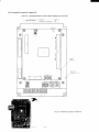
(2) CONI
1/0 signals
Here are descriptions
of 1/0 signals.
Table 3,11 1/0 signals
Symbol
Descriptions
Pin No
1-A i
CON I -B 1
CON
+24V
1/0
: Power source, or COM signal
Name
: +24V (power source)
Function : This signal shows that power is being supplied (+24V) (Power may
also be supplied from TM 1- 1.), or represents the COM signal in the
case of +24V common type.
CON I -A2
OV
CON1-B2
: Power source, or COM signal
1/0
: OV power source
Name
Function : This signal shows that power is being supplied (OV) (Power may
also be supplied from TM 1-2.), or represents the COM signal in th~
case of OV common type.
STA. NO()
CON1-A3
STA. NO1
CON1-B3
STA. N02
CON I -A4
STA. NO?I
CON 1-B4
STA. N04
CON I -AS
STA. N05
CON I-B5
STA. N06
—
CON 1-A6
STA. N07
CON I-B6
STA. NOX
CON I -A7
1/0
Name
: Input
: Command input of station number
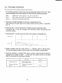
Function : Command a station number.
The command input is received at the moment the START signal
changes from OPEN [o CLOSED during either automatic
operation or setup operation. Hold the signal for over 10nlsec
after the START signal has changed from OPEN to CLOSED in
order for the signal to be read. Input a 9-bit binary (STA,NO():
LSB STA. NOX: MSB) code signal.
➤tl-t2—,
t I > omsec
–J
START OPEN
1/0
: Input
Name
: Operation command input
Function : Each operation begins with this signal CLOSED.
■ At Automatic
Operation
Station number is received at the moment the START signal changes
from OPEN to CLOSED, and the positioning operation is started. Its
speed is V 1 (parameter).
Hold CLOSED until [he operation completion
signal (COIN, COIN-A) is output. Changing to OPEN before the
START
..
CON I-B7
completion of indexing causes the machine to stop at the nearest
available station in the running direction. And COIN signal is output,
but COIN-A is not output.
■ At Manual Operation
The operation is started in the direction commanded
by the F/R signal
at the moment the START signal changes from OPEN to CLOSED. Its
speed is V2 (parameter). When the START signal is turned OPEN, the
machine stops at the nearest tivailable station in the running direction
and COIN signal is output. (COIN-A is not output. )
–lo-
Table 3.11 1/0 signals (Cent’d)
Symbol
Descriptions
Pin No.
■ Setup Operation
The current station number is received when the START signal c1
from OPEN to CLOSED, and COIN signal, COIN-A signal, and (
current station number received (POS. NO) are output.
■ At Zero-point
Return Operation
The zero-point return operation is started when the START signal
changes from OPEN to CLOSED. Hold the OFF signal until the
operation completion signal (COIN) is output. Its speed is V3, V,
(parameter).
9 Zero-point Offset Automatic Setup Operation
START
The zero-point offset automatic setup operation is started in the
direction set by the parameter setting when START signal change
from OPEN to CLOSED. Hold the CLOSED signal until the ope
completion signal (COIN) is output. Its speed is V5 (parameter)
CON 1-B7
■ Jog Operation
The jog operation is started in the direction set by F/R signal whe]
START signal changes from OPEN to CLOSED. Its speed is V6
(parameter). When START signal is turned to OPEN, it stops
simultaneously.
This stop position is not in the usual station posi{
and the COIN signal is not output, however, when the machine st
a station position, the COIN signal and station NO.(POS.NO.) ar~
output.
1/0
Name
: Input
: Direction command input
Function : Carries out the direction command of an operation.
This is valid only in the following operations:
Automatic operation (Only valid in the external direction
command mode).
Manual operation
Jog operation
This input is received at the moment the START signal changt
from OPEN to CLOSED. In order for the signal to be read, in
F/R signal before or at the same time as the START signal, an
for over 10msecs. It becomes CCW or CW when the signal is
changed to OPEN, while CW or CCW when it is changed to
CLOSED. Either may be switched by the parameter setting.
●
●
F/R
CON 1-AX
●
1/0
: Input
Name
: Operation mode command input
Funl ion : Carri s out the o eration m de that you command.
MODE6
CON I -B8
MODE I
CON 1-A9
MODE2
CON 1-B9
r
MODE 2
MODE I
MODE ()
OPEN
OPEN
OPEN
OPEN
OPEN
CLOSED
OPEN
CLOSED
OPEN
Ope.dtion mode
Jog operation
Setup c)peration
Zero-point return operation
OPEN
CLOSED
CLOSED
CLOSED
OPEN
OPEN
CLOSED
OPEN
CLOSED
CLOSED
CLOSED
OPEN
No mode
CLOSED
CLOSED
CLOSED
No mode
–11–
Zero-p[lint offset automatic setup o~ratinn
Automat]c operati[>n
Manual operation
Table 3.11 1/0 signals (Cent’d)
Symbol
Pin No.
Descriptions
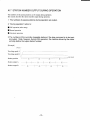
All modes are received at the moment the START signal changes from OPEN
to CLOSED.
In order for the signal to be read, input mode signal before or at
the same time as the START signal, and hold for over 10msec.
MODEO
CON 1-B8
MODE1
CON 1-A9
MODE’
CON1-B9
Ft’+t’+
MODE
~;;
; ,~j~
~
START OPEN
When the START signal changes to CLOSED, if the operation mode is set to
no mode, a “mode set error” is displayed.
1/0
: Input
Name
: Zero-point LS signal
Function : Zero-point
LS signal at zero-point return operation
■ At zero-opoint
return operation (CO- 14=()).
Detecting this signal changing from OPEN to CLOSED decelerates
V4 from V3. Then detecting the signal CLOSED to OPEN.
to
Move and position by the zero-point offset from the first Z-phase pulse.
This stopping position is zero-point. Fault occurs if point of the signal
ZRET-LS
changing CLOSED to OPEN and Z-phase pulse is closer than f] 20
PULSE. In this case, move zero-point 1.S.
CON I-A 10
■ At zero-point
return operation (CO- 14=1).
Detecting this signal changing from OPEN to CLOSED decelerates to
V4 from V3. Then detecting CLOSED
to OPEN, move and position as
zero-point offset preset. This stopping position is zero-point
*: Enab]es zero-point return operation if the signal CLOSED time
is over 1Omsec.
But might go over zero-point (after go over return to zero-point).
Because CLOSED time is too short.
EMG
CON1-B10
..
1/0
: Input
Name
: Emergency
stop signal
Function : Emergency stop is carried out when this signal is input in each
operation. The stop position is not the station position.
After stopping, the COIN signal and COIN-A signal are not
output. After an emergency stop, alarm status appears. To release
this alarm status, use the reset signal. After resetting, if the machine
stops at the station position, the COIN signal is output. If it does
not stop at the station position, the COIN signal is not output.
After resetting, the automatic/manual operation may be continued
without carrying out the zero-point return operation/setup operation,
Normally, input CLOSED signal for this signal. The system detects
OPEN, and carries out an emergency stop. With teaching operation
EMG signal is valid. Perform the teaching with CLOSED signal
input.
–12–
Table 3.11 1/0 signals (Cent’d)
J .-----
. ... ..- .
—-----
1/0
~..-..v
: Input
Name
: Servo ON signal
Function : Set this at CLOSED during operation.
During CLOSED status,
the motor drive is valid. When the signal is changed to OPEN,
SVON
the inverter output is shut-off instantaneously
results.
CON1-A1l
and coasting status
After servo is turned ON, automatic/manual
operation may be
continued without carrying out zero-point return operationlsetup
operation.
With teaching operation, SVON signal is valid.
JOG operation is executed by only CLOSED signal input.
1/0
: Input
Name
: Fault reset
Function : When the driver (X3000) or the positioning
controlling
portion
(point module) detects an error, alarm stop status is held.
<ESET
CON1-B1l
Signal to return to operation status after removing the cause.
Resets by changing the signal for OPEN to CLOSED to OPEN.
However, reset the SVON signal by OPEN signal input only whe
the alarm occurs in the driver X3000.
Reset cannot be executed i
SVON signal is CLOSED.
IULT. O
CON1-A12
lULT. 1
CON I-B12
: Input
Name
: Multiple-pattern
Function
: More than one operation can be selected by combining two bits.
CON1-A13
selection
MULT.O
OPEN
CLOSED
OPEN
CLOSEI
MULT. 1
OPEN
OPEN
CLOSED
CLOSEI
Vlo
V20
V30
V40
V50
V60
ACCO
KpO
tso
Vso
TLO
COINO
NEARO
Vspo
Kp20
Vll
V2 I
V31
V41
V51
V61
ACC 1
Kp 1
ts 1
Vs1
TL 1
COIN1
NEAR 1
Vsp1
Kp21
V12
V22
v3~
V42
V52
V62
ACC2
V13
V23
V33
V43
V53
V63
ACC3
KP3
ts3
VS3
TL3
COIN3
NEAR3
vsp3
Kp23
Automatic operation speed
Manual operation speed
High speed zero-point return
Low speed zero-point return
Zero-point offset automatic setup speed
Jog speed
Acceleration time
Positioning control constant
Software start time
Software start speed
Torque limit
Operation completion width
Positioning vicinity width
Soft stop speed
Soft stop Kp2
Parameter
..
COIN
1/0
Kp~
ts2
VS2
TL2
COIN2
NEAR2
vsp2
Kp22
setting is EO-nn for all.
1/0
: output
Name
: Operation completion
Function
:The system outputs the completion
-13-
signal
of each operation mode.
Table 3.11 1/0 signals (Cent’d)
Symbol
Descriptions
Pin No.
I
E Automatic Operation Mode
CLOSED is output at the completion of positioning to the
commanded station.
Action completion width is set by parameter.
When the same station as the current station is specified, the output
signal remains CLOSED, so confirm the action completions by
checking for the COIN signal 10msec after the input of the START
signal. Changing the START signal to OPEN during positioning
causes the controlled machine to position itself at the nearest
available station in the running direction.
■ Manual Operatoin Mode
The system finishes manual operation, and outputs CLOSED when
positioning and stopping the controlled machine at the nearest available
station in the running direction.
Action completion width is set by
parameter.
I
■ Setup Operation Mode
I
The system completes setup operation, and outputs CLOSED when
I
receiving the current station No.
During that time, OPEN is output (for 20msec), and then CLOSED
is output, so determine completion by checking that the signal is
COIN
changed from OPEN to CLOSED.
In setup mode, COIN-A signal is output in the same manner as COIN
CON1-A13
I
signal.
I
■ Zero-point Return Mode
I
The system outputs CLOSED at the completion of zero-point return.
After that, carry out setup operation.
Be aware, however, that in the case
of (CO- 15#0), the setup operation will be automatically y performed for the
value of (CO-15).
■ Zero-point Offset Automatic Setup Operation Mode
The system outputs CLOSED at the completion of zero-point offset
automatic setup operation.
I
■ Jog Operation Mode
The system outputs OPEN at the start of JOG operation mode.
Outputs CLOSED when the controlled machine is stopped at the
station. Outputs OPEN when the machine is not stopped at any
station.
*: After changing the START signal from OPEN to CLOSED, outputs
OPEN COIN signal within 5msec, and starts positioning action.
*: Immediately after turning the system ON, the OPEN COIN signal
is output.
I
COIN-A
CON1-B13
1/0
Name
: output
: Automatic positioning
signal
Function : The system outputs this signal at the completion
automatic operation.
-14.
completion
of positioning
in
Table 3.11 1/0 signals (Cent’d)
Symbol
Pin No.
Descriptions
■ Automatic
Operation Mode
CLOSED is output at the completion
commanded
station.
Completion
of positioning
at the
width is set by parameter.
When the same station as the current one is specified, the output
signal remains CLOSED (the same way as COIN signal).
Making START signal OPEN during positioning
causes the
machine to position itself at the nearest available station in the
running direction, however, in this case, CLOSED is not output, and
OPEN is held.
COIN-A
CON I-B13
■ Setup Operation
Mode
The system carries out the same output sequence as the COIN
signal.
*: After changing START signal from OPEN to CLOSED, Outputs
OPEN COIN-A
*: Always
outputs
*: immediately
signal within 5msec,
OPEN in operation
after turning
and starts positioning
action.
modes other than the above.
the system
ON, OPEN COIN-A
signal is
output.
1/0
: output
Name
: Positioning vicinity signal
Function : The system outputs CLOSED when the controlled machine
approaches the aimed station.
■ Automatic/Manual
Operation Mode
The system outputs when the controlled machine comes close to the
station to be positioned. The range of vicinity is set by parameter.
Use this signal when mechanically clamping just before positioning.
After changing the START signal from OPEN to CLOSED, OPEN
NEAR signal is output within 5msec, and positioning
NEAR
CON I-A14
action is
started.
■ Setup Operation
Mode
The system carries out the same output sequence as for the COIN
signal.
*: After changing START signal from OPEN to CLOSED, outputs
OPEN COIN-A signal within 5msec, and starts positioning
action.
*: Always outputs OPEN in operation modes other than the above.
*: Immediately
after turning
the system ON, the OPEN NEAR signal
is output.
1/0
: output
Name
: Zero speed signal
Function : The system outputs CLOSED when motor speed falls below zero
ZSPD
CON I-B14
speed (approximately 10r/min).
This output signal is output independently
status.
–15–
regardless of operatior
Table 3.11 1/0 signals (Cent’d)
Symbol
Descriptions
Pin No.
1/0
: output
: Error signal
Name
Function : The system outputs CLOSED when an alarm is detected at the
driver or the positioning controller. In this case, power is shut
down and the motor goes into zero-speed status. However, only
alarm signal in the driver X3000 is base-blocked. Alarm status is
held, and is released by reset signal.
Alarm indication
11
ndication
ALARM
CON I-A15
Contents of alarm
()
1
~
Alarm detected at the driver (Contents are indicated at driver side. )
PG failure (including wiring failure)
3
No setup opemtion after turning ON (Except in the ABS mode)
4
5
Zero-point LS not detected during Zen-point offset automatic setup operation
Zerc~-point LS not detected during zero-pofnt return
Emergency
stop
Undefined station number i~ specified.
6
7
Opemtion mode is not set properly.
Though zero-point offiet setup mode i$ in the parameter setup mode, ~ero-point
8
offset automatic setup opera(ion i~ specified.
9
A
Position error or zero-point LS (too close to Z-phfisc pulse pnsi(ion)
Zero-point offset amount is out of the allowable range,
b
(Other than 120 to 12000)
When the backlash cc~rrection is nut “f.)”.
o Zen-point
of’fset automatic setup opemtiun is specltled,
o Setup operation is specified without ~ero-point return.
The backlash correction is larger ( han the unit station pulses.
c
d
Blank
S[ation is not positioned in order of ~ta[ion No.
Memory storage error in the ABS mode
CPU error (including status OULt)l control )
*: Indication shows 7-segment numeric indicated on the point module
board.
*: Blinking indication is alarm status.
*: Steady lighting indication is status indication.
1/0
—
: output
Name
POS,NOO
CON1-B15
POS,NO1
CON1-A16
POS,N02
CON1-B16
POS,N03
CON1-A17
POS,N04
CON1-B17
POS,N05
CON1-A18
Pos,No6”’--
CON I-B18
POS,N07
CON1-A19
POS,N08
CON1-B19
: Current station number
Function : The system outputs the current station number.
The system outputs the 9-bit binary code signal (POS.NOO: LSB,
POS.N08: MSB).
■ At Automatic
Operation
The system outputs the station No. at which stopped when completing
the positioning to the specified station. During operation, the station
No. which can be stopped in operation direction is output. Also
outputs the station number when the START signal is changed to
OPEN during operation and the controlled machine is positioned and
stopped at the nearest available station in the operation direction.
■ At Manual Operation
The system outputs the station No. at which stopped when completing
the positioning to the arbitrary station. During positioning, station
number at which can be stopped in operation direction is output.
–16-
Table 3.11 1/0 signals (Cent’d)
Symbol
I
Pin No.
~e~rrinfions
—--- . .. ...
■ At Setup Operation
The system outputs the specified station number after completion
setup operation.
of the
POS,NOO
CON1-B15
POS,NO1
CON I-A16
*: After confirming
POS,N02
POS,N03
CON1-B16
CON1-A17
*: “()” is output after the system is turned ON, after zero-point return, and
COIN signal changing
OPEN+ CLOSED, receives this signal.
POS,N04
CON I-B17
after the zero-point offset automatic
POS,N05
CON1-A18
setup operation (CO- 15), the system outputs the value set to (CO- 15)
setup operation.
When automatic
POS,N06
CON1-B18
after completing
POS,N07
CON1-A19
POS,N08
CON1-B19
the zero-point return.
*: “()” is output during JOG operation and after an emergency
stop.
When the controlled machine is stopped at a station after JOG operation
and after resetting following an emergency
stop, the station number is
output.
1/0
: output
Name
A,BS.READY
CON1-A20
: Memory storage in ABS mode completed
Function : After turning ON the ABS.ST OPEN signal and stopping the motor
at the same time in the ABS mode, the system stores the current
position information into memory and outputs the completion
signal (CLOSED). Maintain the 24VDC power source until this
output turns to CLOSED. A special brake motor is required to use
the ABS mode.
1/0
(
OPT.
OUT()
CON 1-B20
: output
: Preliminary
Function :
—
Name
1/0
CON 1-A21
24V
CON I-B21
Name
Ov
: Power source, or COM signal
: +24 V(power source)
Function : This signal shows that power (+24V) is being supplied (Power may
also be supplied from TM 1- 1.), or represents the COM signal in the
case of +24V common.
1/0
CON 1-A22
CON 1-B22
output
: Power source, or COM signal
Name
: OV(power source)
Function : This signal shows that power (OV) is being supplied (Power may
also be supplied from TM 1-2.), or represents the COM signal in the
case of OV common.
1/0
: Input
Name
-.
ABS.ST
CON1-A23
: Memory storage command in ABS mode
Function : After detecting the change of this signal from CLOSED to OPEN
in the ABS mode, the system stops the motor and stores the position
information into memory when the motor is completely stopped.
Then the system outputs the ABS. READY CLOSED signal.
When the CLOSED input is detected for 0.5sec. or more after the
power is supplied, the position information memory is read and the
state before the power shutoff will be regained. The system then
outputs the ABS. READY OPEN signal. This will function only
in the ABS mode.
d
-17-
Table 3.11 1/0 signals (Cent’d)
Symbol
Pin No.
Descriptions
OPT.INO
CON1-B23
: Input
1/0
Name
: Preliminary input
Function :
NC
CON 1-A24
to
CON1-A25
1/0
: For future use
Name
:
Function :
..
–18–
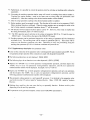
3.6 WIRING PRECAUTIONS
(1) Use twisted pair shielded cables for PG feedback circuit.
Cable length may be up to 10Om. For wiring, connect the cables in the shortest distance and cut
off the surplus. (Refer to Table 3.2.)
(2) For grounding cables, use as large size as possible.
Class 3 grounding ( 10OQ or less) is recommended.
Grounding must be provided at one point. If motor is insulated between machines, use another
grounding method to ground the motor.
(3) To prevent noise malfunction, take the following actions:
“ Locate Juspoint III or 1/0 reference setter precisely.
Provide a surge absorbing circuit to relay coils, magnetic contractors, solenoids, etc.
Separate main circuits (high-voltage circuits such as AC lines or motor power lines) and signal
circuits more than 30cm. Do not run them in the same duct or bundle them together.
Provide a noise filter to the power supply or input circuits when the power supply is shared with
electrical welders or discharging machines, or when there is a high-frequency noise generating
source near the unit.
Use shielded cable for 1/0 signal wiring and the shielding treatment should be preformed at
TM 1-2 (OV) terminal of the point module.
●
●
●
●
(4) Radio Frequency Interference Preventive
No preventive actions for radio frequency
industrial device. Therefore, if it is used
causes any problems, provide a line filter
Actions (R.F.1)
interference are provided to Juspoint ~ since it is an
in a residential area or radio frequency interference
at the main circuit power supply input side.
(5) Since cable cores used for PG feedback circuit or signal circuits are very thin, do not apply
bending force or tension force to the cables.
–19–
4. DESCRIPTION
OF OPERATIONS
4.1 FUNDAMENTAL
OPERATIONS
Fig. 4.1 shows the flowchart of fundamental operations.
After turning the system ON, select the desired operation mode.
r
1
I
1
+
e“-Zero-point return
II
YES
I
1
1
Zero-point
Setup
1
I
I
Turning ON (Other than ABS mode)
return
Manual
operation
->
Automatic operation
[
I
I
I
I
Setup*
I
I
t
When (CO- 15=0), the setup operation is necessary after zero-point return.
In the case of (CO- 15#0), no setup operation is requested since the system executes the setup
operation for (CO- 15) atuomatically~
Fig. 4.1 Flowchart of Fundamental
Operations
Table 4.1 Setting of Operation Mode
Operation mode
MODE2
MODE I
MODE()
START
OPEN
OPEN
OPEN
OPEN + CLOSED
JOG opemtion
OPEN
OPEN
CLOSED
OPEN + CLOSED
Setup operation
CLOSED
OPEN
OPEN + CLOSED
Zero-point return
OPEN
CLOSED
CLOSED
OPEN + CLOSED
Zero-point offset amount automatic setup operation
CLOSED
OPEN
OPEN
OPEN + CLOSED
Automa(ic
CLOSED
OPEN
CLOSED
OPEN + CLOSED
Manual operation
OPEN
. .
operation
No applicable modes
Other than the above
–20-
4.2 SETUP
■
Function
■
Sequence
r
The system sets the station number of the controlled machine currently stopped.
To carry out setup operation, it is necessary that the machine be stopped at any one of
the station positions and mechanically clamped. Otherwise, carry out setup operation
after zero-point return.
When (CO- 15=0), the setup operation is necessary after zero-point return. In case of
(CO- 15#0), no setup operation is requested.
Automatic/manual operation without setup operation after turning the system ON
results in an alarm (exept in the ABS mode).
If the backlash correction is not “O”, always carry out zero-point return before setup
operation (except in the ABS mode).
Fig. 4.2 shows the sequence of setup.
1
Input the current station number
Select setup operation mode.
L
I
Input START
STA.NOO to STA.N08
MODEO to MODE2
signal after the above
START
OPEN
+ CLOSED
+
OPEN COIN and OPEN NEAR signals are
output within 5msec from START signal.
+
COIN CLOSED or OPEN+
OPEN
NEAR CLOSED or OPEN + OPEN
I
I
E
CLOSED NEAR, CLOSED COIN, CLOSED
COIN-A signals are output within 20msec.
-.
NEAR, COIN, COIN-A
OPEN + CLOSED
I
Station number (POS.NOO to POS.N08)
Collate it with the set station number.
is output at completion.
Fig. 4.2 Sequence of Setup Operation
■
Time chart
SVON
Fig. 4.3 shows the setup time chart.
OPEN —
MODE
STA. NO
..
START
POS.
1
I
OpEN ~
NO
Fig. 4.3 Time Chart of Setup Operation
-21-
I
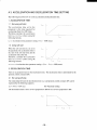
4.3 ZERO-POINT
■
Function
The
RETURN OPERATION
system carries out positioning of the machine and stops it at the zero-point.
Return to zero-point used zero-point LS signal.
Detecting start signal changing from OPEN to CLOSED.
Start zero-point return operation direction by CO-05 speed by V3.
Detecting zero-point LS signal changing from OPEN to CLOSED decelerate to V4.
Then detecting zero-point LS signal changes CLOSED to OPEN.
●
●
■
Sequence
At zero-point return operation O (CO-14=0)
Move and position by the zero-point offset preset from the first Z-phase pulse of PG.
At zero-point return operation 1 (CO-14=1)
Move and position by the zero-point offset preset.
Running speed V3, V4 is set by parameter (EO-20 to -23, EO-30 to -33).
Fig. 4.4 shows the sequence of zero-point return operation.
Input of zero-point return mode
MODEO to MODE2
J
Input of START signal after the above
START OPEN + CLOSED
i
1
I
COIN signal is output within 5msec,
and zero-point return starts.
COIN OPEN or CLOSED + OPEN
Detection of zero-point LS signal,
deceleration, and stopping at zero-point.
COIN OPEN + CLOSED
Fig. 4.4 Sequence of Zero-point
■
Time chart
SVON
1
Return Operation
Fig. 4.5 shows the time chart of zero-point return operation.
OPEN
MODE
START
OPEN
ZRET - LS
OPEN ~
CO-14=1
CO-14=0
PG
.r...r~~fs~’.~..
A, B“pdse
Z pulse
n n n
.“””””””~OpEN~cLOsED-
COIN
SPEED
~v’~vl—.
Fig. 4.5 Time Chart of Zero-point
–22-
Return Operation
–
4.4 ZERO-POINT
OFFSET AUTOMATIC
SETUP OPERATION
■
Function
The system automatically sets zero-point offset.
When it is possible to turn ON the system with the machine stopped at zero-point
(clamped status), this operation is possible. When it is not possible to carry out zeropoint offset setup operation, set zero offset by parameter.
Adjust the zero-point LS position so that the offset becomes within the allowable
range (range set by parameter CO-10).
Direction command is set by parameter. Set the parameter in the direction of zeropoint LS (normally the opposite direction of zero-point return.) When the backlash
correction is not “O”, it is not possible to carry out zero-point offset setup operation.
Running speed V5 is set by parameter (EO-40 to -43).
■
Sequence
Fig. 4.6 shows the sequence of zero-point offset setup operation.
L---
Input of zerc)-point
““~.
Input of START
1-..
MODEO to MODE2
.~
offset setup mode
-__”
START
signal :~fter the above
1
1
COIN signal is output within 5msec,
and auto setup operation starts.
L-.
Detection of zero-point LS signal.
And zerc>-point offset is automz~tically
COIN OPEN or CLOSED -
set.
OPEN
—A
r-
+-
Fig. 4.6 Sequence of Zero-point
-.
COIN OPEN + CLOSED
1
Offset Automatic Setup Operation
Time Chart
SVON
CLOSED
——
MODE
OPEN
START
Z pulse
A, B pulse
—
n
co
co
COIN
OPEN
n
r
~~
-.
ZRET - LS
1
I
Moving in reverse after detection on zero-point
LS signal, and stopping at the original position.
PG
PG
J
J
~-–
■
OPEN + CLOSED
14=0
14=1
F
f
n
r
Offset
+J
Offset
—
~Op~N~cLOsEm
SPEED
~v5~
Fig. 4.7 Time Chart of Zero-point Offset Automatic Setup Operation
-23-
n
4.5 AUTOMATIC
Function
OPERATION
The system moves the controlled machine to the station of the commanded number,
positions it and stops it there.
In the case of a rotating axis, the shortest path control which determines the shorter
distance direction is used.
The direction can be fixed or commanded externally.
When START signal is changed from CLOSED to OPEN during automatic
operation, the machine is positioned and stopped temporarily y at the nearest station in
the running direction at that moment. Then COIN signal is output. (COIN-A signal
is not output.) From this status, any operation mode is possible to use.
Running speed V 1 is set by parameter (EO-00 to -03).
Sequence
Fig. 4.8 shows the sequence of automatic operation.
Input automatic operation mode
Input station command value
I
MODE() to MODE
STA.NOO to STA.N08
Input START signal after the above
START
OPEN + CLOSED
+
I
COIN and COIN-A signals are output within
5msec, and automatic operation starts.
Time Chart
I
COIN-N, COIN CLOSED + OPEN
Fig. 4.9 shows the time chart of automatic operation.
CLOSED
SVON
—
MODE
STA. NO
START OPEN
COIN-A
COIN CLOSED
~–—–.–.
NEAR CLOSED
POS.
NO
\
/
Fig. 4.9 Time Chart of Automatic Operation
-24-
I
4.6 MANUAL OPERATION
■
Function
The system positions the machine and stops at each station by manual operation.
Select manual mode and direction and make START signal CLOSED, and operation
will start. When making START signal OPEN, the machine will be positioned and
stopped at the nearest available station in the operation direction.
Running speed V2 is set by parameter (EO- 10 to - 13).
■ Sequence
I
Fig. 4.10 shows the sequence of manual operation.
Input of manual
MODEO to MODE2 F/R
mode and direction
operation
+
I
I
START
Input of START signal after the above
OPEN + CLOSED
+
I
COIN and NEAR signals are output within
5msec, and manual operation starts.
I
)
COIN, NEAR
CLOSED + OPEN
I
1
START CLOSED + OPEN
START signal is stopped.
i
I
POS. NO, NEAR, COIN OPEN+
Manual operation completion
Note: After start of operation,
COIN-A signal is output OPEN, and continues to be output even after completion of
opemt ion.
Fig. 4.10 Sequence of Manual Operation
■ Time Chart
Fig. 4.11 shows the time chart of manual operation.
F/R
MODE
OPEN
START
COIN
CLOSEI)
NEAR
CLOSED
~~
..
POS.
SPEED
CLOSED
NO
_/-—v2~
Fig. 4.11 Time Chart of Manual Operation
-25-
I
4.7 EMERGENCY
■
Function
STOP OPERATION
When emergency stop signal (EMG) is OPENED during any operation, emergency
stop is carried out. Normally, the stop position is not a station. (deceleration stop)
After an emergency stop, output is stopped, and alarm status appears.
perform after reset.
To release this,
After an emergency stop, COIN, COIN-A, and NEAR are output OPENED. When
the machine is stopped at any station after resetting, COIN, NEAR signals are output
CLOSE. COIN-A is output CLOSED.
After an emergency stop, the station position output indicates “O”.
When the machine is stopped at any station after resetting an emergency stop, that
station number is output.
When emergency stop operation is performed after a setup operation, there is no need
for zero-point return operation/setup operation after reset.
Manual/automatic operation is possible without any preparation.
4.8 JOG OPERATION
■ Function
The system carries out a JOG operation.
After selecting JOG operation mode and F/R signal, changing the START signal from
OPEN to CLOSED causes operation to start in the commanded direction.
And the machine stops at the same time the START signal is changed to OPEN.
Normally the stop position is not a station.
During JOG operation, COIN, COIN-A, NEAR signals are output OPENED at the
same time as the start of operation, and OPEN signals are output even after
completion.
However, in the case of stopping at a station, COIN and NEAR signals are output
CLOSE. COIN-A is output OPEN.
During JOG operation, the station position output indicates “O” at the same time as
the start of operation and even after stopping, indicates “O.”.
When stopping at a station, the number of the station is output.
When carrying out a JOG operation after setup, there is no need for a zero-point
return operation or setup operation.
Manual/automatic operation is possible without any preparation.
Running speed V6 is set by parameter (EO-50 to -53).
..
-26-
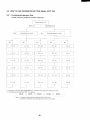
5. PARAMETER
5.1 PARAMETER
SE~lNG
/ MONITORING
SETTING
Parameters to be used for station indexing control are shown in the table below.
Perform parameter setting while the motor is stopped.
Table 5.1 List of Parameters
Cn-NO
Co-oo
Co-ol
CO-02
CO-03
CO-04
CO-OS
C()-06
CO-07
CO-08
CO-09
co- Io
co- 11
co- 12
co- 13
co- 14
co- I5
CO-16
co- I7
co- 1x
d{)-02
cio-03°
do-45
EO-()()-03
E()-10-13
EO-’2O-23
EO-30-33
EO-40-43
EO-50-53
EO-60-63
EO-70-73
EO-80-83
EO-90-93
E()-AO-A3
EO-bO-b3
EO-CO-~
EO-dO-d3
EO-EO-E3
Function Name
Lower Limit
Number of stations
Rotational axis/linear axis
Unit station pulses
Rotation direction switching
O-point offset automatic setup
O-point return direction
Direction for CO-04
Gear ratio A
Gear ratio B
ABS mode
()-point offfet
Rotational axis direction
Parameter setting permission
Backlash correction
()-point return mode
Number of automatic setup
Unit PG pulses
Kp gain during stop (Kp3)
Control width for C()-17
Upper Limit
Unit
Initial Vatue
2
o
40
o
o
o
o
1
1
o
I20
o
o
o
o
o
o
10
0
511
4
960000
1
1
1
1
Pulsesbetweenstatiorr~( I-2)
Pttlse\ be[ween stations (2-3) or ( 1-3)
Pulse$ between stations (X-X) or ( l-X)
Pulses between stations (44-45) or ( 1-45)
40
40
40
40
96000000
96000000
96000000
96000000
PULS
PULS
PULS
PULS
4000
4000
4000
4000
Automatic operation speed (V 1O-V13)
Marrttti o~ration s~ed (V20-V23)
High speed O-point return (V30-V33)
Low speed O-point return (V40-V43)
Offset setting speed (V50-V53)
JOG speed (V60-V63)
Acceleration time (ACC()-ACC3)
Position control gain (KpO-Kp3)
Sofi-starttime (tsO-Ls3)
Sofi-srarfs@ (vs@vs3)
Torque limit value (TLO-TL3)
In-position width (COINO-C01N3)
Near-position width (NEARO-NEAR3)
Speed range for soft-stop (VspO-Vsp3)
Kp gain for soft-stop (Kp20-Kp23)
10
10
10
10
10
10
10
10
o
o
30
8
8
o
10
1800
1800
1800
1800
1800
i 800
5000
I000
99
99
300
80000
80000
1800
1000
rfmin
r/m in
r/m in
r/min
r/m in
r/m in
msec
0.1/s
msec
r/rein
%
PULS
PULS
r/rein
0.1/s
500
500
500
50
50
50
100
I00
o
o
200
20
400
PULS
8
0
4000
0
0
0
1
40000
40000
2
40000
3
1
80000
I
511
1
1000
I00
I
1
0
400
PULS
0
0
o
o
0
0
25
PULS
0,1/s
PULS
20
N(]tes :1. Attach or detach the digital operator (JVOP- I~) whtle the power ii turned OFF.
2. Any pos!tloll]ng operation is possible with the digital o~rator (J VOP- t M)) connected, however, parameters cannot be set during o~ration.
(Parameters can be set only white Juspoint D is not operating.)
3. Parameters out of the upper or the lower limit cannot be set. In this case, tbe upper or the lower limit will be set.
4. When 0 -pint [>ff\et automatic setup is selected and the O-point offset is out of tbe upper timit or the tower tim]t, an error occurs.
–27-
o
100
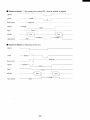
Table 5.2 Parameter Functions
Name
Range
Function
Co-oo
: Number of stations
: 2to511 (unit: 1, initial value: 8)
: Set the number of svations to be indexed.
Station position command (STA. NO O to 8) larger than the set number of
stations will result in an error.
Example 1 : In the case of 12-face indexing of rotational axis, set [ 12].
Example 2: In the case of 2-point indexing of linear axis, set [2].
Name
: Rotational axisflinear axis
Range
:0, 1,2,3
Function
o
: Set whether rotational axis or linear axis is to be indexed.
:Rotational axis (Uniform unit station pulses)
1
: Linear axis (Uniform unit station pulses)
2
: Rotational axis (Uniform unit and fractional unit station pulses)
: Linear axis (Arbitrary unit station pulses : incremental setting)
co-o 1
3
4
or 4 (unit: initial value: O)
: Linear axis (Arbitrary unit station pulses : absolute coordinate
setting)
In case of [CO-01=4], pulse setting by teaching operation is possible.
Name
: Unit station pulses
Range
Function
:40 to 960,000 (unit: 1, initial value:4000)
: Set the distance between respective stations in PC pulse units (multiples of 4).
Station distance set up to 240 rotations motor axis/station.
This parameter is valid only for [C()-O1=0, 1].
Pulses between stations are as shown below.
CO-02
~CO-02 is valid when CO-O1=0.
. CO-02 is valid when CO-01=1.
. CO-07 and CO-08 are valid when CO-01=2.
. dO-02 to dO-45 are valid when CO-O1=3.
dO-02 to dO-45 are valid when CO-O1=4.
Name
: Motor rotational direction switching
Range
:0 or I (unit: initial value: O)
Function
: Set the rotational direction of the motor.
Set the rotational direction in relation to the directional command signal (F/R) of
the control sequence input. Also set the sequence of the station numbers.
Example 1: In the case of [0]: Motor rotates CCW (viewed from the load side) when F/R
signal is OPEN. Or, the station number increases in the CCW
direction.
CO-03
Example 2: In the case of i 1]:Motor rotates CW f.viewed from the load side) when F/R
signal is OPEN. Or, the station number increases in the CW
direction.
-
Name
: Zero-point offset automatic setup mode
Range
:0 or 1 (unit: initial value: O)
Function
: Set using the parameter (CO-10) or zero-point offset automatic setup operation tf
set the zero-point offset.
CO-04
Example
I : In the case of [01: Setting by parameter is selected, Executing zero-Point offset
setup operation with this setting will result in an error.
Example 2: in the case of [ I ]: Setting by zero-point offset automatic setup operation is
selected.
–28-
Table 5.2 Parameter
CO-05
Functions (Cent’d)
Name
: Zero-point return direction
Range
:0 or 1 (unit: initial value: O)
Function
: Set the direction of the zero-point return.
Example 1 : In the case of [0]: Zero-point return will be carried out in the same direction as
when the F/R signal is changed to OPEN.
Example 2: In the case of [ 1]: Zero-point return will be carried out in the same direction as
when the F/R signal is changed to CLOSED.
CO-06
Name
: Zero-point offset automatic setup operation direction
Range
:0 or 1 (unit: initial value: O)
Function
: Set the direction of the zero-point offset automatic setup.
Normally, set in the opposite direction of the zero-point return.
Example 1: In the case of [0]: Zero-point offset automatic setup will be carried out in the
same direction as when the F/R signal is changed to OPEN.
Example 2: In the case of [ 1]: Zero-point offset automatic setup will be carried out in the
same direction as when the F/R signal is changed to CLOSED.
CO-07
Name
: Gear ratio B/A
Range
:1 to 40000 (unit: 1, initial value: 1)
Function
: To be used when the unit station pulse is fractional.
Set “A” or “B” of the gear ratio (B/A)
CO-07: Gear ratio A
CO-08
CO-08: Gear ratio B
Example 1: When the gear ratiois“1/179”
(decelerating),
Example 2: When the gear ratio is “55/1 9“ (accelerating),
Name
: ABS mode
Range
:0, 1,2 (unit: initial value: O)
Function
O
: Set the ABS mode.
: The ABS mode is not used.
1
: ABS mode [1]. All the position information
stored in the nonvolatile memory.
CO-09
2
A=179 and B= 1
A= 19 and B=55
before turning OFF the power is
A specially designed brake motor is required.
Control equivalent to an absolute value PG is possible.
: ABS mode [2]. Only the information of the stations stopped before turning OFF
the power is stored in the nonvolatile memory. Since the amount the motor
moves while the power is OFF will remain as an error, a mechanical clamp (e. g.
clamp pin insertion) must be provided.
required.
A specially designed brake motor is not
Set “O” for the backlash correction (CO- 13).
Name
Range
: Zero-point offset
:120 to 40000
(unit: 1, initial value:400)
Function
: This is used when setting the zero-point offset by parameter.
..
co-10
Set in PG pulse
units (multiples of 4).
Additionally, in order to make the zero-point return operation stable, adjust the
motor axis so that setting can be made within the upper limit and the lower limit.
(In the case of zero-point offset automatic setup mode, exceeding the above
rang will also result in an error.)
-29-
Table 5.2 Parameter Functions (Cent’d)
Name
: Rotational axis direction command mode
Range
:0,1, 2,3 (unit: initial value: O)
Function
: Set the direction when executing automatic operation of rotational axis.
O
: Positioning
is perfomed in the shorter distance direction.
1
: Positioning
is performed in the same direction as that when the F/R signal turns
co-11
OPEN.
2
: Positioning
is performed in the same direction as that when the F/R signal turns
CLOSED.
3
: Positioning
is performed according to the external command (F/R signal).
Name
: Parameter setting permission
Range
:0 or 1 (unit: initial value: O)
Function
: This parameter allows or prohibits setting of parameters. JOG operation by
teaching can be performed, but the position setting [write to (dO- XX)] is not possible
co-12
o :All parameters can be set.
1
: Parameters cannot be set or initialized.
setting.
To be used when prohibiting
parameter
When this parameter is set to CO-12=1, parameter initialization
cannot
be performed.
Name
: Backlash correction
Range
:0 to 80000 PULSES
(unit: 1, initial value: O)
Function
: Set the backlash correction in PG pulse units (multiples of 4). The direction of
correction is opposite to the zero-point return.
When the backlash correction is set to a value other than “O”, be sure to carry out
co-13
the zero-point return after turning the system ON. (except in the ABS mode 1)
Commanding the setup operation without the zero-point return will result in an error.
Also when the backlash correction is set to a value other than “O”, it is not
possible to carry out the zero-point automatic setup operation.
Name
: Zero-point return operation select.
Range
:0 or 1 (unit: initial value: O)
Select operation mode
co-14
O : Zero-point return (return mode O) used with Z phase pulse.
1: Zero-point return (return mode 1) without Z phase pulse.
Name
: Automatic setup number
Range
:0-511 (unit: 1, initial value:O)
Function
: The setup operation will be automatically
co-15
performed at the end of the zero-point
return operation for the number set in [CO-15].
In the case of [CO- 15=0], the setup operation will not be performed automatically
the setup operation is required after the zero-point return.
Also, the setup operation is required after the power supply (except in the ABS mode
..
Name
: PG pulses
Range
:0 or 1 (unit: 1, initial value: O)
Function
CO- 16
: Set the PG pulses of the motor.
0:1000
1:1024
pulses/rev.
pulses/rev.
Two types of PG pulses can be selected.
Normally set “O”. If this setting does
not agree with the motor pulses, an alarm (alarm 1) will be output.
-30-
Table 5.2 Parameter Functions (Cent’d)
co-17
Name
: Kp gain during stop (Kp3)
Range
Function
:10-1000
(unit: 1, initial value: 25)
: Set the value of position control proportional gain for the range set by [CO- 18].
Normally, set a value smaller than Kp [EO-7n]. If the setting of Kp3 is larger thar
Kp, the value of Kp is assumed.
Name
: Control width for CO- 17
Range
: ()- 100 (unit: 1, initial value: 20)
Function
: Set the range of pulses controlled by Kp3.
In the set range of pulses, Kp [EO-7n] is switched to Kp3 for position control.
C()- 18
Once the control is switched to Kp3, it will be held until the operation is started
next (SATRT signal changing from OPEN to CLOSED).
In the state “O”, the position is controlled by the value of Kp3.
In the case of [CO- 18=0], the Kp3 control will not be executed.
Position will
always be controlled by Kp [CO-7n].
Name
Range
: Section ( 1-2) Arbitrary station pulses
:40-96000000 (unit: 1, initial value: 4000)
Function
: Set the station pulses for the section ( I -2) for the linear axis.
In the case of [CO-01 =3], set the pulses of section (1 -2) in units of PG pulses
(multiples of 4).
dO-02
In the case of [CO-01 =4], set the pulses of section (1 -2) in units of PG pulses
(multiples of 4).
In the case of [C()-OI=4], this parameter can be set automatically
Furthermore,
by teaching.
setting after teaching or teaching after setting are also possible.
.—
Name
Range
Function
: Section (2-3) or ( I-3) Arbitrary station pulses
:40-96000000” (unit: 1, initial value: 4000)
: Set the station pulses for the section (2-3) or ( 1-3) for the linear axis.
In the case of [CO-01 =3], set the pulses of section (2-3) in units of PC pulses
(multiples of 4).
dO-03
In the case of [CO-O1=4], set the pulses of section ( 1-3) in units of PG pulses
(multiples of 4).
In the case of [CO-O1=4], this parameter can be set automatically
Furthermore,
by teaching.
setting after teaching or teaching after setting is also possible.
—
Name
-.
Range
: Section (44-45) or ( 1-45) Arbitrary station pulses
:40-96000000 (unit: 1, initial value: 4000)
Function
: Set the station pulses for the section (44-45) or ( 1-45) for the linear axis.
In the case of [CO-O1=3], set the pulses of section (44-45) in units of PG pulses
dO-45
(multiples of 4).
In the case of [CO-O1=41, set the pulses of section (1-45) in units of PG pulses
(multiples of 4).
In the case of [CO-O1=4], this parameter can be set automatically
Furthermore,
by teaching.
setting after teaching or teaching after setting is also possible.
-31-
Table 5.2 Parameter Functions (Cent’d)
EO-00
EO-O1
EO-02
Name
Range
Function
: Automatic operation speed (V 1 n)
:10 to 1800 r/rein (unit: 1, initial value: 500)
: Set the running speed (V 1 n) for automatic operation.
EO-00 : 1st automatic operation runnning speed (V 1 O)
EO-O1: 2nd automatic operation runnning speed (V 1 1)
EO-02 : 3rd automatic operation runnning speed (Vl 2)
EO-03 : 4th automatic operation runnning speed (V 1 3)
Name
Range
Function
: Manual operation speed (V2 n)
:10 to 1800 r/rein (unit: 1, initial value: 500)
: Set the running speed (V2 n) for manual operation.
EO- 10: 1st manual operation running speed (V2 O)
EO- 11: 2nd manual operation running speed (V2 1)
EO- 12: 3rd manual operation running speed(V22)
EO- 13: 4th manual operation running speed (V2 3)
Name
Range
Function
: Zero-point return high speed (V3 n)
: 10 to 1800 r/rein (unit: I, initial value: 500)
: Set the high speed (V3 n) for zero-point return.
EO-20 : 1st high speed zero-point return (V3 O)
EO-21 : 2nd high speed zero-point return (V3 1)
EO-22 : 3rd high speed zero-point return (V3 2)
EO-23 : 4th high speed zero-point return (V3 3)
Name
Range
Function
: Zero-point return low speed (V4 n)
:10 to 1800 r/rein (unit: 1, initial value: 50)
: Set the low speed (V4 n) for zero-point return.
EO-20 : 1st low speed zero-point return (V4 O)
EO-21 : 2nd low speed zero-point return (V4 I )
EO-22 : 3rd low speed zero-point return (V42)
EO-23 : 4th low speed zero-point return (V4 3)
Name
Range
Function
: Zero-point offset automatic setup speed (V5 n)
:10 to 1800 r/rein (unit: 1, initial value: 50)
: Set the running speed (V5 n) of zero-point offset automatic setup.
EO-40 : 1st low speed zero-point return (V5 O)
EO-41 : 2nd low speed zero-point return (V5 I )
EO-42 : 3rd low speed zero-point return (V5 2)
EO-43 : 4th low speed zero-point return (V5 3)
Name
Range
Function
: Jog speed (V6 n)
:10 to 1800 r/rein (unit: I, initial value: 50)
: Set the running speed othe JOG operation (V6 n)
EO-50 : 1st low speed zero-point return (V6 ())
EO-51 : 2nd low speed zero-point return (V6 I)
EO-52 : 3rd low speed zero-point return (V62)
EO-53 : 4th low speed zero-point return (V6 3)
Name
Range
Function
: Acceleration time (ACC n)
:10 to 5000 msec (unit: 1, initial value: 100)
: Set the time required to accelerate from zero speed to maximum speed
( 1800 r/rein)
EO-60 : 1st acceleration time (ACC O)
EO-61 : 2nd acceleration time (ACC I )
EO-62 : 3rd acceleration time (ACC 2)
EO-63 : 4th acceleration time (ACC 3)
EO-03
EO- 10
EO- 11
EO- 12
EO- 13
EO-20
EO-2 I
EO-22
EO-23
EO-30
EO-31
EO-32
EO-33
EO-40
EO-41
EO-42
EO-43
EO-50
EO-51
EO-52
EO-53
‘“
EO-60
EO-61
EO-62
EO-63
-32-
Table 5.2 Parameter Functions (Cent’d)
EO-70
Name
: Position control proportion gain (Kp n: unit O.l/see)
Range
:1 to 1000 (unit: 1, initial value: 100)
Function
: Set the proportional
gain of the position loop.
EO-71
EO-70:
EO-72
EO-71 : 2nd position control proportional
gain (KP 1)
EO-73
EO-72 : 3rd position control proportional
gain (KP 2)
EO-73 : 4th position control proportional
gain (KP 3)
EO-80
lstposition
control proportional
Name
: Soft-start time at starting (ts n)
Range
:0 to 99 msec (unit: 1, initial value: O)
Function
: Set the time to soft-start at starting (ts n).
gain (KPO)
EO-81
EO-80 : 1st soft-start time upon starting (ts O)
EO-82
EO-81 : 2nd soft-start time upon starting (ts 1)
EO-83
EO-82 : 3rd soft-start time upon starting (ts 2)
EO-83 : 4th soft-start time upon starting (ts 3)
Name
Range
: Soft-start speed at starting (Vs n)
:0 to 99 r/rein (unit: 1, initial value: O)
Function
: The speed will reach the speed at the soft-start time (EO-8n) at the above Sti
See the chart below
EO-90 : 1st soft-start speed upon starting (Vs O)
EO-91 : 2nd soft-start speed upon starting (Vs 1)
EO-90
EO-92 : 3rd soft-start speed upon starting (Vs 2)
EO-91
EO-93 : 4th soft-start speed upon starting (Vs 3)
EO-92
EO-93
Speed
:’lJ—\>
EO-8n
Name
Time (ins)
: Torque limit value (TL n)
Range
:30 to 300% (unit: 1, initial value: 200)
Function
: Set the torque limit value (TL n) of the driver (X3000).
EO-AO : 1st torque limit value (TL O)
EO-A I : 2nd torque limit value (TL 1)
EO-A2 : 3rd torque limit value (TL 2)
EO-AO
EO-A3 : 4th torque limit value (TL 3)
EO-A I
100 (Y.) is the motor’s rated torque value. The deceleration
EO-A2.
emergency
EO-A3
by this torque value.
time in JOG,
stop, zero-point return, zero-point offset automatic setup is determined
Overrun may occur in manual/automatic
operation owing to the Kp value (EO-7n)
and torque limit value (EO-An). In that case, make the Kp a smaller value or
make the torque limit a larger value.
-33-
Table 5.2 Parameter Functions (Cent’d)
Name
Range
Function
: Operation completion width (COIN n, COIN-A n output width)
:8 to 80000 PULSES (unit: 1, initial value: 20)
: Set the allowable position error range (error between the aimed position and the
current position) for outputting COIN and COIN-A signals. Set in PG pulse unit
(multiples of 4). When the machine reaches the allowable range, the COIN/
COIN-A will be CLOSED and when the machine moves out of the allowable
range, the COIN/COIN-A will be OPEN again.
EO-bO : 1st operation completion width (COIN O, COIN-A O)
EO-bl : 2nd operation completion width (COIN 1, COIN-A 1)
EO-b2 : 3rd operation completion width (COIN 2, COIN-A 2)
EO-b3 : 4th operation completion width (COIN 3, COIN-A 3)
Name
Range
Function
: Positioning vicinity width (NEAR n output width)
:8 to 80000 PULSES (unit: 1, initial value: 400)
: Set the allowable position error range (error between the aimed position and the
current position) for outputting the NEAR signal. Set in PG pulses (multiples of 4
When the machine reaches the allowable range, the NEAR signal will be
CLOSED and when the machine moves out of the allowable range, the NEAR
signal will be OPEN again.
EO-CO : 1st near positioning width (NEAR O)
EO-C 1: 2nd near positioning width (NEAR 1)
EO-C2 : 3rd near positioning width (NEAR 2)
EO-C3 : 4th near positioning width (NEAR 3)
Name
Range
Function
: Soft stop speed (Vspn)
:0 to 1800 r/rein. (unit: 1, initial value: O)
: Set the speed at which the soft stop is to be started at the time of deceleration.
When the speed is decelerated to the setting Vspn, the position control
proportional gain Kpn [EO-7n] will be switched to Kp2n [EO-En].
EO-dO : 1st soft stop speed (Vsp O)
EO-dl : 2nd soft stop speed (Vsp 1)
EO-d2 : 3rd soft stop speed (Vsp 2)
EO-d3 : 4th soft stop speed (Vsp 3)
Name
Range
Function
: Soft stop Kp2
:10 to 1000 r/rein. (unit: 1, initial value: 100)
: Set the position control proportional gain for the soft stop.
Be sure to set a value smaller than the position control proportional gain used
before the soft stop (i.e. Kpn [EO-7n]). If a larger value is set, the same value as
Kpn will be used.
EO-EO : 1st soft stop Kp2 (Kp2 O)
EO-E1 : 2nd soft stop Kp2 (Kp2 1)
EO-E2 : 3rd soft stopKp2(Kp22)
EO-E3 : 4th soft stopKp2(Kp23)
EO-bO
EO-b 1
EO-b2
EO-b3
EO-CO
EO-C 1
EO-C2
EO-C3
EO-dO
EO-d 1
EO-d2
EO-d3
EO-EO
EO-E1
EO-E2
Speed A
(r/rein)
EO-E3
..
Vsp n (EO-dn) -----------------Kp2 n [EO-En]
>
Time (t)
Notes :1 The soft stop function will make the deceleration time longer, thus making the positioning time
(indexing time) longer.
The smaller the value of Kp2n or the larger the value of Vspn, the longer the positioning time
(indexing time) will be.
2 When a small value is set for Kp2n, the servo lock response for stopping will take a longer time. In
case an external force applies at the time of stopping, restoration to the zero position will take longer,
-34-
5.2 OPERATION
STATUS MONITOR
Table 5.3 shows the list of operation statuses to be monitored. Monitor the operation status while the
system is at a standstill. Monitoring cannot be carried out during operation.
Table
Un-No
5.3 List of Operation Statuses to be Monitored
Description
Name
Input signal block A
Input signal block B
Sequence input signal status CON 1-A3 to B9
Sequence input signal status CON I -A1O to B 12
A 23 to B23
UO-04
Output signal block A
Output signal block B
Station number command
Sequence output signal status CON 1-A 13 to B 19
Sequence output signal status CON 1-A20 to B20
Station number command value STA.NO O to 8 in decimal
notation
UO-05
Current station number value
Current station number value POS.NO O to 8 in decimal
notation.
UO-06
Zero-point offset
Zero-point LS position
Zero-point offset in decimal notation
Zero-point LS position in decimal notation
Current position (pulse)
Deviatoric pulse
Current position pulse in decimal notation
Deviatoric pulse in decimal notation
Uo-oo
Uo-ol
UO-02
UO-03
UO-07
UO-08
UO-09
value
Table 5.4 shows the operation status monitor functions.
Table 5.4 Monitor Function
Name : Input signal block A
STA. NO O STA. NO 1 STA. NO 2 STA. NO 3 STA. NO 4
STA. NO 5 STA. NO 6 STA. NO 7 STA. NO 8 START
F/R
MODE O
MODE 1
MODE 2
When a signal is CLOSED, the corresponding
Cc~de
U()-oo
indicator ( —)
Description
is lit.
CON I
A3
STA. NO ()
Station
command
value : bit O
STA. NO I
Station
cummand
value : bit I
B3
STA. NO 2
Station
command
value : bit 2
A4
STA. NO 3
Station
command
value : bit 3
B4
STA. NO 4
Station
command
value : bit 4
A5
STA. NO 5
Station
command
value : bit 5
B5
STA. NO 6
Station
command
value : bit 6
A6
STA. NO 7
Station
command
value : bit 7
B6
STA. NO 8
Station command value : bit 8
Al
START
Opemtion command input
B7
FR
Direction command input
A8
MODE 0
Operation mode command input : bit O
B8
MODE I
Operation mode command input : bit 1
A9
MODE 2
Operation mode command input : bit 2
B9
-35-
Table 5.4 Monitor Function (Cent’d)
Name : Input signal block B
ZRET-LS
MULT. 1
EMG
SVON
ABS.ST
RESET
OPT. INO
When a signal is CLOSED, the corresponding
Uo-o 1
MULT. O
Code
indicator ( —
) is lit.
CONl -
Description
ZRET. IS
Zero-point
EMG
Emergency
AIO
LS signal
stop signal
BIO
SVON
Servo ON signal
All
RESET
Fault reset
Bll
MULT. O
Multiple-pattern
signal ()
MULT, I
Multiple-pattern
signal 1
ABS. ST
Memory storage command signal
A23
OPT, INO
Preliminary input
B23
A12
B12
Name : Output signal block A
COIN
COIN-A
POS. NO O POS. NO 1
POS. NO 5 POS. NO 6
NEAR
POS. NO 7 POS. NO 8
Code
completion
signal
) is lit.
CON 1
A13
Automatic operation positioning completion
B13
NEAR
Positioning vicinity signal
A14
ZSPD
Zero speed signal
B14
Error signal
A15
COIN-A
UO-02
indicator ( ~
Description
Operation
ALARM
POS. NO 2 POS. NO 3 POS. NO 4
When a signal is CLOSED, the corresponding
COIN
ZSPD
ALARM
POS. NO O
Current station number value : bit O
B15
POS, NO I
Current station number value : bit 1
A16
POS. NO 2
Current station number value : bit 2
B16
POS. NO 3
Current station number value : bit 3
A17
POS. NO 4
Current station number value : bit 4
B17
POS. NO 5
Current station number value : bit 5
A18
POS. NO 6
Current station number value : bit 6
B18
POS. NO 7
Current station number value : bit 7
A19
POS. NO X
Current station number value : bit 8
B19
—
-36-
Table 5.4 Monitor Function (Cent’d)
Name : Output signal block B
ABS. READY OPT. OUTO
............
When a signal is CLOSED, the corresponding
UO-03
Code
indicator ( —)
is lit.
Description
CON 1-
ABS. READY
Memory storage completion
A20
OPT. OUTO
Preliminary output 1
B20
Name : Station number command value display in decimal notation
UO-04
Station number command value (STA. NO O to STA. NO 8) is displyaed in decimal
notation.
Name : Current station number value display in decimal notation
UO-05
Current station number value (POS. NO O to POS. N08) is displayed in decimal notation.
Name : Zero-point offset (by automatic operation) display in decimal notation
Offset obtained as a result of zero-point offset automatic setup is displayed.
UO-06
Adjust zero-point offset to be within 120 to 40000.
Otherwise, alarm A will be activated.
In the case of alarm A being activated, change either the zero-point LS position or
Z-phase (PG) position.
Name : Zero-point LS position in decimal notation
The distance (pulses) between the zero-point LS position and the Z-phase (PG)
position is displayed in decimal notation.
UO-07
A value out of the range off
120 will be occured alarm 9.
In the case of alarm 9 being activated change eigher the zero-point LS position or the
Z-phase (PC) position.
Name : Current position (pulses)in decimal notation
UO-08
The current position pulses (internal setup down counter) in respect to the setup
position being ‘O’ are displayed in decimal notation. It is displayed in real time as
signed 10-digit data. The data are to be monitored in two sections, upper and lower
five digits. It starts counting from ‘O’ in the case of overflowing.
-.
Name : Deviation pulses in decimal notation
The deviation pulses between the command position and current position are
displayed in decimal notation.
UO-09
It is displayed in real time as signed 10-digit data. The
data are to be monitored in two sections, upper and lower five digits. It starts
counting form ‘O’ in the case of overflowing.
-37–
5.3 HOW TO USE PARAMETER
5.3.1 Fundamental
SETTER (Model JVOP-1 00)
operation flow
(mode selection,
parameter
number
selection)
Turning
system
ON
DSPI, key
PRGM/DRIVE key
1
Setting/nlonitor
*2
rr]ode
Teaching
*1
operation
mode
I
I
I
>
I
*2
*2
v
Eo-00
dO-02
P
Co-ol
&
I
So-oo
Q
L
SO-02
*2
Y
Co-oo
I
+*2
Uo-oo
Y
dO-03
&
Eo-02
UO-02
I
dO-05
m
dO-06
CO-nn
II
UO-03
SO-03
SO-04
g
EO-nn
dO-nn
I
UO-nn
.,.
;
!
SO-nn
.,..
I
* I : Teaching mode is selected by depressing PRGM/DRIVE key. And depress the key again and the teaching mode is ended
*2 : Mode changes one after another when “DSPL’ key is depressed.
------- CO-00
-.
Notes:
Q
dO-02
Q
EO-00
Q
UO-00
0
l. Setrespective parameter numbers bydepre$sing the`'A' keymd''V'
key.
2. The method to set parameter values of parameter number is shown on the next page
S0-00
5.3.2 Parameter value setting flow (Co-nn, do-nn, Eo-nn)
Display the parameter number
“DSPL”, “ ~” and” U “keys.
Parameternumbersetting
by depressing
the
1
Press the “ENTER” key to display parameter value.
*1
Parametervaluedisplay
*
Set (display) a parameter
value
~ ~ ~, “~ ,, and “~,,
keys
Parameter value setting
I
by depressing
the
I
+
Press the “ENTER”
value.
Parameter value writing
key to input the parameter
L
Displays “End” for 0.5 second and completes
setting. No display will appear after that. *2
“End”display
* 1 : Operation will not be possible unless “ENTER” is depressed to finish parameter setting.
No operation commands are accepted.
*2 : To set more than 6-digit parameter , set the lower 4 digits first and then the upper 4 digits.
5.3.3 Monitor operation flow (Uo-nn)
I
Monitor number setting
I
Monitor value display
I
Monitor display completion
I
“End’ display
I
Displays the monitor number
“DSPL”, “ ~” and “U” keys.
Depress
I value.
the “ENTER”
*1
Depress the “ENTER”
display.
I value
I
by depressing
key to display
the
monitor
key to finish the monitor
Displays “End” for 0.5second
monitor operation.
No display
that. *2
and completes
will appear after
* 1 : Monitoring data during operation shows the changes made every moment (real time).
*2 : Operation is possible even without depressing “ENTER” to finish monitor setting. However, you
must finish monitor setting before carrying out other settings or monitor operation using the
parameter setter.
*3 : 1()_digit data are to be monitored in two sections, upper and lower 5 digits.The lower 5 digits are
monitored first and the upper 5 digits.
-39–
5.3.4 Parameter initial value setting flow (So-nn)
Displays the parameter number by depressing the
“DSPL”, “ ~“and’’~
’’keys.
(SO-OO) is the
initial value number.
Parameter number setting
I
I
Depress
Parameterinitial value writing
~
the “ENTER”
key twice
to enter
the
‘arameterinitialvalue
J
Displays
“End” for 0.5second
and completes
setting. No display will appear after that. *2
“End” display
* 1 : This setting is to be made only upon delivery from the factory. If this setting procedure is carried
out, all parameters will be set back to the initial values used upon delivery.
*2 : Operation is not possible unless “ENTER” is depressed to finish the parameter setting operation.
*3. . when CO-12=1, pwameters cannot be initialized. First set CO-12 to “O” then initialize the parameters.
*4 : Parameters other than S0-00 are for factory inspection use: do not use them.
5.3.5 Teaching Method
I
Teaching mode
>
Jog
operation
I
Depress the “PRGM/DRIVE”
key to set the
teaching mode. You can cancel the teaching mode
by depressing this key again. The “DRIVE” lamp
is lit when in the teaching mode.
Set the direction with the “FOW/REW”
and then depress the “JOG” key to start
operation. The “FOW” and “REV” lamps
alternately
every time the “FOW/REW”
depressed. The dorection of the lit lamp is
key first
the JOG
turn ON
key is
selected.
Advance
to the station
position
using JOG
operation and display the station number (no-**) by
depressing the “~” or “V” key and then depress
the “ENTER” key. The pulse data of the station
position will be written in parameter (dO-**).
I
I
* 1 : The “DSPL” key is invalid in the teaching mode.
“DSPL” key.
*2 : The “FOW/REW” key is invalid during operation
the k. y is depressed during operation.
Cancel the teaching mode before using the
The JOG direction will not be changed even if
*3 : The teaching operation is to be performed in the case of [CO-12=0]. Note that the teaching
operation can be performed in the case of [CO-12=1] as well, however, the position data of
teaching will not be written in parameter [dO-**].
*4 : Monitoring data after carrying out the teaching operation allows you to monitor the data that have
been set by the teaching operation.
Setting parameters after that will allow you to correct or
change the values that have been set by the teaching operation.
–40–
*5 : Furthermore,
parameters
it is possible to correct the position error by carrying out teaching after setting the
*6 : Executing the teaching operation before setup will result in teaching from station number 1.
Teaching for station number 1 ends in the same state as when setup was performed (state
indication 5). After that, teaching to the desired station number will be enabled.
*7 : After the setup operation, teaching to the desired station number is enabled.
*8 : Station numbers must be arranged in order. The direction of the order is set in parameter [CO-03:
Motor rotational direction switching]. When the station numbers are not arranged in order at the
start of setup, manual, or automatic operation, alarm “C” will be occured.
*9 : The distance between adjacent stations (pulses) can be “O”. However, if this value is smaller than
the setting for backlash, alarm “d” will be occured.
*10 : The JOG oPeration speed conforms to the settingof parameter [EO-.5Oto -53] and the input in
MULTO and 1. It also follows the input of the EMG/SVON
*11
signal.
Teaching operation can be performed irrespective of the setting of parameter [CO-01: Rotational
axis/linear axis]. The teaching data will be written in parameter [dO-**]. These data will be
written as the absolute coordinate axis data. Therefore, to carry out positioning using the
teaching data, parameter [CO-O1=4: Absolute coordinate axis] must be set.
5.3 6 Supplementary
description
(for parameter setter)
Carry out the connection of the parameter setter with Juspoint ~ (point module) turned OFF. We do
not guarantee proper operation if the connection is made with Juspoint Ill turned ON.
The following indications are not displayed : [SEQ] [REF]
The following keys do not function (even when depressed) : [RUN]
[STOP]
Depress the “ENTER” key to finish parameter setting/monitor operation, and then depress the
“DSPL” key to carry out parameter
setting/monitor
operation,
and the next parameter
number/monitor number will be displayed. (Example : CO-12 s CO-13)
Depress the “ENTER” key to finish parameter setting/monitor operation, and carry out operation,
and then depress the “DSPL” key to carry out parameter setting/monitor
operation, and the
following parameter number/monitor number will be displayed.
The parameter setting operator is a not Juspoint ~ accessory. It is identical to the parameter setter
used in the inverter (VS series) made by Yaskawa Electric. (Type : JVOP- 100: made by Yaskawa
Electric)
■ Holding
down each key does not cause the key to repeatedly
depressing it for the next key operation.
function.
Release each key after
■ For parameter set by personal computer, contact your YASKAWA representative.
-41-
6 1/0 INTERFACE
6.1 INPUT INTERFACE
Input interface is shown in Fig. 6.1.
Two types of input interface : OV common and +24V common, are provided.
These two types require different hardware, so specify which type you prefer when ordering (Refer to
Table 6.1).
The input interface of the system does not use the photocoupler
the main circuit.)
insulation method.
(It is isolated from
In the case of contact input, use a micro current contact.
24V
10k Q
12v—
+
COMPARATOR
2.4mA
(a) OV Common Input Interface
●24V
2.4mA
/’ \
+
COMPARATOR
COM
12V.
11
f )
10k Q
+
10k Q
O.l UF
. .
Ov
T
(b) +24V Common Input Interface
Fig. 6.1 Input Interface Circuit
-42–
–
Ov
6.2 OUTPUT INTERFACE
The output interface is shown in fig. 6.2.
Two types of output interface, OV common and +24V common, are provided. These two types
require different hardware, so specify which type you prefer when ordering (Refer to Table 6.1).
The output interface of the system is not of photo coupler insulation method.
main circuit.)
(It is isolated from the
For driving if a coil such as a relay, externally install a clamp diode.
“’””
~
L
Ov
Max.
(service)
voltage
35V
Max.
(service)
current
50mA
Max.
(service)
voltage
35V
Max.
(service)
current
50mA
Ov
(a) OV Common Output Interface
24V
COM
COM
SIGNAL
f \
n
(b) +24V Common Output Interface
Fig. 6.2 Output Interface Circuit
Specify the input/output
interface in accordance with Table 6.1
Table 6.1 1/0 Interface Model Designation
Capacity
~
02: 0.2kW
04: 0.4kW
- 08: 0.75kW
15: 1.5kW
22: 2.2kW
Construction d
1: Heat radiating
(cooling fins)
in the panel
3: Heat radiating
(cooling fins)
installed
37: 3.7kW
–43–
~
part
installed
part
separately
Interface(Input/Output)
A; OV/OV
B: 24 V/24V
6.3 SUPPLEMENT
OF SEQUENCE
CONTROL OUTPUT SIGNAL
■ Output Specifications of COIN, COIN-A, NEAR Signals
Table 6.3 Specifications
of COIN, COIN-A, NEAR SIGNALS (Output specifications at the completion of operation)
Operation mode
COIN
COIN-A
NEAR
Automatic operation (Normal operation)
o
o
o
o
o
o
0
:
x
x
0
o
0
0
x
x
A
A
x
x
A
A
Automatic operation (Temporary stop)
Manual operation
Setup operation
Zero-point return operation
Zero-point offset automatic operation
Jog operation
Emergency stop operation
x
0: OUtpUt\ OPEN at the start <>fthe operatio!l, and <)utput\ CLOSED at the complt’t,(ln [>fthe nperat]on.
x : Output> OPEN at the start of the <?peratlc]n,and outputh OPEN tit the complet]c]n [71[he c)ueratlon.
A : Outputs OPEN at the \t;trt of the (>pcration. and output\ CLOSED at [he c[,n]pletiorl of the opcrattc)tl (after reset
e!llergency \tc)p) lf stoppl]>~ at 1 stalion. otherwi\e, outpllts OPEN.
6.4 TIMING OF SEQUENCE
■ At Operation Start
in
the case of an
CONTROL SIGNAL
Establish
the signals of operation
mode (MODEO-2),
station
command value (STA.NOO-8), and direction command (F/R) at the
same time with or before the change of the START signal output from
OPEN to CLOSED.
In order to secure signal, hold for over 10msec.
They may be held until completion of operation.
MODE 0-2
~___
F/’R
STA. NO 0-8
—
tl >
t2
t2
d--+
—+
OPEN
START
COIN
>
Omsec
10msec
CLOSEI)
I~..
■ At Operation Completion The operation completion signal (COIN) is output at the completion
of operation, and simultaneously, current station number (PDS, NoO8) is displayed.
Therefore,
after detection
of out (OPEN +
CLOSED) of operation completion signal (COIN), acquire the current
station number.
COIN
. . OPEN
I—Station
POS. NO 0-8
–44-
number
can be acquired.—
6.5 ABS MODE 1 AND 2
(1) Sequence
before turning power OFF
R Usually input CLOSED for the memory storage command
turning the power OFF input OPEN for ABS.ST.
signal(ABS.ST).
Then just before
■ When ABS.ST is input as OPEN during operation, the motor will be stopped.
motor brake will be turned ON. When the complete
position information will be stored in E’ROM.
At the same time, the
stop of the motor is detected, the current
■ After storing the required
ABS.READY
(2) Sequence
memory, output CLOSED for the memory storage completion
to indicate that the power supply (24 VDC) can be turned OFF.
signal
after turning power ON
■ After the power is turned ON, the ABS.READY
for the ABS.ST signal.
the CLOSED STATE.
signal is output as CLOSED. So input CLOSED
Operation mode will not be accepted while the ABS.READY signal is in
■ When the ABS.ST signal becomes CLOSED
(0.5 see), all the contents of the position information
memory (E-ROM) will be read and the ABS.READY signal will be output as OPEN.
Then the condition before the power was turned OFF (condition “O” or “5”) will be completely
restored.
In the case of condition “O”, zero-point return or setup operation is required.
In the case of condition “5”, zero-point return or setup operation is not required.
* 1 The time required for storing the memory while the motor is stopped is about 200 msec.
*2 When the ABS mode 1 [CO-09=1] is to be used, use it with the specially designed brake motor.
The ABS mode 2 [CO-
09= 1] does not require a special motor.
*3 In the case of ABS mode I [CO-09=1], all the position information is stored in EZROM, thus enabling the control almost
as precise as the absolute value PC, However, if the motor is rotated while the power is turned OFF positioning will have
an error egual to that amount.
In the case of the ABS mode 2 [CO-09=2], only the station number is stored in EROM
have the mechanical clamp mechanism (e.g. pin insertion).
: use this mode only when you
That way, even when the motor shaft rotates while the power
is turned OFF due to play in the transmission mechanism, the positioning error will not exceed a certain value.
*4 To use the ABS mode for momentary power loss during operation, make sure the following conditions are satisfied.
1. The brake turned ON simultaneously with momentary power loss to stop the motor in a very short period of time.
(Examine the brake operating life.)
2. The ABS.ST input becomes OPEN simultaneously
3. The power (24VDC)
is retained
(within about 100msec.) with the momentary power loss.
until the ABS.READY
output becomes
CLOSED.
(The ABS.READY
output
becomes CLOSED in about 200msec. after the motor is stopped.)
*5 When memory storage was not complete before the power was turned OFF, alarm D will be output as soon as the
ABS.ST signal input becomes OPEN.
In this case, reset the fault and carry out the zero-point return and setup operation.
*6 In the case of the AB S mode 1 [CO-09=1], the above operations can be performed when the backlash compensation
13= 1], is set to other than “O” (zero-point return and setup operation after turning ON the power is not required).
In the case of the ABS mode 2 [CO-09=2], set “O” for the backlash compensation
-.
–45–
[CO-13].
[CO-
■ Sequence diagram 1 (For normal power turning OFF: while the machine is stopped)
200VAC
Brake (motor)
Brake ON
ABS.ST
‘cLOsED~
OPEN~
O r/rein
Speed
;
E2ROM
l
O~~N~cLOsED
ABS. READY
..........................rcLOsEDl______
■ Sequence diagram 2 (Momentary power loss)
200VAC
...............
—24VDC
Brake ON
<---;
Brake (motor)
ABS.ST
—
CLOSED
<---~
O~EN~
Speed
~0
r/rein
,
v
E2ROM
OpEN~
ABS. READY
..
cLOsED~
7. STATUS/ALARM
INDICATION
7.1 STATUS INDICATION (on the point module)
Status indication is also possible on the 7-segment indication on the point module board.
Table 7.1 shows the contents of the status indication.
This indication is continuously
lit. (A flickering indication is an alarm indication.)
Table 7.1 Status Indication
Continuous
indication
Operation
()
Just after turning
II
I
setup operation)
Non at ABS mode
I During zero-ooint offset automatic setup oueration
2
I
I
3
4
I
ON (without
status
5
During jog operation
During
zero-point
During
setup operation (confirmation
re[um operation
seems impossible because of 15 msec)
I During stopped (setup operation completion)
I During automatic o~eration
16
7
I
During manual operation
8
IA!
lb!
I
I
c
I
d
Memory storage in ABS mode completed. (ABS. READY CLOSED being output)
Just after turning ON in ABS mode (ABS. READY CLOSED being output)
F
[Status indication of inverter (Juspeed-F X3000)]
Whether or not the inverter is in the normal operating state can be monitored with the LED (7 segments)
on the printed circuit board in the inverter main body (the LED is continuously lit in the normal
operating state).
Table 7.2 shows the indication of the normal operating state.
Table 7.2 State indication of Juspeed-F X3000
State
Servo OFF condition, ready for operation. After the power is turned OFF, the inverter
carries out self-diagnosis and displays “-” if no error is found.
Stopped
Running
Description
LED indication
o
Servo ON condition and normal operation is continued.
–47-
7.2 TROUBLESHOOTING
●
Cause and remedy of alarms for Juspoint Ill
Table 7.3 is a list of alarms. The indications refer to those made on the 7-segment LED on the point
module board.
These indications are blinking indications (continuously
lit indication indicates normal operation).
Table 7.3 Cause and remedy of alarm
Blinking
Indication
Alarm
description
Cause and remedy
()
Driver alarm was detected (de\crlption is
displayed on the driver).
Check the alarm on the driver. The alarm description is displayed on
the amplifier board.
I
PC fault (including poor wiring)
PG Fdult, PC poor wiring. or motor locked may he the cause, Check them,
Emergency stop operation was c~ccurcd.
Emergency st{>pc>peration wa> occured to stop the motc~r.
Inputting OPEN fen’the EMG signal executes the emergency
2
After re\etting
the alaml, zero-point
return or setup operation
s[c)p operation,
is not requ]red.
Operation was comm:mded
without setup
operation after turning ON tbc power
(except t’or ABS rnocie I and 2)
Automatic or manual operation was performed with state “()” (without
setup),
Perfc)ml the setup operotion and then the automatic or manual operation.
Zero-poln[ 1.S was not detected during
zero-pc>ln: offset au[umatic setup nperahon.
The zero-point LS was not detected after turning the molc)r for 40000
pulsci ( 10 mtations)during the zer(>-pc~intoffset autc>matic setup c>peratinn,
Check that the Tcr(~-pc>lntLS is currect]y wired and that the ilgnal ii inpat
[u Jusprrint U 0!-, moun[ [he zerc~-p{>intLS at a pusltion within 40000
pulses ( I() ro[ationi) frmn the zcrc~-point.
Zero-pnint LS was I1OLdetected during
zer(>-puint return nperatiml.
The zer(>-pnin[ 1.S was m~[detected after turning [he mc]tor for all se[
i{aticmi ciuring the zero-pu]nt retul-n opemti cm. Check that the zerc~-pc]inr
LS is correctly wired or that the signal i. input tc>Juspoint D
Undefined station number wiI\ cnnlmande(i.
Cml]mand a it:{timl nulllber within the r:mge set by [C()-f)O: number of
Statimlil (for setup or autmnatlc operating),
Opemtion mnde was not set currectly.
Undefined npetmhnn lmnde was lllpu~. Set the cnrrect opem~iml mc)cic input
(MODEO-MODE 2)
x
Zer(>-pc)int clft’set automatic setup operation was
cmnln anded whe[l tbc zerc)-pc>l[lt(~ffset setup
mnde i\ SC(to pammeter rnodc.
IC()-()4=()] I, .et (/erc)-pc)iIlt {)f’fsetsetup i. set to p,immeter ll]nde).
Tc>perfcmn the zer(~.poin[ c)ll.et tiutmnatlc setup upet-ation. set [C()-()4= 1].
9
Zerc~-pc~intLS positicm el-rrrr (the ~ero-prrint
LS position is too close to the Z-phase position.
with)n +120 pulses)
The Zero-puint LS p{)sitiun arid the Z-phase pulse position of PC IS ton
CIOSC(+120 pulses). Change the 1.S position or Z-phase position.
A
Zero-point off’set is out of alluwable range
(nut c~fthe range set by para,ljeter [C(). 1()].)
The Zerc~-pc~intnt’fset detected durf[lg the lerc)-pc~]nl ofliet automa[ic setup
{)pe]-ati[mis nut of the range of 120-40000. Change [he zert>-pc~intLS
positiun cc~rrectly.
A value I:irger than the minimum value of sta~inn interval pulse\ is set fm’
the backlash compensation nr ~ero-prrint re[um WIS tln~ caroled out belore
the setup c~peratinn, Check the twn poiiibilitiei and cm-rect the setting ur
b
The tc)llc)wing occurred when the backlash
cnmpeniation was nther than “0”.
. Selup operation was commanded without
zcrn-Wint return (except fc~rABS nlede 1 and 2),
3
4
5
6
7
sequence.
. Zero-point
offset automatic setup oprtation
was commanded.
The backlash compensation
]i larger than the unit station pulses. (Set a
v~lue smaller than the unit station pulses. )
c
d
Station numbers are nc)t amanged in <>rderin the
case of’the absc>lu~epoiition setting [C()-()1=4).
Arrange the station numbers in the order of
station nurnbcrs,
Stations are IIULarranged in Ihe order {>fstation numbers in the case of the
:Ibso lute cc]c>rdinate axi~ [C()-()1=4). Set the pammetcrs nr carry m!t
teaching so that the statl[ms WIII be in the (>rder of stnticm numbcri,
In the ABS m[~de. the memury storage was nc)t
completed. Re\et and perform 7ero poirlt
return.
In the case c)I the ABS m(>de [C()-()9= I or 2], the inf’otmati[>n required for
the ABS operation was not stored in the nonvc)latile memc>ry before the
power w~i, turned OFF. Tu excute ABS operation, first change the ABS. ST
signal f’rom CLOSED to OPEN and make sure that the ABS. READY signal
becomes CLOSED befure turning OFF the power, This alarm is also issuec
when the motor shaft is fnrced to rotate by exlernal force while the power i:
turned OFF. When the ABS mode I IS to be used, the motor must have a
brake.
. .
MCU error
Blank
Keset the alarms u$lng the reset signal (RESET).
in the case of the MCU error.
Malfunc[l(>n of the microcomputer (out of control). It is possible that noise
has entered from the ccmtrol signal line or 24 VDC power line. Take
measures to prevent noise lmm entering these lines; shield the cables or
separate the lines from the power lines carrying large cuments. It is also
possible that the control unit is faulty. [t’the error does not disappear by
eliminating the noise, replace the control unit and return it to the factory,
-...—The alarms can also be reset by the power suppty (24 VDC). Keset the power supply
–48–
[Cause and remedy of alarms for the inverter (Juspeed-F X3000)]
Error indication (Errors are indicated by blinking indication.)
Errors of the inverter can be monitored on the LED (7 segments) on the printed circuit board in the
inverter main body.
Table 7.4 Cause and remedy of alarms for Juspeed-F
State
LED indication
Contents
Overcurrent
lvercurrent
1
overvoltage
2.
or shofi-circuit
Cause
It is possible
that the torque
X3000
and remedy
limit is too high or the output
has a shofl-
cumnt wa~ detected and the
invertcr output was shut-off.
circuit. If no change can be seen after changing the torque limit to
200% or smaller, check for a short-circuit of the output,
Regeneration overvoltage was
detected and the the inverter
output was shut-off.
DC bus voltage: 450V
The torque limit may be too high or the regeneration resistor may k burned
out. If no change can be seen after changing the torque limit to 200% or
smaller, return the regeneration resistor to the factory for investigation.
The motor speed exceed
1.1 times max. speed (10
Ycincrea$e) was detected and
, the inverter output was sbutI oft.
When the motor $peed gets up to 1980 r/rein, the motor is being forced to
rotate by an external force. Check for the cause and eliminate it.
A voltage drop was detected
The power supply voltage has dropped ( 180 VAC or lower) during
operation or instantaneous power failure was detected, If the cause cannot
be eliminated, add a sequence that will input the reset signal after tbe
voltage drop or momentary power loss.
Overspeed
3
Underv01tage
4
PG error
5
Encoder error was detected
and the inverter output was
\hut-off
Note that not all the
PG errors can be detected,
PG fault, PC wiring fault, or motor-lock can be considered.
cause of these faults.
6
The tcmpcmture inside the
motor bas risen above the
regulated value and the inverter
output was shut-off,
The temperature inside the motor has become high or the temperature
detection line (inside the PG cable) is faulty. Check the motor temperature.
If the temperature is normal, check the temperature detection line
(PG cable).
Exceeding
empcrature
and the inierter output was
T
, ~hut-uff. DC voltage:
\ 213V
Check for the
CPU error was detected during Since the error was detected during self-diagnosis earned out after power
CPUerror I
;PU error 11
CT error
Ground
Fault
Others
7
8
the self-diagnusis carried out
after power was supplied and
the inverter output wa~ shutoff.
was supplied, it is a hardware error. Replace and return it to the factory.
CPU error (WDT) was
detected during operation and
tbe inverter output was shut-
Malfunction of the microcomputer (out of control). It is possible that noise
has entered from the control signal line or 24 VDC power line. Take
measures to prevent noise from entering these lines; shield the cables or
off. This error is detected
for extcmal noise.
separate the lines from power lines carrying large currents. [t is also
possible that the control unit is faulty. If the error does not disappear after
eliminating the noise, replace the control unit and return it to the factory,
9
CT (current detector) error was Since the CT error for current detection was detected, it is a hardware error.
detected and tbc inverter
Replace and return it to the factory.
output was shut-off.
b
Ground fault was detected in
the output at the start of operation and tbe inverter output
was shut-off.
The ground fault was detected in output lines (U, V, W) upon servo ON.
Check whether tbe output side is being grounded, If this alarm is not reset
after the grounding state was reset, replace and return it to the factory.
0
An error (alarm) other than
those listed above was detected
and the inverter output was
shut-off.
An error other than those listed above was detected. It is possible that it is
alarm 8 above. Take tbe corrective action listed in the column for alarm 8,
and if no improvement is made, replace and return it to the factory.
Notes: I When more than one alarm is detected, they are indicated cyclically.
Example: When alarms 3,4 and 7 are detected, the LED will display 3 G 4 _
7*
2 The alarm state is retained unless the power supply is reset or th reset signal is used.
3 The.indications blink.
–49–
3~
40
7 c
3 and so on
8. PRECAUTIONS
ON APPLICATION
(1) Minus Load
Continuous operation in which the motor is rotated by load and regenerative brake is applied
cannot be performed. Juspoint 111regenerative braking capability is short-term rated specification
about motor deceleration time.
(Example)
●
Motor drives for delevery
●
Motor drives for lifting object (without counter weight)
(2) Load Inertia (Load GD2)
Motor shaft conversion allowable load GD2 must be within two times as large as applicable
Juspoint III motor GD2. In applications in which this value is exceeded, overvoltage alarm may
occur at deceleration.
In this case, take the following preventive actions:
●
●
●
Lower the current limit.
Increase accel/decel time.
lower the maximum speed to be used.
(3) High Voltage
When power supply voltage is 400V class (400V, 440V, etc.), a power supply transformer
required to convert 3-phase 400/440V to 3-phase 200/220V.
is
(4) Machine or Control System Protection
When there is a limitation for machine traveling range, provide a limit switch to the machine
system and build sequence to stop Juspoint 111(emergent y stop, etc.) by the limit swith operation,
in order to protect the machine or control system.
..
–50–
9. OPTION
9.1 PARAMETER
SETTER
For setting the parameters, use the parameter setter manufactured by YASKAWA ELECTRIC.
Specify the following type when ordering. It is common for all capacities.
JVOP–1OO
Precautions
,
for using the parameter
setter
When connecting it to Juspoint ~, make sure that the 24VDC power supply is OFF.
■ When disconnecting it from Juspoint ~, the 24VDC power supply can be ON.
■ If you connect it while the 24VDC power supply is ON, the parameter setter will display the alarm
mode of CPFOO.
■ Do not operate keys other than those designated.
9.2 PARAMETER
SETTER CABLE
72616
–W300:::::;
T
L
–01
Cable length
1: lm
3: 3m
This is a cable used to connect the parameter setter (JVOP- 100) and Juspoint III. You must specify the
length.
9.3 PG CABLE
This is a cable used to connect the motor PG (pulse encoder) and Juspoint Ill. You must specify the
cable length and the structure of the connector on the motor.
All cables are to be manufactured
v
after receiving the order.
i..”::“:2
4 0 1 7 q – 1.:::;
Connector structure
7: Straight plug
~
L
Cable length
005: 0.5m
8: Angular plug
010: l.Om
015: 1.5m
020: 2.Om
025: 2.5m
030: 3.Om
040: 4.Om
050: 5.Om
060: 6.Om
070: 7.Om
080: 8.Om
090: 9.Om
100:1 O.Om
abO: (axl O+b)m
-51-
9.4 PARAMETER
SETTING SOFTWARE
Parameters can be set, edited,
personaI computer. With the
version, the screen display is
disk. For details, refer to the
YDVES-B2 127).
PC
(personal
computer
software)
written, stored onto memory storage media, or verified using your
NEC PC98 version, the screen display is in Japanese and with the IBM
in English. The software will be delivered stored on a 3.5’’2HD floppy
appropriate document (PC98 version : YDVES-B2 126, IBM version :
JVOP-JP
3-[:
L
Personal computer
1: NEC PC98 computer (Japanese display)
2: IBM computer (English display)
9.5 PERSONAL COMPUTER
COMMUNICATION
CABLE
To use the software for parameter setting, you must connect Juspoint III to your personal computer
with a communication (RS232C) cable. The cable specifications are listed in the document sheet.
Specify the following type when ordering it from YASKAWA. This cable is manufactured after
receiving the order. The lead length is 2m.
V 4019::.”;
L
Applicable model (personal computer)
4: NEC PC98 (for 25 Pins)
5: IBM (for 9 Pins)
V 40194 (Applicable to NEC PC98)
Personal computer
Juspoint Ill
(CON 3)
r———
I
(Equivalent product)
791O- B5OOFL
I
Al
(SUM ITOMO 3M)
T B1
Al:@
B1:Q
B4
B4:@
V 40195 (Applicable to IBM)
JuspointIII
(CON3)
(Equivalent
product)
T910-B500FL
(SUMITOMO
Al:@
Bl:@
B4:@
3M)
Personalcomputer
--
10. CHARACTERISTICS
(Speed-Torque Curve)
TORQUE
398
‘:::R
0.406
‘n
o’
01
1800
TOROUE
(kg.m
1800
1.5kW
1590
162
795
081
SPEED (r/m!nl
TOROUE
(N. m)(kg. m)
4 poles
INSIANTENIOUS
TORQUE
n
2332
(CONTINUOUS)
TOROUE
(N.m)
(kg.m)
4 poles
1166
:
01
1190
o’
1800
r
SPEED (r/rrlin)
1800
(r/m[n]
3.7kW 4 poles
INSTANTENIOUS
TOROUE
39.24
4004
19.62
2.002
h
:
\
SPEED
INSTANTENIOUS
TOKOUE
h
40%E0
2.2kW
2380
;
01
SPEEO (r/mIn)
(N.m)
H
40%ED
(CONTINUOUSI
h
40%ED
:
(CONTINUOUSI
~
30%E0
:
(CONTINUOUSI
;
h
0’
1800
SPEED (r/inn)
1800
SPEED
(r/rriin)
Note : (CONTINUOUS) is externally
11. DIMENSIONS
fan-cooled type.
in mm (inches)
11.1 CONTROLLER
(Heat sink installed in the panel)
~–L-
~
(Heat sink installed out of the panel)
4-@M MOUNTING HOLE
L....:L_
4-@M MOUNTING HOLE
-T
Panel Workinq Layout
Notes :1. The drawing shows CIMR-08 JP3-I
2. Inside of ~ ; shows a live part. The insulation distance to a
live part s~6uld be kept over 7mm,
Note :
Dimensions of the bottom parts in the columns are of
inches.
k
L3
4
AF‘PED
s
Notes :1. The drawing shows CIMR-08 JP3-3.
2. Inside of [ ““””shows a live part. The insulation distance to a
live part should be kept over 7mm.
–53-
11.2 DIMENSIONS
in mm (inches)
Motor without brake (Model UAJPEE-EI[IDK2K)
0.2kW
(114HP)
❑ 130(512}
35) HOLE
RECEPTACLE
FORENCODER
MS3102A2O-29P
0.4kW
(314HP)
~ 1;; 4411 [0431HOLE
\
0.75kW
(l HP)
DI~S
4$11 (0431HOLE
*
Encoder Connection
Un ti
A
RECEPTACLE FOR ENCOOER
MS3102A2O-29P
1,5kW
(2 HP)
x
‘055’
‘OLE
e
8:
,03!1
-.
e
“o” - E
o
~ 24:,,:
d
,O?d ;m,
:
D
E
F
G
H
J
K
L
M
N
P
R
s
T
z Pks
GND
THERM+
THERM-
+5V
GND
w
R~
RECEPTACLE FOR ENCOOER
MS3102A2O29P
2.2kW
(3 HP)
Sgd
A@
GND=
BGND
4-$14
(0 55) HOLE
Encoder specifications
5VDC. 1000P/R
A, B, Z-phases, O~en corrector tvoe
Connector
MS3 102 A20-29P (Receptacle)
3.7kW
(5 HP)
Connection compnent
MS3 108 B20-29S (Angle plug)
MS3057-12A (Cable clamp)
Note : Connection component is not
provided.
..
Notes :1. D!mmensions ot’ tbe shaft extension key and key way are based on JISB 130 I-1976
2. Tbe insulation class is B.
3. The drawings show 4-poles motors,
-54–
Motor without brake (Model
0.2kW
(1/4 HP)
0130(512)
~~
4+9 (O351HOLE
.--.
:
<,
0.4kW
4411 (043} HOLE
(3/4 HP)
-
. Hold, ng mag.et Ic brake
(24VDC
b,ak<ng torque
IS bu, d ,.
5Nm1
0.75kW
(l HP)
4+1
1 (O 43)
HOLE
&
. Hold,ng rnag.el, c brake IS b.,lt !.
(24vDC, brakl.g lorQ.e
5N.ml
RECEPTACLE FOR ENCOOER
MS3102A2O
29P
1.5kW
(2 HP)
4-+14
. Hold!”g magnel,c
124VDC, brak,?g
2.2kW
(3 HP)
IS b.,11 I.
14 N.m)
RECEPTACLE
MS3102A2O
FOR ENCODER
29P
422 [16 61)
372 ,,465,
~-
422 [0871,
. H.ld!ng
magnel,c
(24VDC,
brak,ng
3.7kW
(5 HP)
brake
Iorque
(0 551 HOLE
.
RECEPTACLE
MS3102A2O
196,772
brake
Iorque
50
()971
4414
(O 55) HOLE
4+14
(O 55) HOLE
e
IS bu)li ,.
14 N.ml
FOR ENCOOER
29P
. Hold,ng mag”et(c
124VOC, braking
brake,Sbu,lt I.
Torque
24 N.ml
-55-
APPENDIX
Al
HEAT LOSS DATA (Juspeed-F
A2 BUILT-IN
DISCHARGING
(Juspeed-F
X3000/Juspoint
X3 OOO/Juspoint~
RESISTOR
AND DECELERATION
A4SPEED~0RQUE
MONITOR
A60PERATION
BETWEEN
LIMIT
A8 EVALUATION
. . . . . . . . . . . . . . . . . . 58
TIME SETTING
““”””””””””
59
. . . . . . . . .. OO... O.. 000 . . . . . . . .. 00 . . ..OOO 61
CURRENT
UPON ALARM
A7T0RQUE
CAPACITY
Ill )
A3 ACCELERATION
A5 RELATIONSHIP
) . . . . . . . . . . . . . . . . . . . . . 57
AND TORQUE
OCCURRENCE
SETTING
“ “ “ “ “ o“ o“ “ “ . “ . 62
““” ” ””””” . . . . . . . . . . . . . . 63
. . . . . . . . . . . . . . . . . . . . . . . . . . . . . . . . . . . . . . . 64
CONDITIONS
FOR TEMPERATURE-RISE
c c “ “ “ “ “ “ 00 “ 66
TEST FOR MOTORS
A9SELECT10N
AIOGEAR
All
CAPACITY..•
RATIO SETTING
TousEsvoN
SETUP
OPERATION””””””””””.
OPERATION
A15
MEMORY
INTERNAL
A16PG
PULSE
STATION
NUMBER
A18
SPEED
A19
SETTING
A20
OPERATION
COMMAND
. . ..o.
o. . . . . . ..o . . . . . . . . . . . . . . . . . . ..7o
. . . . . . . . . . . . . . . . . . . . . . . . . . . . . . . ...71
““”” OOO.O”... 000 . . . . .. OF. . . . . . . . . . . . . . . . 72
INFORMATION
SELECTION
A17
68
. . . . . . . . . . . . . . . . . . . . . . . . . . . . . . . . . . . 69
slGNAL
A14TEACH1NG
OOOOO... OOOO... O... O. O.. .OO. 67
““”” .-”” ”””. .””” ” . . . . . . . . . . . . . . . .. s......
HOW TO USE EMG SIGNAL
A12How
A13
OFMOTOR
““”” ”””” . .. OOo. . . . ..o.
OUTPUT
OFFSET
OF OPERATION
CONSTANTS
MONITOR
DURING
Q. . . . . . . . . . . . . . . . . . 74
OPERATION
ADJUSTMENT
CONSTANTS
(PARAMETERS)
–56-
. . . . . . . . . . . . . . . . . 73
““.””””””.””””
75
““”” . . . . . . . . . . . . . . . . . . 76
OF AMPLIFIER
LIST
““””””””.
77
o“ . “ “ . “ o“ “ “ ..0.00
78
A 1 HEAT LOSS DATA
Total generated
Capacity kW
A servo OFF
B Servo ON
c 1()()%
D200Y0
E300%
0.2kW
(Juspeed-F
heat: Generated
0.4kW
III)
X3000/Juspoint
heat from power section+control
0.75kW
1,5kW
2.2kW
section (Unit:W)
3.7kw
5.5kW
7.5kW
50
6.0
7.0
9.0
9.0
10.0
12.0
14.0
(0.0)
(0.0)
(0.0)
(0,0)
(0.0)
(0.0)
(0,0)
(0.0)
8.0
10,5
13.5
26.0
33.0
35.0
42.0
47.0
(1.5)
(2.0)
(4.0)
(10,5)
(15.0)
(16.0)
(19.0)
(21.0)
10.0
13,5
22.5
41.5
60
106
142
215
(3,0)
(4.5)
(9.5)
(20,0)
(32.5)
(62,5)
(83.5)
(130.0)
14.0
24.5
35.0
75.0
116
234
327
495
(5.5)
(11.5)
(18.0)
(42.5)
(69.0)
( 146.0)
(205.0)
(320.0)
20
36.5
50.0
99
176
369
514
782
(9.5)
(13.0)
(27.5)
(58.0)
(108.0)
(233.0)
(325.0)
(498.0)
1: Values In ( )indicate the heat dissipated to the outside (rear) from the heat sink
2: Data for servo ON is that under no load.
3: The speed is the base speed, 1800 rlmin.
L
/
c
I
SERVO OFF
SERVO ON
100%
LOAD CONDITIONS
–57–
200%
300%
A 2 BUILT-IN DISCHARGING
(Juspeed-F
X3000/Juspoint
RESISTOR CAPACITY
III)
The data listed here are for you to refer to and decide whether or not the built-in discharging resistor
can be used.
MODEL
1 Loads
Td= Deceleration torque
N = Speed
td
= Deceleration
time
t, = Operation cycle
kgm
rlmin
sec
sec
2 Heat generated from the resistor
Calculate the heat generated (W) from the discharging resistor using the following equation,
W=Tdx N
X
0.5X Td+ts (W)
3 Applicable range for built-in braking resistor
When the heat (W) generated from the discharging resistor calculated from the equation above
times 4 is smaller that the value in the following table, the built-in discharging resistor can be used.
4xW S W...
: Usable
4xW > W...
: Unusable
Model
0.2kW
0.4kW
0.75kW
1,5kW
2.2kW
3.7kW
5.5kW
7.5kW
W max
7.5W
7.5W
I 5.OW
25.OW
80.OW
80,0W
I20W
120W
4 In the case when the internal resistor cannot be used
If the result of the above calculation
an external resistor. The following
shows that the built-in resistor cannot be used, you must use
describes how to select the capacity of an external resistor
“WEXT”.
WEXT= Wx 4 (Select
a resistor
that has a capacity 4 times the generated heat.)
* To use an external resistor, a lead wire is required for connecting to X3000.
The lead wire will be manufactured in our factory after receiving the order. A FASTON(250)
receptacle is attached at the end of the 300 mm lead.
* Use a resistance designated for each capacity.
(60 to 1000 W, parallel connection for more).
An external resistor is available from YASKAWA
Model
0.2kW
0.4kW
0.75kW
1.5kW
2.2kw
3.7kW
5.5kW
7.5kW
Wmax -.
2oi)Q
200Q
150Q
1OOQ
47Q
39Q
24Q
24Q
–58-
A 3 ACCELERATION
AND DECELERATION
TIME SETTING
The following describes how to set the acceleration and deceleration
1 ACCELERATION
time.
TIME
1.1 Not using soft start
v,,,
The acceleration
time set by the
parameter is the time required for
accelerating from O to 1800 r/rein.
Therefore, calculate the acceleration
time (tACC) to VREF (r/rein) using the
following formula.
Acceleration
tACC =
1.2
t
ACC
time parameter setting x VREF = 1800 (msec)
Using soft start
When the soft start time (tso~)is set in
the parameter, the acceleration time is
the sum of the soft start time and the
acceleration time after that.
Therefore, calculate the acceleration
time (tACC) to VR~F(r/rein) using the
following formula.
t~cc=
tSOF +
Acceleration
2 DECELERATION
v.,,
vs.,
t s“,
time parameter setting x
(VREF – VSOF) +
t ..~
1800 (msec)
TIME
There is no parameter that sets the deceleration time. The deceleration time is determined by the
position control constant (KP).
2.1
Not using soft stop
The relationship between the deceleration time
expressed by the following equation.
tDEC =
3XVREF +
KP (See)
and position control constant (KP) can be
(tDEC)
KP: Parameter setting
The deceleration time is not in reverse proportion to KP but is in reverse proportion to KP2.
‘R”
r~
I
t.........
-59-
t DEc
..1
2.2 Using soft stop
The deceleration time
(VSP)/soft stop KP2.
can be expressed
(tDEC)
by position
control
constant
(KP)/soft
stop speed
KP: Parameter setting
tDEC=tl
+tQ
=3x (VREF-VSp)+ KP2 + 3 x Vsp + KP2’ (see)
K P2
Vsp
--tl
[
t2]
t “Ec
Supplementary explanation
1. Note that the acceleration time/deceleration
function.
time is made longer by using the soft start/soft stop
2. When the setting is KP<KP2, the control will assume KP=KP2.
3. When the setting is VREF<VSp,the control will use KP2 from the start of deceleration.
4. When the setting is Vsp=O, the soft stop will not be used regardless of the value in KP2.
..
-60-
A 4 SPEED/TORQUE
MONITOR
This section describes how to monitor the speed and torque of Juspoint III.
The speed/torque monitor output of X3000 (amplifier) is output from the connector (CON 1) which is
connected to the point module connector (CON4) with a cable.
Therefore, to monitor the speed and torque, use the signal line from the point module board.
Point module
X3000
nr
1
1
@
1
t
I
SPEED MONITOR
TORQUE MONITOR
COMMON
TERMINAL
(Ov)
1
Short terminals @ - Q and@ - @ and measure the voltage between the common terminal@
Monitor output voltage
Speed monitor (Vs)
O-10V (O-1800 r/rein)
Torque monitor (Vt)
O-lov (0-300%)
-61-
(OV).
A 5 RELATIONSHIP
BETWEEN CURRENT AND TORQUE
OutputCurrent(A: rrns)
Capacity
A (O%torque)
B (100%
torque)
C (2~%
torque)
0.2kW
0.6
1.08
2,10
0.4kW
2.23
2.85
4,20
0.75kW
I
2.71
I
4.14
I
6.70
1.5kW
4.09
7.35
13.30
2.2kW
6.51
11.06
20.17
3.7kW
7.40
16.00
29.70
5.5kW
7.5kW
Notes: 1. The values in the table are the root-mean-square values (rms ) and will be 1,5 times that at the peak; 1.5 times was obtained
considering the current wave from distortion of the PWM control.
2. The current value at the time of O to 1fM3Y.and 100 to 2007. torque output can be obtained from linear approximation.
c
B
7
A
“7”
100
OUTPUT TORQUE (70)
-..
200
A 6. OPERATION UPON ALARM OCCURRENCE
This section describes what action is taken when an alarm is occured.
The system operates as shown below when an alarm is occured.
Alarm #
Description
(1
Error on amplifier
I
PC error
SVON signal CLOSED
Reset conditions
Base block
SVON: OPEN
Servo Clamp
None
Base block
2
to
SVON signal OPEN
Control error
F
Notes: 1 When the PG error (alarm #1) is detected, the servo clamp may not occur because the correct
feed back of the PG signal cannot be obtained.
2 When the alarm is detected during high-speed operation, deceleration will be started as soon
as the alarm is detected until the zero speed is obtained (zero speed or extreme] y low speed
in the case of the PG error). After the deceleration is completed, zero speed (ZSPD) will be
output closed.
3 When the zero speed output as detected after the alarm output, try to input OPEN for the
SVON signal as promptly as possible.
4 When the amplifier side error (alarm#O) was detected, the alarm cannot be reset unless the
SVON signal is input OPEN.
5 When the alarm was output (alarrn#2) as a result of the EMG (emergency stop) operation,
input CLOSED for the EMG signal before resetting the alarm. Alarm (#2) will be output
again if the alarm is reset while the EMG signal is input OPEN.
6 To reset the alarm, input OPEN, CLOSED, then OPEN again for the reset signal.
reset signal changes from CLOSED to OPEN, the alarm will be reset.
When the
7 In the case of the amplifier side alarm (#O), the alarm is indicated on the amplifier (l-digit
display) as well. Refer to Table 9.4 for the correspondence
of alarm contents and the
indication.
-63-
A 7. TORQUE LIMIT SETTING
This section describes torque limit value setting (command).
1 TORQUE
LIMIT VALUE SETTING (command)
Set the torque limit value by setting
the parameter of Juspoint ~ . The
value of the parameter will be the
torque limit value (%).
The analog signal that corresponds to
the torque limit value set in the
parameter is output from the point
module to X3000.
(%)
300
T~~jl~E
100
The
relationship
between
the
parameter setting and torque limit
value (%) is shown in the graph on
the right.
2 SUPPLEMENTARY
EXPLANATION
/
200
/
o
CONCERNING
100
PARAMETER
200
SETTING
300
THE TORQUE LIMIT VALUE
■ Torque larger than the torque limit value will not be output even during acceleration, deceleration,
constant speed, or servo lock.
9 The torque limit value is the same for forward and reverse directions.
■ Normally set the torque limit value to 200% or smaller. Setting the torque limit value higher may
cause overcurrent or overvoltage
as well as rapidly increasing the motor loss.
■ Consider protection of the transmission mechanism such as the maximum allowable gear torque
when selecting the torque limit value.
■ On the other hand, setting a smaller value than the load torque will not allow the motor to rotate,
resulting in the PG (encoder) alarm.
-64-
■ By setting an acceleration time longer than that obtained from equation (1) below, the set acceleration time will be used.
On the other hand, when a shorter time is set, the desired result will not be obtained. Acceleration
will be performed in the time (ta) obtained from equation (1).
(The parameter setting for the acceleration time sets the time required to accelerate from O to 1800
rlmin.)
■ By setting a deceleration time longer than that obtained from equation (2) below, the set time will
be used.
Conversely, when
Deceleration will
(The deceleration
ACCELERATION
deceleration time
a shorter time is set, the desired result will not be obtained.
be performed in the time (td) obtained from equation (2).
time cannot be set directly. Set the position control constant [KP].
AND DECELERATION
TIME SETTING for the relationship
and KP.
ta= (GD2M+GD2,.) X V + 375
b= (GD2M+GD’,.) X V + 375
(TI.IM –
(T I.IM+
T,) (1)
T,) (2)
GD2M
: Motor
GD2,
v
T,IM
T,.
inertia (kg.m’)
: Load inertia (kg-m’)
: Speed (r/rein)
: Torque limit value (kgm)
: Load torque (kgm)
-65-
Refer to A3.
between the
A 8.
EVALUATION
FOR MOTORS
CONDITIONS
FOR TEMPERATURE-RISE
TEST
Thermal evaluation of the motor can be made by calculating from operating conditions (e.g. operation cycle). This section, however, describes how to perform evaluations through actually operating
the motor. When the motor is to be operated with a protective cover, this method is effective since
precise calculation will be difficult.
1 Measure the temperature of the motor at two locations to determine whether or not
the motor can be used from the thermal point of view.
■ Frame surface temperature (At center of frame and avoid the bolt sections.)
■ Internal air temperature inside the encoder enclosure.
2 Criteria
If the temperature-rise values at both points are equal to or smaller than the values listed in the table
below, the motor can be used.
Temperature-rise value (“C)
Capacity
Frame center
Encoder enclosure
0.2kW
50
48
0.4kW
50
48
0.75kW
57
51
1.5kW
62
51
2.2kW
58
49
3.7kW
59
51
5.5kW
7.5kW
The maximum operating ambient temperature is 40°C.
Example : Motor capacity:
1.Skw
Ambient temperature:
28.5°C
Actually measured temperaturer:
75 °C/650C (Inside frame/encoder
Temperature rise value:
Frame : 75-28 .5=46.5 <62
enclosure)
Encoder enclosure : 65-28.5=36.5<51
The motor in this example can be used from the thermal point of view.
..
-66-
A9 SELECTION OF MOTOR CAPACITY
This section describes the basic on how to select your motor capacity.
Note that the control unit of the same capacity as the motor must be used. otherwise, the motor
cannot be controlled.
1 Model
The following models are used in descriptions.
GD2M:Motor inertia [kg.m’ ]
GD’L : Load inertia [kg.m’ ]
v
: Speed [r/rein]
TV : Motor rated torque [kgm]
: Load torque [kgm]
TL
: Acceleration torque [kgm]
T.
: Deceleration torque [kgm]
T,
: Locked rotor torque [kgm]
T,
■ Acceleration
TIME
ta~tc
—+td+
t
TORQUE
T,+
TL+Td+Ts
~v+
SPEED
torque (T,,) is obtained from the following equation.
torque (T,i) is obtained from the following equation.
T,= (GD;, + GD;, ) X V + 375 + td –TL
2 Select a motor capacity that satisfies the following conditions
■ 200% of the motor rated torque is larger than the acceleration
torque (T,).
2X TV>T.
■ 200% of the motor rated torque is larger than the deceleration
torque (T,).
2X TM>T,
■ 100% of the motor rated torque is larger than the load torque (TL).
TM> T.
*: Thermal evaluation is also required.
-67–
~
I
I
T.,= (GDfi+ GD;.) x V + 375 + ta + TL
■ Deceleration
t~~
Al O GEAR RATlO SETTING
Depending on the gear ratio, the unit station interval pulses can be a fraction (not integer). A
rotational axis can have a further error accumulation.
In such cases, control with no error accumulation is enabled by setting the gear ratio in parameter.
following describes how to set the gear ratio parameter.
1 Express the ratio of the number of motor shaft rotations to the machine output
shaft rotations in a fraction and set the numerator/denominator
B=
A
in the parameter.
Final machine output shaft speed
Motor shaft speed
A: CO -07 @ Motor shaft speed
B: CO -08 @ Final machine output shaft speed
2 To control the unit station interval by the gear ratio, set the rotational axis/linear
axis parameter [CO-01 =2].
3 Example 1 Pulley ratio=Reducation
ratio=B/A= 1/150
A: CO-07=150
B: CO-08=1
Example 2
NUMBER OF TEETH:
15
NUMBER OF TEETH:
100
MOTOR
Reduction ratio=B/A=15/100
A: CO-07= 100
B: CO-08=15
.........Deceleration
Example 3
SPROCKET
NUMBER OF
TEETH:
15
MOTOR
..
REDUCTION
GEAR
f
Reduction ratio= 1/100/15/80=1 5/8000
A: CO-07=8000
B: CO-08=15
–68–
80-TOOL
MAGAZINE
●
The
All
HOW TO USE EMG SIGNAL
This section describes how to use the EMG (emergency stop) signal.
1 As soon as the EMG signal detects the OPEN input, it starts the emergency stop
operation.
If the motor is running, it will be stopped at once; the deceleration torque for this is
the torque limit value.
After the motor is stopped, the machine will be in the alarm condition [alarm 2].
2 The EMG signal always performs the emergency
detects the OPEN input except in state “F”.
3 Therefore,
CLOSED
operation
operations
stop operation
as soon as it
when turning ON the power or setting the parameters, make sure that
is input for the EMG signal. If OPEN is input then, the emergency stop
will be performed and alarm 2 will be output, disabling all machine
and parameter settings.
4 Alarm 2 can be reset with the reset signal.
5 Position control is continued during the emergency stop operation.
return nor setup operation is required after the emergency stop.
are enabled.
Thus, no zero
All operations
6 Immediately after alarm 2 is reset, the position at the time of the emergency stop
will be retained. After the next operation command, the motor will start moving.
-69-
A12 HOW TO USE SVON SIGNAL
This section describes how to use the SVON signal.
1 The SVON signal is the servo command of the driver (X3000).
The CLOSED input is servo ON and OPEN input is servo OFF.
Except during the alarm state of the amplifier (X3000), the control follows
SVON signal.
2 The CLOSED input immediately after the power supply functions
clamp at the current stopped position.
the
as the servo
3 The OPEN input for the SVON signal during operation turns OFF servo and the
The motor usually does not stop at a station
motor will stop after coasting.
position in this case. If, however, the motor stops at a station position and within
the COIN/NEAR range, the COIN/NEAR signal will be output.
4 The CLOSED input for the SVON signal after that functions as servo clamp at the
current stopped position. The motor will not rotate to a station position.
5 The motor will start moving according to the following operation command.
Positioning control is continued during the servo OFF state. Thus, no zero-point
return nor setup operation is required after servo ON.
6
If the motor shaft is to be mechanically
clamped, positional error may occur
continuously. In such state, the overcurrent will flow or the motor will overheat in a
short period of time.
Thus, if your system makes such mechanical clamp, input OPEN (servo OFF) for
the SVON signal during the clamp.
7 Also, if you use a motor with a brake, input OPEN (servo OFF) for the SVON
signal while the brake is on.
8 When an alarm of the amplifier (X3000) is detected,
SVON signal is input OPEN.
..
-70-
it cannot be reset unless the
A13 SETUP OPERATION
This section describes the setup operation.
1 The setup operation sets (commands)
position in case it is a station position.
a station number to the currently stopped
2 Any desired station number can be set after zero-point return.
In the case of [CO-15#0], the station number will be automatically set to the setting
of [CO-15] after zero-point return; thus the setup operation is not required.
In the case of [CO-15=0], the setup operation is required after zero-point return.
3 When the ABS mode is not used
W With a mechanical clamp mechanism, the motor shaft will be mechanically clamped at a station
position. After the power supply, command (setup) the number of that station position. Refer to
the memory of the NC unit or the position information of the output shaft encoder.
■ When a mechanical clamp mechanism is not provided, performing the setup operation every time
the power is supplied means that positional errors will be accumulated every time the power is
supplied. Thus, if a mechanical clamp mechanism is not provided, be sure to perfom zero-point
return every time the power is supplied.
4 When the ABS mode is used
■ ABS mode 1
All positional information is stored in the nonvolatile memory before the power is turned OFF;
thus, no zero-point return nor setup operation is required after power is supplied.
■ ABS mode 2
Only the station number is stored in the nonvolatile memory before the power is turned OFF; thus,
no setup operation is required after power is supplied. However, errors will be accumulated every
time the power is supplied when no mechanical clamp mechanism is provided. Thus, when no
mechanical clamp mechanism is provided, perform the zero-point return every time the power is
supplied.
5 The following table shows when and when not the zero-point
operations are required.
return and setup
(Zero return/setup
NoABS
mode
operation)
ABS mode 1
ABS mode 2
With mechanical clamp
Not required/Required
Not required~ot required
Not required/Not required
Without rn:chanical clamp
Required/Required*
Not required/Not required
Required/Required*
* In the
case of [CO-15 #0], automatic setup operation is executed, thus setup o~ration
* In the case of [CO-15=0], setup operation is required after zero-point return.
-71-
is not required.
A14 TEACHING OPERATION
This section describes the teaching operations and precautions.
1
The teaching operation is performed using the parameter setter (JVOP-1 00). Note
that the following control input signals are valid during the teaching operation.
EMG
: OPEN input will start emergency stop and occured alarm 2.
SVON
: OPEN input will turn OFF servo and the motor will coast to stop.
MULT O, 1
: Selection of the JOG operation speed.
2 Teaching is enabled regardless of the value in parameter [CO-01].
After teaching, the pulse data of the station position will be written in parameter
[dO-**].
3 Parameter [dO-**] can be monitored or changed using the parameter setter .
Parameter
[dO-**] can be changed and monitored
freely by teaching
parameter setting.
4 Parameter [dO-**] will be used as the data of the absolute coordinates
.
..0.=4{Fdo-03~
and
axis.
,
5 Station numbers must be in order from no. 1. Othrwise, alarm C will be output.
The interval between stations must be larger than the backlash compensation.
6 Teaching operation is allowed after setup, however, teaching before setup is
allowed only for station number 1. In that case, the machine will be in the state
after the setup when the teaching is finished.
Before
Teaching
for station no. 1
Teaching for stations other
than no. 1
setup
After setup
Allowed. State after setup
when the teaching is finished.
Allowed
Not Allowed,
is displayed.
Allowed
Only station no. !
. .
-72-
Al 5 INTERNAL MEMORY INFORMATION
MONITOR
The internal memory information of Juspoint Ill can be monitored.
This section describes the internal memory information monitor.
1 Two internal memories can be monitored.
■ Current position: Parameter [UO-08]
The PG pulses count (multiples
monitored.
of 4), in relation
to the setup position
as being
‘O’, can be
■ Deviation pulses: Parameter [UO-09]
The PG pulses count (multiples
monitored.
of 4), in relation to the command
position as being ‘O’, can be
2 Monitored data indication
■ Indicated digits
The monitored data are indicated as signed 9-digit data. When the count overflows,
and count is restarted.
4,
.. . ..
999,999,999,
0, -1, -2, -3, -4,
. . ...
-999,999,999,
7, 6,
2,
o,
1, 2,
5,
3,
4,
3,
0,
1,
0, -1,
2,
‘O’ is indicated
3, ......
-2, -3, ......
1, 0, -1, -2, -3, -4, -5, -6, -7, ......
-7, -6, -5, -4, -3, -2, -1, 0,
1,
2,
3, 4,
5,
6,
7, ......
■ Data indication timing
The indicated value is the real-time value. When the position changes during monitoring, the
indicated data will change accordingly. Thus, normally monitor data while the motor is stopped.
3 Others
■ Monitored data before the setup operation is not correct.
■ 5 digits are displayed at a time, lower 5 digits and upper 5digits. Pay attention for carry over digits
when reading the monitor data.
-73-
A16 PG PULSE SELECTION
The PG pulses can be selected in parameter.
This selection describes how to select PG pulses.
1 There are two selections of PG pulses/rev.
■ CO-16: O,
PG pulses= 1000 pulses/rev.
■ CO-16: 1,
PG pulses=l 024 pulses/rev.
2 Differences in control
■ Since the internal control works in multiples of 4 of PG pulses, set the related parameters as 4000
or 4096/rev. according to the setting of CO-16.
,
When the detected pulses differ from the PG pulses set in CO-16, it will be processed as the PG
error.
Therefore, when the motor PG pulses and the setting of CO- 16 are different, an alarm will be
output.
3 Others
■ The different motor PG pulses require different control units.
When the specifications
cannot be guaranteed.
of the amplifier
do not match the motor PG pulses, the correct control
■ The control unit is determined to be one type at the time of shipment and cannot be changed.
■ The choice of 1024 pulses is available for special overseas motors. Therefore, normally choose the
1000 pulses, the standard specification.
..
-74-
A17 STATION NUMBER OUTPUT DURING OPERATION
The numbers of the passing stations can be output during operation.
this section describes the station number output during operation.
1 The numbers of passing stations during operation are output.
2 “During operation” refers to:
■ JOG operation (after setup)
■ Manual operation
9 Automatic operation
3 The numbers of the currently stoppable stations if the stop command is to be input
are output. Note, however, during JOG operation, the machine driven by the motor
will stop before the output station number.
[Example]
SPEED $
Traveling speed A
Traveling speed B
z
Station position
Station output A
Station output B
@
—B
—B
@
@
B
@+@—
@+@+@—
–75–
@
DISTANCE
A18 SPEED COMMAND OFFSET ADJUSTMENT
Speed command (O-10V) is output from the point module (JBFPM 3) to the vector control unit (X3000).
Offset for this speed command has been adjusted before shipment and does not usually require any
further adjustment.
However, if you have changed the offset by mistake or have replaced either (JBFPM 3) or X3000, offset
must be adjusted.
This section describes how to adjust this offset.
1 Offset is adjusted using the VR1 on the control board of X3000.
2 Adjustment
■ Turn ON the power and set the machine ready for operation.
1 Input CLOSED for the SVON signal.
■ Input OPEN for the EMG signal and turn ON alarm 2. (JBFPM3 side)
I Set the DIP switch “DS 1-2” of X3000 to ON.
■ Adjust VR1 of X3000 to the position where the motor does not turn.
■ Set the DIP switch “DS1-2” of X3000 to OFF.
■ Change the input of the SVON signal from CLOSED to OPEN to CLOSED.
■ After the EMG signal is CLOSED, input OPEN, CLOSED and OPEN again for the RESET signal
to reset alarm 2.
3 Precautions
upon adjustment
■ During adjustment, the motor will move though at a low speed. Before starting adjustment, make
sure that rotation of the motor will cause no problems.
■ After adjustment, be sure to set the DIP switch “DS 1-2” of X3000 to OFF. Juspoint Ill cannot
operate correctly with the DIP switch set to ON.
N To adjust VR1, use a small screwdriver.
■ If the offset is not adjusted correctly, the motor generates abnormal vibration or noise when stopped
(SVON: CLOSED).
issued.
Also, the motor may rotate at an extremely
■ The DIP switch “DS 1-2” of X3000 is read by the microcomputer
from OPEN to CLOSED.
..
-76–
slow speed when an alarm is
when the SVON signal changes
A19
SETTING OF OPERATION CONSTANTS OF AMPLIFIER
The operation constants of X3000 used as the driver (speed control unit) of Juspoint Ill are set by
several switches.
When it has been incorporated as the amplifier for Juspoint Ill, the switches have been adjusted at the
factory before shipment and usually require no further adjustment. However, if a switch setting has
been changed by mistake, it must be adjusted or set again.
This section describes how to set the constants of the driver.
1. The switches used to set the constants are located on the board of the driver (X3000).
2. The following table shows the function and set values (A) for Juspoint U.
Function
Name
Switch symbol
1
k OFF
9 to 18~ r/rein
ON
9 to 3600 r/rein
Speed range
h OFF
2
Speed command O to +1OV(Rotation command is the F/R signal.)
Speed command
ON
-10 to + 10V (Rotation command is the polarity.)
DSI
*
3
4
OFF
OFF
ON
OFF
OFF
ON
ON
ON
OFF
OFF
ON
OFF
OFF
ON
ON
ON
Capacity
5
OFF
OFF
OFF
OFF
ON
ON
ON
ON
kW
0.2
0.4
0.75
I .5
2.2
3.7
5,5
7.5
3
4
selection
5
RDS 1
RDS 2
1
RDS I
o
P GAIN
1~
RDS 2
0
1 GAIN
5W
* 2
D
E
F
P GAIN
..2000
1
.......... ......................
A B
9000
E
F
I GAIN
...... ... .. .. .. .. ..... . 6~
* Select the capacity to be the same as that of tbe controt unit
-77-
................................................... 8000
A20 OPERATION CONSTANTS (PARAMETERS)
Co-oo
Co-ol
: Number of stations
i Rotational axis/linear axis
CO-02
~ Unit station pulses
i Rotation direction switching
CO-03
~
Name
Cn-No
CO-07
j
Upper
Limit
Initial
Value
I
~
511
4
8“
o~
4000
~
pulse
~
pulse
2:
0:
40
~
960~
o!
CO-04 ‘ O-pointoffset automatic setup
CO-05
CO-06
Lower
Limit
1
o
o
, O-pointreturn direction
~ Direction for CO-04
:
o
Gear ratio A
LIST
1
o’
0!
I
40000
1;
CO-08
Gear ratio B
1
40000
1
ABS mode
o’
1
0:
40000
400
3
0:
1
0;
co-lo
co- I 2
~ O-point offset
Rotational
120
axis direction
0:
Parameter setting permission
0:
co- 13
, Backlash correction
0!
CO-14
: O-pointreturn mode
o
I
o
o
511
o!
co- I 5
Number of automatic setup
CO- 16
Unit PG pulses
co- 17
Kp gain during stop (Kp3)
co- 18
, Control width for Kp3
dO-02
~ Pulses between stations (1-2)
80000
o’
Unit
1!
CO-09
CO-11
j
:
0:
1
1:
Set
Value
pulse
0
1
0;
10
1Oi)o
25
0:
100
20
‘
,
0. l/See
pulse
40
j
96~0000
dO-03
Pulses between stations (2-3) or ( I -3)
40
~
96000000
dO-04
Pulses between stations (3-4 or ( 1-4)
40
96fX)OOO0
dO-05
Pulses between stations (4-5) or ( I -5)
40
96000000
;
4000
pulse
dO-06
~ Pulses between stations (5-6) or ( I -6)
,
96000000
;
4000
pulse
dO-07
: Pulses between stations (6-7) or ( I -7)
:
dO-08
Pulses between stations (7-8) or ( 1-8)
dO-09
Pulses between stations (8-9) or ( 1-9)
dO-10
Pulses between stations (9- 10) or ( 1-10)
40
,
40
:
40
40
;
4000
pulse
4000
!
pulse
4000
:
pulse
96000000
4000
:
pulse
9600~0
4000
:
pulse
96000000
~
4000
pulse
;
40
~
96000000
~
4W0
pulse
pulse
dO-11
~ Pulses between stations ( 10-1 I ) or ( 1-11 ) :
40
~
96000000
~
4000
dO-12
~ Pulses between stations (1 I-12) or (1-12)
40
:
96000000
~
4000
pulse
dO-13
~ Pulses between stations ( 12- 13) or ( I 13)
40
4000
pulse
96WOOO0
dO-14
Pulses between stations ( 13- 14) or ( I 14) ~
40
dO- 15
, Pulses between stations (14- 15) or ( 1- 15) ~
40
~
~
dO- 16
; Pulses between stations (15-16) or (1-16)
40
dO-17
~ Pulses between stations ( 16-17) or ( 1- 17)
40
96WOO0
4000
96000000
;
96000000
:
96000000
i
4(K)O
pulse
pulse
4W)0
pulse
4000
:
pulse
4000
~
pulse
dO-18
Pulses between stations ( 17-18) or ( I 18) ;
40
do- 19
, Pulses between stations ( 18- 19) or ( I 19) ~
40
~
96000000
:
4000
pulse
dO-20
~ Pulses between stations ( 19-20) or ( 1-20) :
40
~
96000000
:
4000
pulse
dO-21
; Pulses between stations (20-2 I )or(1-21
40
96000000
4000
~
dO-22
~ Pulses between stations (2 I -22) or ( I -22) ~
40
96000000
,
4W()
;
dO-23
Pulses between stations (22-23) or ( I -23) [
40
,
96000000
:
4000
;
96000N0
:
4000
)
dO-24
; Pulses between stations (23-24) or ( 1-24) ~
40
dO-25
: Pulses between stations (24-25) or ( 1-25)
40
96000000
96000000
dO-26
‘ PN]ses between stations (25-26) or ( I-26)
40
,
96000000
dO-27
; Pulses between stations (26-27) or ( 1-27) [
40
~
96000000
~
i
96~
:
pulse
pulse
pulse
pulse
4000
~
4fK)o
:
40130
pulse
pulse
pulse
dO-28
; Pulses between stations (27-28) or ( I -28) ~
40
dO-29
~ Pulses between stations (28-29) or ( I-29)
40
96~0000
4~
:
96000000
4000
i
pulse
4000
i
pulse
dO-30
Pulses between stations (29-30) or ( 1-30) ,
40
dO-3 I
; Pulses between stations (30-3 1) or ( 1-3 I ) ~
40
;
–18-
96000000
,
4000
pulse
pulse
(Cent’d)
Cn-No
Name
:
Lower
Limit
~
Upper
Limit
Initial
Value
~
~
Set
Value
[
~
Unit
dO-32
: Pulses between stations (3 I -32) or (l-32)
40
96000000
~
4000
~
pulse
dO-33
; Pulses between stations (32-33) or (l-33)
40
~
96~
\
4000
~
pulse
dO-34
~ Pulses between stations (33-34) or (1 -34) ~
40
~
96000000
~
4000
\
pulse
dO-35
~ Pulses between stations (34-35) or ( I -35) ~
40
~
96000000
:
4000
~
pulse
dO-36
~ Pulses between stations (35-36) or (1 -36)
40
:
96000000
~
4000
~
pulse
dO-37
Pulses between stations (36-37) or ( 1-37)
40
‘
96000000
~
4000
~
pulse
dO-38
~ Pulses between statimrs (37-38) or (1-38)
40
96~
\
4000
;
pulse
dO-39
~ Pulses between stations (38-39) or (1-39)
40
~
96000000
~
4000
~
pulse
Pulses between stations (39-40) or ( I -40) ‘
40
~
96~
;
4000
\
pulse
dO-41
Pulses between stations (40-41 ) or (1-41 )
40
j
96000~
;
4000
~
pulse
dO-42
Pulses between stations (4 I -42) or (l-42)
40
:
960m
:
4000
i
pulse
dO-43
Pulses between stations (42-43) or ( 1-43)
40
:
96~
:
4000
~
pulse
dO-44
Pulses between stations (43-44) or (1 -44)
40
:
96~
~
4000
~
pulse
dO-45
Pulses between stations (44-45) or ( 1-45)
40
960m
\
4000
:
pulse
dO-40
EO-00
1st Automatic operation speed
10
1800
;
500
\
rlmin
EO-O1
2nd Automatic operation speed
10
1800
~
500
~
rlmin
EO-02
3rd Automatic operation speed
10
1800
~
500
~
r/rein
EO-03
4th Automatic operation speed
10
1800
~
500
~
rlmin
EO-10
I st Manual operation speed
18W
~
500
:
r/rein
EO-11
2nd Manual operation speed
10
10
1800
~
500
~
rlmin
:
EO- 12
3rd Manual operation speed
10
18~
i
500
~
rlmin
EO-13
‘ 4th Manual operation speed
10
1800
,
500
:
rlmin
r/rein
EO-20
1st High-speed O-point return
10
18~
i
500
\
EO-21
2nd High-speed O-point return
10
1800
:
500
\
rlmin
E()-22
3rd High-speed O-point return
10
1800
‘
500
!
rlmin
EO-23
4th High-speed O-point return
10
;
1800
‘
500
~
rlmin
EO-30
I st Low-speed O-point return
10
:
1800
50
:
rlmin
EO-3 I
‘2nd Low-speed O-point return
10
:
1800
~
50
~
rlmin
EO-32
~ 3rd Low-speed O-point return
10
j
1800
:
50
~
r/rein
EO-33
~ 4th Low-speed O-point return
10
18~
:
50
\
r/rein
EO-40
~ 1st O-point offset setting speed
1800
:
50
~
rlmin
EO-41
: 2nd O-point offset setting speed
10
10
18W
~
50
:
rlmin
EO-42
~ 3rd O-point offset setting speed
10
1800
:
50
;
rlmin
EO-43
~ 4th O-point offset setting speed
10
i
1800
1
50
\
r/rein
EO-50
~ 1st JOG speed
10
:
1800
j
50
~
EO-51
~ 2nd JOG speed
10
:
18~
~
50
EO-52
~ 3rd JOG speed
10
:
1800
50
~
rlmin
EO-53
~ 4th JOG speed
10
:
1800
,
50
~
r/rein
EO-60
~ 1st Accel time
; 2nd Accel time
10
:
5000
;
100
:
msec
10
;
5000
:
100
:
msec
msec
EO-61
r/rein
rlmin
EO-62
3rd Accel time
:
100
:
4th Accel time
10
10
5000
EO-63
j
5(M3t3
~
100
:
EO-70
1st positioning control gain
10
:
1004)
:
100
:
Im:fm:
msec
~ O.1/Sec
~ O.l/See
EO-7 I
~, 2nd positioning control gain
10
:
EO-72
3rd positioning control gain
10
:
lm:fof:
~ O.l/See
EO-73
4th positioning control gain
10
:
100C;1M;
~ O.l/See
EO-80
1st Soft-start time
0:
99
:
0;
msec
EO-8I
2nd Soft-start time
0:
99
:
0
msec
EO-82
3rd Soft-start time
0:
99
:
0:
msec
EO-83
~ 4th Soft-start time
0:
99
;
0;
msec
-79-
(Cent’d)
Cn-No
Name
Lower
Limit
Upper
Limit
Initial
Value
Set
Value
Unit
EO-90
1st Soft-start speed
o
2nd Soft-start speed
0
99
99
o
EO-91
EO-92
0
rlmin
r/rein
3rd Soft-start speed
4th Soft-start speed
0
99
0
r/rein
EO-93
0
0
r/rein
EO-AO
1st torque limit value
30
99
3W
200
%
EO-A 1
2nd torque limit value
30
300
200
Y.
EO-A2
3rd torque limit value
4th torque limit value
30
300
30
300
200
200
Yo
EO-A3
EO-bO
1st in-position width
8
20
pulse
EO-b 1
8
20
EO-b2
2nd in-position width
3rd in-position width
80000
80000
8
80CQ0
20
pulse
pulse
%
EO-b3
4th in-position width
8
pulse
1st near position width
8
80000
80000
20
EO-CO
400
pulse
EO-C1
2nd near position width
8
800Q0
400
EO-C2
3rd near position width
8
80000
4m
pulse
pulse
EO-C3
4th near position width
8
pulse
0
0
EO-d 1
1st soft-stop speed
2nd soft-stop speed
80000
1800
400
EO-dO
0
1800
0
rlmin
r/rein
EO-d2
3rd soft-stop speed
0
0
r/rein
EO-d3
0
0
r/rein
EO-EO
4th soft-stop speed
1st soft-stop Kpz
1800
1800
10
1000
0. l/See
EO-E 1
2nd soft-stop Kpz
EO-E2
3rd soft-stop Kp2
4th soft-stop Kpz
10
10
1000
1000
100
100
10
IOoo
EO-E3
-..
-80-
loi)
O.l/See
O.l/See
100
O.1/Sec
m
-81-
Juspoint III
VECTOR CONTROL
INVERTER POSITIONING
SYSTEM
Distribute
YASKAWA ELECTRIC CORPORATION
Y
YASMWA
( HIP.,
Manufacturer&
Y
DRIVE
Distribute
Y-E DRIVE CORPORATION
31 YOSHIKITA IIZUKA CITY
FUKUOKA PREF 820 JAPAN
PHONE (0948) 24-7601
FM (0948) 24-7942
TOKYO SALES DIVISION C/O YAS~WA ELECTRICCORPORATIONTo&o ~Ice
Ohlemachl Bldg 1.61 Ohlemachl Chlyoda KU Tokyo 100 Japan
Phone (03) 32849077 Fax (03) 32849383
OHSAKA SALES DIVISION C/O YASWWA ELECTRICCORPORATIONOhwka OifIc&
Osaka Dallchl %Imel Bldg 1817 Urneda Klta ku Osaka 530 Japan
Phone (06) 3464560 Fax (06) 3464565
NAGOYA SALES DIVISION C/O YASKAWAELECTRICCORPORATIONNagoya Ohice
Horluchl Bldg 3-259 Mele~, Nakamura ku Nagoya 450 Japan
Phone (052) 58 I 2346 Fax (052) 5812359
KYUSHU SALES DIVISION C/O YASKAWAELECTRICCORPORATIONKyushu Oifice
Ch!yoda %Imel Fukuoka Bldg 19.17 Ienlln Fukuoka 810 Japan
Phone (092) 7145075 Fax (092) 7145799
-.
DTSE-S606-9.1
Due t.
mgo,ng
Lvduct
M,f,cat,m
!mwoveme”t,
data s“b,ect to
change
w,thout
not,..
@ Printed m Japan November 199595-110