1
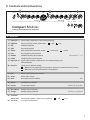
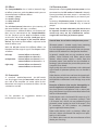
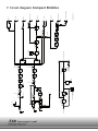
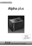
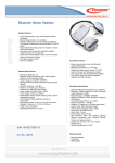
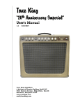
user manual Compact Mobile2 The L o 2012 ok ha : s cha nged ! Register your bile2: Compact Mo s.com www.aer-amp rvice > Customer Se 1 Compact Mobile2 user manual Contents 2 Page 1. Introduction 3 2. Safety Instructions 4 3. Controls and connections 3.1 Front side 3.2 Rear side 5 5 6 4. Starting up 4.1 Cabling and switching-on 4.2 Level adjustment 7 7 7 5. Functional characteristics 5.1 Equalization 5.2 Effects 5.3 Footswitch 5.4 Phantom powering 5.5 Battery operation and care 7 7 8 8 8 9 6. Technical specificatios 10 7. Circuit diagram 12 1. Einleitung Welcome to B! Thank you for purchasing the Compact Mobile2. The Compact Mobile2 is a professional, compact and powerful amplifier, specially designed for the amplification of acoustic instruments, but equally suitable for electric instruments and voice, furthermore you can add a playback-signal to your performance. The internal battery allows you to operate your Compact Mobile2 up to 4 hours without connecting the amp to the mains. All AER-systems are subtly dynamically controlled which ensures absolute reliability in full load operation despite strikingly small sizes and little weight. Read on and have fun using your Compact Mobile2! 3 2. Safety instructions The following guidelines shall help minimize the risk of injury through fire or electric shock. 1. Carefully read these safety notes before you use the device! 2. Keep these safety notes in a safe place. 3. Pay attention to all warnings, instructions and additional texts on the unit. 4. Do not install or use your device in close proximity to water or if you are wet yourself. 5. Use your device in a safe place where nobody can step on cables or trip over and damage them. 6. Always pull the mains plug before cleaning your device. Use only a dry cloth for cleaning. Avoid the use of detergents and do not let any liquids seep into the unit. 7. Never install your device close to units with strong electromagnetic fields such as large mains transformers, revolving machines, neon illumination etc. Do not lay signal cables parallel to power current cables. 8. There are no user-serviceable components inside the unit. To avoid the risk of an electric shock, the unit must not be opened. All maintenance, adjustment and repair works should be carried out by qualified staff only. Any unauthorized tampering will void the 2-year warranty. 9. In keeping with the EMV regulations screened cables with correctly fitted connectors must be used for all signal connections. 10. Always use an earthed power supply with the correct mains voltage. If you are in doubt about the power outlets ground, have it checked by a qualified technician. 11. Cable up your device only when it is powered off. 4 3. Controls and connections 3 input 1 3 gain high clip low 2 4 colour 5 bass 6 middle treble 7 8 input 10 9 14 gain line clip mic 4 bass treble 6 pan 8 select 11 12 level power 13 master 15 efx channel 1 channel 2 Compact Mobile2 low battery charge 16 17 aux level phantom power 48V 18 off on 19 battery-powered acoustic amplifier IB_CPM_120718 3.1 Front side 1) input (ch. 1) signal input, socket for 6,3 mm mono jackplug 2)high/low input sensitivity switch, attenuator 3)clip overload indicator 4)gain input level control 5)colour tone colour filter activation switch 6)bass bass frequency level control 7)middle middle frequency level control 8)treble treble frequency level control = off = on = not active = active channels 1 + 2 9) input (ch. 2) signal input, combo-socket for 6,3 mm mono jackplug and XLR-connectors 10) line/mic signal source selector switch: = line (only via jackplug) for instruments (pickup) and other line level sources = mic (only via XLR-connector) for microphones 11) pan effect signal distribution control 12) select effect select switch 13) level level control internal effect 14) power on/off status indicator 15) master master level control efx mains & master 16) low battery battery status indicator 17) charge battery charge indicator 18) phantom power 48V 48V phantom power switch for microphone 19) aux level aux-signal level control mains battery & control master = off = on 5 L R 1 2 line out send 4 tuner 6 8 L Compact Mobile2 battery-powered acoustic amplifier Compact Mobile2 aux in headphones line out return send headphones return 3 R aux in 5 7 footswitch tip tuner = int. efx DI-out ring = ext. efx on/off 1 = gnd 2 = pos 3 = neg footswitch DI-out tip = int. efx ring = ext. efx on/off 1 = gnd 2 = pos 3 = neg battery-powered acoustic amplifier CAU T I O N RISK OF ELECTRIC SHOCK DO NOT OPEN AT T E N T I O N RISQUE DE CHOC ELECTRIQUE NE PAS OUVRIR CAU T I O N power on RISK OF ELECTRIC SHOCK DO NOT OPEN AT T E N T I O N IF_CPM_120718 RISQUE DE CHOC ELECTRIQUE NE PAS OUVRIR 12V DC only DC 1= – / 2= + on/off 9 10 11 power on 12V DC only DC 1= – / 2= + on/off IF_CPM_120718 3.2 Rear side IF_CPM_120718 1) aux in: stereo input for additional signal sources, e.g. CD-player, Cinch/RCA-sockets (white = left channel, red = right channel) 6) tuner: The tuner output supplies a pre-master signal (-9 dbV) to connect an external tuner to the Compact Mobile2. 2) line out: The line out supplies a pre-amp signal taken after tone-control, effects and master for forwarding to other appliances. 7) footswitch: Connection socket for a doublefootswitch (on-/off-switch, tip = internal effect/ring = external effect on/off ). 3) headphones: This output enables you to connect stereo headphones and mutes the loudspeaker. 8) DI-out: Preamp-output with symmetrical signal, after tone-control, pre master, without effects. !!!Warning: Only use headphones with stereo jackplugs in this output socket!!! 9) 12V DC only: Connection socket for an optional 12V-cable to an external battery. 4) send: Send is an output to connect to an external effect device and in conjunction with return (input) forms a loop here designed as external effect loop. The effect can be switched on or off via footswitch. 5) return: Return as part of the effect loop operates as signal input from an external effect device (from output of the effect device). The effect can be switched on or off via footswitch. Return on its own can also be used as quasi auxiliary signal input (-10 dbV). 6 10) DC on/off: On/off-switch for the connection socket (9). 11) power on: Combined mains switch with mains socket and fuse holder. 4. Starting up 4.1 Cabling and switching on Before connecting to mains, please ensure that your local mains voltage is suitable for the voltage of the device (e.g. 120V in the USA, 230V in Europe). The relevant specs and safety symbols are printed on the rear side of the unit. Connect all cables according to your application and switch the amplifier on. The green power control LED indicates operational readiness. The clip-LED indicates an overload. A short flicker is of no danger to AER devices. During operation a short flicker can be accepted, to be on the safe side you should reduce the gain slightly to achieve an optimal and distortion-free performance. Finally set the desired overall volume level with the master level control. 5. Functional characteristics 5.1 Equalization Note: The active equalization of the CompactMobile2 effects the signal adjustment. If you spot an intensified flickering of the clip indicator, level the signal level with the gain control (s. 4.2 Level adjustment). 4.2 Level adjustment Note: Level adjustment By setting the level correctly we mean the signal level in one or several devices in a signal chain is neither too high nor too low. This applies equally to all circuits in a complete circuit design (EQs, preamps etc.) Consequently, care must be taken that no part of the circuit is overloaded or that distortion is unintentionally added to the signal. We have carefully designed the circuit to achieve this objective whilst also providing controls for „manual“ intervention. The triple-/dual-band equalizer of your CompactMobile2 provides you with an active and high quality sound interaction tool that supports the natural tone of instruments and voice whilst simultaneously offering you the possibility of a controlled accentuation. With all controls in mid position the filters are set to produce a very pleasing and natural sound impression that you can „colour up“ by using the colour filter with the effect of lowering the mids and lifting the trebles. The tone becomes more open and light and is especially suited for fingerpicking techniques. The equalization can support or soften the effect of the colour filter and allows a differentiated midsaccentuation. channel 1 Compact 603 channel 2 IF_Compact603_20120529 First ensure, that the master level control is zeroed (over to far left), so that when you are setting the sound level, the signal passes through the electronics only and does not reach the loudspeaker. By pressing the high-/low- (attn.) resp. line-/micswitches you can adapt the amplifier to your signal sources (guitar pickups, microphone etc). Turn the gain control clockwise until the red clip indicator flashes momentarily when playing with a strong attack. Thus you make sure that your signal source (e.g. instrument) provides the input-stage of the amplifier with the necessary input. Compact 603 A: with colour-filter (switch pressed) reduce treble to soften possible sharpness colour bass middle treble B: without colour-filter (switch not pressed) boost treble to brighten the sound colour bass middle treble 7 5.2 Effects 5.4 Phantom power The CompactMobile2 has a built-in (internal) digital effects processor, with the select-switch you can choose between 4 different effects: Microphones requiring 48V phantom power can be connected to the XLR-socket of channel 2 directly. Factory-provided phantom power is activated but, if required, may be deactivated by an internal jumper. 1 = reverb 1 (short) 2 = reverb 2 (long) 3 = delay (320 ms) 4 = chorus The efx-level-control determines the intensity of the internal effects (left stop = no effect). Furthermore an additional effects unit (external effect) may be connected to the CompactMobile2. For this purpose use the send and return sockets on the rear side of the amplifier (send goes to input, return to the output of the external effects device). The intensity of the effect is adjusted at the external effects unit. With the efx-pan control the different effects are blended with the original signal. The efx-pan works as follows: left stop: internal effect on channel 1 external effect on channel 2 mid position: internal effects on channel 1 + 2 external effects on channel 1 + 2 right stop: internal effects on channel 2 external effects on channel 1 5.3 Footswitch A standard double-footswitch (on-/off-switch) can be plugged into the footswitch-socket on the rear side of the amplifier via stereo cable. By this footswitch the internal and external effects can be switched on and off. P.S. For questions or suggestions contact us: [email protected] In contrary 9V phantom power, if required, can additionally be activated in channel 1 by an internal jumper. Please note: For both alterations the device must be opened, therefore only qualified service personnel may carry out the modifications concerning the de-/activating of phantom power. General Note: Use of 48V or 24V phantom power (Phantom power = remote supply, here: powering an audio device via the connected audio line) Turn on the phantom power only if the unit connected to an XLR socket that is designed to handle it! In general, suitable units are e.g. condenser microphones, active DI-boxes and other special audio devices, whose power supply is drawn from the phantom power. Such devices are also labelled accordingly; please heed the permissible power consumption (max.10mA). High-quality dynamic microphones with a balanced signal need no phantom power, but can handle it anyway. Other devices, which have not been designed explicitly for phantom power operation, can suffer from considerable malfunctions and damage may result as well. Examples of devices that may be damaged by incorrect application of phantom power include: Low-cost dynamic microphones with a mono jackplug (unbalanced signal) that were fitted afterwards with an XLR connector. Audio devices with a balanced XLR output (e.g. DIboxes, effects devices, instrument preamps with a DI output etc.) which are not protected against phantom power applied to their XLR output. (The DI connectors on AER products are protected against applied phantom power.) Other audio devices (such as preamps, effects pedals etc.) whose unbalanced line output was replaced by an XLR socket. If in doubt please consult the manufacturer of the device you are using. 8 5.5 Battery operation and care The battery in your CompactMobile2 is a high-end leakproof and maintenance-free lead-gel-battery. It‘s high capacity will be available for a long time if you follow some precautionary measures. 1. Charging To charge the battery, plug your AER CompactMobile2 to the mains and switch it on. If you do not want to use the amplifier during the charging process, turn gain- and master-control to minimum volume (as far left as possible). The charging of the batteries will be indicated by the yellow charge-LED. The battery is fully charged when the charge-LED is off. Charging time depends on various factors and can vary according to the battery’s charging state at the beginning of the process. A partly discharged battery will be charged completely after a few hours whereas the charging process of a completely discharged battery can last more than 24 hours. The average charging-time of a continually discharged battery will take about 8 to 14 hours. By constantly controlling the battery’s voltage, the intelligent charge control electronics prevents the battery from overcharge. 2. Operation A completely charged battery allows 2 to 4 hours of playing independent of mains supply, depending on volume and dynamics. Low volume will enable you to play up to 8 hours. The low-battery-LED indicates that the battery is almost empty. As soon as the minimal allowed battery voltage has been reached, the charge control electronics will automatically switch the AER CompactMobile2 off, in order to avoid deep-discharge. After the amplifier has been switched off by the charge control electronics it can only be operated when connected to the mains. A discharged battery should be charged as soon as possible. Storage in discharged condition may damage the battery. the battery irreparably by natural self-discharge. During normal use, the charge control electronics can protect the battery from deep-discharge, but it cannot prevent the electronical process of selfdischarge in the battery itself. Always store your AER CompactMobile2 with charged battery. A fully charged lead-gel-battery will still be 60% charged after one year of storage whilst a discharged battery might be damaged even after a few weeks. 4. Temperature Dependency Please note that the battery’s capacity (and thus playing time) depends on the surrounding temperature. Playing outside in winter will reduce playing time by 20 to 30% compared to playing in heated rooms or outside in summer. This is a normal reaction and not a sign of a defective battery. 5. Battery Life Expectancy The producer of the batteries used in the AER CompactMobile2 declares a life period of approximately 5 years at intended use. 6. Warranty Batteries are items that wear out through the ordinary course of use, thus they are excluded from statuary two-year liability. If a defect has not been caused by AER manufacture, warranty will expire after 6 months. 7. Battery Exchange The exchange of worn out batteries should be carried out by a specialist or by AER Service as both amplifier and new battery could be severely damaged through improper connecting or assembly. Improper connection may cause explosion or electric shock. 3. Storage and self-discharge If your AER CompactMobile2 is stored or not used over a long period, the battery should be fully charged in order to keep it‘s capacity. Being switched off for a long time with discharged battery may damage PB 9 Technical data 6. Technical specifications Compact Mobile2 – page 1 Inputs channel 1 channel 2 aux in return High impedance, unbalanced instrument or line input Mono jack socket, ¼“ (6.35 mm) Min. input voltage: 22 mV (–33 dBV) Max. input voltage: 5 V (+14 dBV) Input impedance: 2.2 M || 350 pF Equivalent input noise voltage (A-weighted): 1.5 μV (– 117 dBV) High/low (attenuator) switch: –10 dB Phantom power: Optional (see notes), 9 V DC / max. 100 mA, on ring of input jack, short circuit protected clip indicator Headroom: min. 6 dB Switchable line / microphone input Combo socket, XLR + jack ¼” (6.35 mm) line mode (via jack input only) High impedance, unbalanced instrument or line input Min. input voltage: 27 mV (–31 dBV) Max. input voltage: 7 V (+17 dBV) Input impedance: 2.2 M || 350 pF Equivalent input noise voltage (A-weighted): 2.4 μV (– 113 dBV) mic mode Microphone input, XLR (balanced), stereo jack (balanced), or mono jack (unbalanced) 1 / sleeve = ground, 2 / tip = positive (+), 3 / ring = negative (–) Min. input voltage: 3.3 mV (–50 dBV) with low-gain option: 5.8 mV (–45 dBV) Max. input voltage: 1 V (0 dBV) with low-gain option: 1.8 V (+5 dBV) (see notes) Input impedance (balanced): 1.2 k Input impedance (unbalanced): 2.7 k Voice filter: –10 dB at 270 Hz referred to 10 kHz Equivalent input noise voltage (A-weighted): 0.9 μV (–121 dBV) Phantom power: XLR only, 48 V, switchable, R = 6.8 k per terminal, max. 10 mA total, short-circuit protected clip indicator Headroom: min. 6 dB Auxiliary stereo input, e.g. for CD player Cinch (RCA) sockets, L / R Level adjustable by aux level Min. input voltage: 100 mV (–20 dBV) Max. input voltage: 3.5 V (+11 dBV) Input impedance: 22 k Input from external parallel effect loop, or supplementary input Mono jack, ¼” (6.35 mm) Min. input voltage: 320 mV (–10 dBV) Max. input voltage: 5 V (+14 dBV) Input impedance: 20 k (but 5 k while external effect is switched OFF by footswitch) Outputs line out Line output after master, with aux in and effects Mono jack, ¼” (6.35 mm) Output voltage: 700 mV (–3 dBV) Output impedance: 100 Min. load impedance: 2 k Residual noise (A-weighted): 4.5 μV (–107 dBV) www.aer-amps.com CompactMobile2 - 2012_07_GB 10 headphones Headphones output Stereo jack socket, ¼” (6.35 mm), L/R connected When plugged in, internal speaker is muted. Output power at rated conditions: 2 x 8 mW / 32 Max. output power: 2 x 100 mW / 1000 Output impedance: 470 (common for L/R) Min. load impedance: not limited Note: Suitable for stereo headphones with send Output for external parallel effect loop, before master, after tone controls Mono jack, ¼” (6.35 mm) Output voltage (efx pan fully clockwise): 900 mV (–1 dBV) Output impedance: 47 Min. load impedance: 2 k Tuner output, after tone controls, before effects and master Mono jack, ¼” (6.35 mm) Output voltage: 225 mV (–13 dBV) Output impedance: 47 Min. load impedance: 2 k Balanced, non-isolated XLR output, after tone controls, without aux in and effects 1 = ground, 2 = positive (+), 3 = negative (–) Output voltage (differential): 93 mV (–21 dBV) Output impedance: 47 , each terminal to ground Min. load impedance (differential): 1 k stereo jack only. Not functional with mono jacks. tuner DI-out Footswitch connector footswitch Connector for a dual footwitch Stereo jack, ¼” (6.35 mm) Tip = internal effect on/off Ring = external effect on/off Sleeve = common (ground) Function: Switch ON = effect OFF Tone controls Channel 1 Channel 2 colour bass middle treble bass treble –3 dB at 700 Hz +10 dB at 8 kHz 8 dB at 100 Hz (shelf type) 6 dB at 800 Hz 8 dB at 10 kHz (shelf type) 8 dB at 100 Hz (shelf type) 11 dB at 10 kHz (shelf type) Effects Internal effects External effects efx pan Digital effect processor 1 Reverb (short predelay) 2 Reverb (long predelay) 3 Delay (320ms, repetitive) Chorus 4 Parallel effect loop, see send and return Blends both internal and external effects between channels 1 and 2, with reverse direction of rotation for the external effects. 6. Technical specifications Compact Mobile2 – page 2 Power Power amp Mains power Mains fuse Internal battery NOTES 60 W / 4 (1% THD) Monolithic IC with DMOS output Dynamic range (A-weighted): 94 dB Mains voltage (depending on model): 100, 120, 230, or 240 V AC, 50–60 Hz Power consumption: max. 240 W Power consumption (only charging): 45 W Size: 5 x 20 mm Rating: For 230 and 240 V models: T 1 A L / 250 V For 100 and 120 V models: T 2 A L / 250 V Type and 2 rechargeable sealed lead-acid rating batteries, each 6 V / 12 Ah Operating ca. 3 – 4 h depending on time volume 100% full charge: ca. 16 h Recharge 90% full charge: ca. 12 h time Without output load. Important Charge batteries soon when empty. Never store with empty batteries! Recharge once a year when not in use. 12 V DC connector The power switch must be ON in order to charge the battery. Input for operating the Compact mobile from an external 12 V battery Max. current consumption: 10 A 1 = minus (–) 2 = plus (+) Note: This input can not be used to charge the external battery from the Compact mobile or to charge the internal battery from an external power source. General Distortion Analog signal processing Limiter threshold Speaker system Cabinet Finish THD + N < 0.1% at 6 W / 4 Subsonic filter, adaptive peak limiter 50 W / 4 8” (200 mm) dual cone full-range speaker, bass reflex enclosure 12 mm (0.47“) birch plywood Waterbased acrylic, black spatter finish Rated conditions: Nominal input voltage: 50 mV at input of channel 1. Test signal: 1 kHz sine unless stated otherwise. Signal voltages stated as RMS values. 0 dBV corresponds to 1 V RMS. Gain of channel under test fully clockwise. Tone controls in center position, colour off. Master adjusted such that the rated output power is obtained (requires that the limiter is disabled). To avoid having to disable the limiter, master can be adjusted such the rated output voltage at line out is obtained instead. Output voltages refer to rated conditions as stated above. Min. input voltage: Input voltage required for rated output power (limiter disabled) with gain and master fully clockwise Max. input voltage: Input voltage that does not cause more than 1% THD+N, suitable control settings provided THD + N: Total harmonic distortion + noise, with input and output levels 10 dB below rated conditions. Equivalent input noise voltage: Noise voltage at speaker output divided by gain of amplifier. gain of input under test fully clockwise, master fully clockwise, gain of unused inputs minimal. Input shorted, B = 22 Hz … 22 kHz Residual noise: Noise of an output when its level control is set to minimum. Dynamic range (power amp): Ratio of rated output voltage to residual noise voltage (master fully anticlockwise). Options: The following options are available by internal jumper settings. 1) Gain of microphone input can be reduced, resulting in more headroom. 2) 9 V phantom power for channel 1 can be activated. Caution: Install only if required. Phantom power may damage external equipment. Read the operating instructions. Specifications and appearance subject to change without notice. TD20121011 Dimensions and weight Dimensions Weight 320 mm (12.8“) high 326 mm (12.9“) wide 282 mm (11.1“) deep 13 kg (28.7 lbs) www.aer-amps.com CompactMobile2 - 2012_07_GB 11 R T 1 MAINS INPUT CH2 R T 2 CH1 3 CompactMobile2 - 2012_07_GB 6k8 www.aer-amps.com 6k8 POWER CHARGER +48V RECHARGEABLE BATTERY (INTEGRATED) CHARGE AC POWER SUPPLY 48V OFF/ON PREAMP VOICE MIC CLIP DETECTION BASS TREBLE TREBLE CLIP DETECTION CLIP DETECTION 12V DC BATTERY EXTERNAL DIGITAL EFFECTS EFX / SELECT Power supply to amplifier 12V DC ON/OFF DEEP DISCHARGE PROTECTION MIDDLE VOLTAGE MONITOR GAIN BASS LOW BATTERY COLOUR COLOUR MIC MIC GAIN H/L GAIN LINE PREAMP HIGH / LOW PREAMP CLIP DETECTION LINE +9V CW EFX / PAN CW 9V Phantom Power SUBSONIC EFX / LEVEL LIMITER POWER AMP MASTER AUX LEVEL 470R T T R R 3 R L DUAL CONE SPEAKER HEADPHONES LINE OUT AUX IN RETURN FOOTSWITCH SEND TUNER DI-out B090408B_20121017 1 2 7. Circuit diagram Compact Mobile2