1
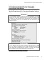
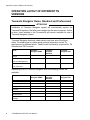
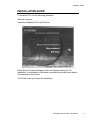
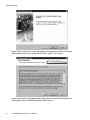
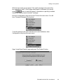
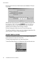
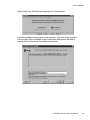
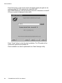
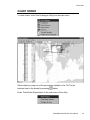
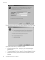
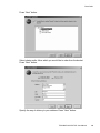
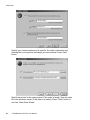
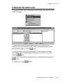
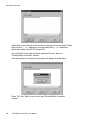
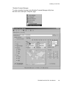
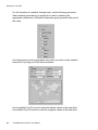
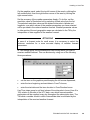
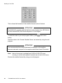
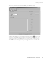
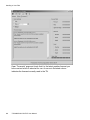
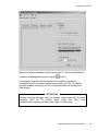
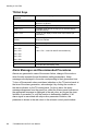
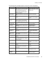
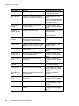
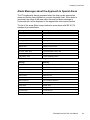
TSUNAMIS NAVIGATOR USER MANUAL Transas Ltd. May, 2004 © Transas Ltd. 2004 All rights reserved. The information contained herein is proprietary to Transas Ltd. and shall not be duplicated in whole or in part. The technical details contained in this manual are the best that are available at the date of issue but are subject to change without notice. Transas Ltd. pursues the policy of continuous development. This may lead to the product described in this manual being different from the product delivered after its publication. Microsoft and Widows are registered trademarks of Microsoft Corporation. The names of actual companies and products mentioned herein may be the trademarks of their respective owners. This document contains: System Requirements for Tsunamis Navigator Software.........................3 System Requirements for Tsunamis Navigator System...................................3 Operation Layout of Different TN Versions ...................................................4 Tsunamis Navigator Demo, Standard and Professional...................................4 Installation Guide ..........................................................................................7 Setting of user permits ...............................................................................12 Chart Installation .........................................................................................14 Chart Order ..................................................................................................17 Connection of External Sensors................................................................21 Handling or User Files ................................................................................25 Weather Forecast Manager ........................................................................27 TN Hot Keys.......................................................................................................34 Alarm Messages and Recommended Procedures .........................................34 Alarm Messages about the Approach to Special Areas .................................37 Annex A. NMEA Telegrams ........................................................................39 Positioning System ............................................................................................39 Time Sensor.......................................................................................................39 Echo Sounder ....................................................................................................39 Wind Sensor.......................................................................................................40 Water Temperature ...........................................................................................40 Gyro/Magnetic Compass Sensor .....................................................................40 Yeoman Digitizer................................................................................................40 WP out Port ........................................................................................................41 Output/Autopilot .................................................................................................41 Output ARPA/Radar ..........................................................................................42 TSUNAMIS NAVIGATOR. User Manual. 1 System Requirements for Tsunamis Navigator Software SYSTEM REQUIREMENTS FOR TSUNAMIS NAVIGATOR SOFTWARE System Requirements for Tsunamis Navigator System ATTENTION! For the warranted operation of the ECS Tsunamis Navigator, you should carefully study the system requirements for the computer which the TN will be installed in. If the computer system requirements differ essentially from the recommended ones, the TN installation will be interrupted by the installation program. ATTENTION! The TN operation does not permit the setting of any other fonts but small fonts. If you have any problems with the display of information on the TN screen, check the font setting on your computer. To do this, open Settings page in Windows Control Panel/Display and set the small fonts. PS: Requiring to insert OS WinXP in the picture. TSUNAMIS NAVIGATOR. User Manual. 3 Operation Layout of Different TN Versions OPERATION LAYOUT OF DIFFERENT TN VERSIONS Tsunamis Navigator Demo, Standard and Professional ATTENTION! Installation of Tsunamis Navigator system will automatically replace the Tsunamis'99 system if the latter was installed on the same computer. As this is done, chart installed in the Tsunamis'99 will remain available for use in Tsunamis Navigator system. Tsunamis Navigator electronic chart system may have one of the three levels. Provided below is a table which contains information on the TN requirements for different levels. Tide&Current functionality is optional for TN Standard and TN Pro levels. Level: Tsunamis Navigator DEMO Tsunamis Navigator Standard Tsunamis Navigator PRO Dongle - + + License - - + - Optional Optional Tsunamis Navigator Pro License Tide & Currents Depending on ECS Tsunamis Navigator level, the following utilities are available: 4 Utility: Tsunamis Navigator DEMO Tsunamis Navigator Standard Tsunamis Navigator PRO Tsunamis Navigator + + + Chart Catalogue + + + Configuration + + + Playback - - + Navtex Receiver - - + Navtex Viewer - - + Weather Forecast Manager + + + TSUNAMIS NAVIGATOR. User Manual. Operation Layout of Different TN Versions Depending on the set level, the TN can use the following panels: Panels: Tsunamis Navigator DEMO Tsunamis Navigator Standard Tsunamis Navigator PRO Main + + + Dual - + + Info + + + Monitoring - + + Ship Position - + + Route Monitoring - + + Navigational Alarms - - + Config + + + General + + + Weather Parameters Settings + + + Time Zone + + + Tasks - + + SAR - - + Tides - Optional Optional 3D - - + Names - + + LogBook - - + Add Info - + + Route + + + Calculations _ _ + Extra + + + Chart + + + For the TN's different levels, the use of the following navigation sensors is possible: Sensors: Tsunamis Navigator DEMO Tsunamis Navigator Standard Tsunamis Navigator PRO Positioning System (PS) NO YES YES Time (from PS) NO YES YES Gyro/Magnetic Compass NO NO YES Log NO NO YES Wind Sensor NO YES YES Echo Sounder NO YES YES Temperature sensor NO NO YES TSUNAMIS NAVIGATOR. User Manual. 5 Operation Layout of Different TN Versions Sensors: Tsunamis Navigator DEMO Tsunamis Navigator Standard Tsunamis Navigator PRO ARPA NO NO YES Yeoman digitiser NO NO YES Autopilot NO NO YES The following functionality is implemented in the Tsunamis Navigator Pro level only: 6 • passing of a route from the TN to an external device (GPS); • re-calculations of directions from true to magnetic and the other way round; • creating and editing of route schedules; • creating and editing of SAR (Search And Rescue) routes; • display of information on the seabed topography in the threedimensional form (3D); • operation with external NAVTEX receiver; • setting of safety parameters (Navigational Alarms) which, when exceeded, generate an alarm; • playback of archive data on the Chart Panel (Play Back); • use of external navigation aids (ARPA, autopilot, compass, log, digitiser, etc.); • dead reckoning mode. TSUNAMIS NAVIGATOR. User Manual. Installation Guide INSTALLATION GUIDE To install the TN, use the following procedure: Start the computer. Insert the installation CD in the CD drive. Select Setup Tsunamis Navigator menu item (before starting the TN installation, it is advisable to familiarise oneself with information provided by View readme.txt menu item). The TN will invite you to start the installation. TSUNAMIS NAVIGATOR. User Manual. 7 Installation Guide Press “Next” button: the screen will display and agreement which you should read carefully and, if you agree with its terms, press “Yes” button. In the window which will appear specify the place on the hard disk where the TN program will be installed and press “Next” button. 8 TSUNAMIS NAVIGATOR. User Manual. Installation Guide In the window which will appear, specify the place on the hard disk where the directory containing the chart folio to be used will be installed, press “Next” button. Familiarise yourself with the system requirements for the computer which should be met for the TN program installation. TSUNAMIS NAVIGATOR. User Manual. 9 Installation Guide Press “Next” button and check that you computer actually meets the system requirements imposed on the computer for the program installation. Press “Next” button. The program will perform the TN installation whereafter it will be necessary to restart the computer. 10 TSUNAMIS NAVIGATOR. User Manual. Installation Guide After the computer restart, the wizard program for the setting of parameters required for the TN operation will be automatically run. Press “Next” button to set the specified parameters or “Exit” to exit from the wizard. These parameters can be set at any time in Configuration utility whose operation is described further in the Manual. After the end of the wizard program operation, the TN installation on your computer is completed. The TN and utilities are run from the main menu. You will have Tsunamis Navigator Demo level set. TSUNAMIS NAVIGATOR. User Manual. 11 Setting of user permits SETTING OF USER PERMITS To set Tsunamis Navigator Standard level shut down the computer. Insert the appropriate security key in the LPT or USB computer port. Start the computer and run the TN from the main menu. Tsunamis Navigator Standard level will be installed on your computer. To set Tsunamis Navigator Pro level, enter Configuration utility from the main menu. Open Install User Permits page and press For Product button: Enter the Tsunamis Navigator Pro permit in 'Tsunamis Navigator Pro' level box: 12 TSUNAMIS NAVIGATOR. User Manual. Setting of user permits With the input of the correct permit, "Not valid" message to the right of the box changes to "Valid". At this stage Install button is activated; you should press button to install the permit. Information on permit(s) installed window will display "permit included" message. Exit from Configuration utility and run the TN from the main menu. You will have Tsunamis Navigator Pro level set. To set the permit for the use of the tide and current database, enter Configuration utility from the main menu. Open “Install User Permits” page and press “For Product” button: TSUNAMIS NAVIGATOR. User Manual. 13 Chart Installation Enter the permit for the use of the tide and current database in Tide and Current box: With the input of the correct permit, "Not valid" message to the right of the button is activated; you box changes to "Valid". At this stage should press this button to install the permit. Information on permit(s) installed window will display "permit included" message. Exit from Configuration utility and run the TN from the main menu. The selective installation of charts and chart catalogues depending on the need to use them, is made in Chart Catalogue utility. CHART INSTALLATION To be able to use electronic charts in the TN, you will have to install chart permits and then the charts from the WF CD. To install all the licensed charts, use Chart Setup Wizard. To start Chart Setup Wizard, run Configuration utility from the main menu. 14 TSUNAMIS NAVIGATOR. User Manual. Chart Installation Open Install User Permits page and press For charts button: Enter the available chart permits in the input box. If permits.txt file supplied with the chart folio is available, press Load button and specify the path to permits.txt file. Permits will be loaded automatically. TSUNAMIS NAVIGATOR. User Manual. 15 Chart Installation Press Next button; in the window which will appear specify the path for the scanning of the WF CD containing the chart folio (CD Drive:\CHARTS\setup.id). After the scanning of the CD, information on the WF CD issue number is displayed in the centre: Press “Finish” button to start the chart installation. The TN installs all the charts which permits are available for. Chart installation can also be performed from Chart Catalogue utility. 16 TSUNAMIS NAVIGATOR. User Manual. Chart Order CHART ORDER To order charts, enter Chart Catalogue utility from the main menu. Select charts by using one of the procedures available in the TN. Put the selected chart in the bucket by pressing button. Press Tools/Order Wizard button in the main menu of the utility. TSUNAMIS NAVIGATOR. User Manual. 17 Chart Order Enter your name and the name of the company (agency). Press “Next” button. Specify the permits which you would like to order: 18 • "Tsunamis Navigator" level – security key for Tsunamis Navigator Standard level; • "Tsunamis Navigator Pro" level – permit for Tsunamis Navigator Pro level; • Tide&Current module –permit for the access to the tide and current database. TSUNAMIS NAVIGATOR. User Manual. Chart Order Press “Next” button. Select charts and/or folios which you would like to order from the bucket. Press “Next” button. Specify the way of delivery to your address. Press “Next” button. TSUNAMIS NAVIGATOR. User Manual. 19 Chart Order Specify your contact numbers to be used for the order confirmation and advising the cost of permits and charts you have ordered. Press “Next” button. Specify the printer for the order printout (if the order is faxed). Save the order file to an electronic carrier (if the order is e-mailed). Press “Finish” button to exit from Chart Order Wizard. 20 TSUNAMIS NAVIGATOR. User Manual. Connection of External Sensors CONNECTION OF EXTERNAL SENSORS Connect outputs of the external devices to the computer serial ports (COM 1, COM 2, etc.) with RS-232C cable. Start the computer, run Configuration utility from the main menu and open Sensors page. For the automatic connection of external sensors to the computer and automatic adjustment of serial ports, press “Auto” button. Check that the data supplied by the external sensors arrives for processing in the TN. Table cells containing this data should have a green background. If there is no green background in a cell containing the supplied data, make a double mouse click in the cell field. TSUNAMIS NAVIGATOR. User Manual. 21 Connection of External Sensors If the external sensors (Input group) have not been detected when connected automatically, as well as when it is necessary to transmit data from the TN to different external devices (Output group) perform manual connection of external devices to the computer serial ports. To do this, press Manual button. 22 TSUNAMIS NAVIGATOR. User Manual. Connection of External Sensors For the connection of external navigation sensors, set the serial port numbers next to each of the external sensors in use in the corresponding cells of Ports column in Input Sensors area. In Alarm Timer column set the alarm generation time in the absence of a correct signal from the external output device. Press “Set” button. To connect and external device (GPS) to the computer serial port used for the route transmission from the TN onto this device, set the port number in WP out box in Port area. Set the format of transmitted messages by checking WPL and/or RTE checkboxes. For the connection of the autopilot set the serial port number in Output Port area. Set the format of transmitted messages. For the connection of Yeoman digitiser, set the port number in Yeoman digitizer area. TSUNAMIS NAVIGATOR. User Manual. 23 Connection of External Sensors To disconnect any of the sensors, set the communication port number to zero in the required sensor box of Input Sensors area and press Set button. Close Manual Config window by pressing “Close” button. Assign external navigation sensors to the computer ports by double clicking the mouse on the required table cell, or by pressing Arrange button. After the assigning of the necessary sensors, data from the connected serial ports will be supplied to the TN. For the manual setup of the computer communication ports, press Ports button. Set the data exchange parameters corresponding to your external device in the table cells. Confirm the settings made for the port by double clicking the left mouse button on the port name. The name of the set serial port is shown against the light blue background. For the automatic setup of the computer serial ports, press left of the port name. The button will acquire the form of port by double clicking the left mouse button on its name. 24 TSUNAMIS NAVIGATOR. User Manual. button to the . Set the serial Handling or User Files HANDLING OR USER FILES To handle user files, enter Configuration utility from the main menu and open “Data Tool” page. To copy TN files onto an external carrier, select a file in the left hand window. In the central window, select a folder on the external carrier which the file will be copied to. Press button. To copy files from an external carrier to the TN, select the file in the right hand window. Select the appropriate TM folder. Copy the file to the TN by button. pressing To delete files, select the file in the left hand or right hand window and press button. To convert files, press button. TSUNAMIS NAVIGATOR. User Manual. 25 Handling or User Files Select files on an external carrier, which are required to be converted. These are route file (*.rte extension) and user chart files (*.cra extension) which were used in the ECS Tsunamis'99. Convert the file to the new format by pressing “Convert” button in “Route/AddInfo Converter” window. If the converting is successful, the program will display a confirmation. Press “OK” and “Next” in turn to exit from “Route/AddInfo Converter” window. 26 TSUNAMIS NAVIGATOR. User Manual. Handling or User Files ‘Weather Forecast Manager To order a weather forecast, enter Weather Forecast Manager utility from the main menu and open “Request” page. TSUNAMIS NAVIGATOR. User Manual. 27 Handling or User Files For the formation of a weather forecast order, use the following procedure. Select weather parameters you would like to order by checking the appropriate checkboxes of Weather Parameters group (pressure and wind in this case). Use Area group to set the geographic area which you wish to order weather forecast for, by using one of the two procedures: Use Longitude From/To boxes to enter the latitude values of the area limits. Use Latitude From/To boxes to enter the longitude values of the area limits. 28 TSUNAMIS NAVIGATOR. User Manual. Handling or User Files On the graphics panel, select the top left corner of the area by clicking the left mouse button, then the right bottom corner of the area by clicking the right mouse button. Set the accuracy of the weather parameters display. To do this, set the resolution value in Resolution box by selecting a fixed value from the list. The selected resolution values set the distance intervals in latitude and longitude, over which values of the weather parameters you have selected will be provided in the ordered weather forecast. Weather parameter values in other points of the set geographic areas are calculated in the TN by the interpolation of data supplied in the weather forecast. ATTENTION! In case of a forecast order for small areas, it is necessary to select the minimum resolution for a more accurate display of weather forecast parameters. In Time Range group, set the subscription term during which you wish to receiver weather forecast. This can be dome by using one of the following three procedures: • set the term on the graphics panel keeping the left mouse depressed; • enter the term beginning and end dates in From/To boxes; • enter the start date and the term duration in From/Duration boxes. Use Time steps group to set fixed values of time intervals in hours (from 0 to 120) relative to the start of the UTC date, over which forecast weather parameters will be supplied every day throughout the subscription term. The TN builds a weather model in which intermediate data is calculated by the interpolation of the received weather forecast. TSUNAMIS NAVIGATOR. User Manual. 29 Handling or User Files This is where the formation of the weather forecast order is finished. ATTENTION! The WFM utility operates with the following mail programs only: MS Outlook 98, MS Outlook 2000, MS Outlook Express v.5.5 and higher. To send the order to your mail program Outbox, press button. main menu Send the order to the Transas Weather Server via Internet by using the mail program. ATTENTION! The recommended time interval between the despatch of the weather forecast order and a request for its reception should be at least 30 minutes. Note: data on the server is updated from 04.30 to 06.30 UTC every morning, so at this time weather forecasts are not sent to the users. Receive the weather forecast by using your mail program. 30 TSUNAMIS NAVIGATOR. User Manual. Handling or User Files To receive a weather forecast in the WFM, open “Delivery” page. button in the In Check Mail Mode group, check Manual checkbox. Press main menu panel. The received weather forecast will be passed you're your mail program Inbox to the WFM. After the reception of the weather forecast, the WFM will automatically start its processing for the further use in the TN. TSUNAMIS NAVIGATOR. User Manual. 31 Handling or User Files Open “Forecasts” page and check that it is the latest weather forecast you have received which is selected for use. An arrow in Selected column indicates the forecast currently used in the TN. 32 TSUNAMIS NAVIGATOR. User Manual. Handling or User Files Select any received weather forecast as required. To do this, check Manual button. checkbox in Management group and press At this stage, reception and processing of the weather forecast are completed, and the received forecast can be used in the TN. To view the received weather forecast in the TN, use Animate button of Environment Data display. ATTENTION! Weather Forecast Manager utility can operate concurrently with Tsunamis Navigator. With the TN running, press <Ctrl> and <Esc> keys simultaneously to display the Start menu, then run WFM utility. TSUNAMIS NAVIGATOR. User Manual. 33 Handling or User Files TN Hot Keys Standard computer keyboard Brief statement of purpose <F4> To make an instantaneous position record in the ship electronic log (Event) <F8> To turn on Navigation Mode (Ahead) <Shift>+<F7> To display chart objects belonging to the standard display (Standard display) <Shift>+<F8> To turn on the display of all the chart object classes (All information) <Ctrl>+<PrtScrn> To make a graphic copy of the TN screen <PrtScr> Only for the Win98 <Ctrl>+<A> To acknowledge an alarm <Alt>+<F1> <Alt>+<F2> To switch screen palette successively to suit the time of the day: <Alt>+<F3> <Alt>+<F6> – under OS WinNT and Win2000 only <Alt>+<F4> <Alt>+<F5> <Alt>+<F6> <+> To increase the chart display scale <-> To reduce the chart display scale Alarm Messages and Recommended Procedures Alarms are generated in case of the sensor failure, change of the mode or when the ship exceeds the set limitations (safety parameters). Alarm messages are displayed in the order corresponding to their generation time. To turn off the acoustic alarm and alarm indication on the TN control panel at the time of the alarm generation, acknowledge it by clicking the mouse on the alarm indicator on the TN control panel. As this is done, the alarm message disappears from the panel line, whilst the Alarms panel indicator at the appropriate message is displayed in the red colour as long as the given limitation is exceeded, or until the function is deliberately disabled. If an alarm signal is associated with ship motion parameter limitation, this parameter is shown in the red colour in the relevant control panel window. 34 TSUNAMIS NAVIGATOR. User Manual. Handling or User Files The following alarm messages appear in the process of the TN operation: Alarm message Meaning Recommended procedure Ag. monitoring off with a change of a chart set under the ship position, there is no vector chart on a scale larger than that set in Check Scale Less function, which means the loss of control over the safety of navigation Set the scale value in Check Scale Less function to suit the available folio Anchor watch The ship is beyond the set anchorage area Check the ship position ARPA: no input The TN receives no data from the ARPA Check the operation and connection of the navigation sensor Chart datum unknown Coordinate system of the chart under the ship symbol is unknown (datum of the original paper chart is not known) and coordinate offsets have zero value Load another chart Check Pos-HDG-LOG At the TN start, DR positioning mode is set Check the ship position and motion parameters CPA/TCPA СРА and ТСРА are smaller than the set values Be careful about the dangerous target Diff. mode lost Loss of differential positioning mode for a period of time larger than the set value Check the ship position Gyrocompass: no input The TN receives no data from the compass Check the operation and connection of the navigation sensor Invalid heading data The TN receives incorrect data from the compass Check the compass operation Invalid log data The TN receives incorrect data from the log Check the log operation Last WP passed The ship has passed the last WP of the passage loaded in the ‘Voyage Monitoring Mode” Unload the passed route LOG: no input The TN receives no data from the log Check the operation and connection of the navigation sensor Nav. danger The ship is approaching the isolated danger Take note of the isolated danger Off chart The ship has sailed beyond the chart boundary with the chart autoload mode OFF Load a chart under the ship position Off course Deviation from the plotted route Check that the course set on the autopilot is correct Out of the schedule The ship is out of the route schedule Check the ship position and motion parameters TSUNAMIS NAVIGATOR. User Manual. 35 Handling or User Files Alarm message Meaning Recommended procedure Out of XTE Cross track error value exceeded Check that the course set on the autopilot is correct Prim. not WGS 84 Reception of coordinates which do not comply with WGS-84 coordinates Set WGS-84 datum in the sensor. Determine the ship position by some other method, switch to DR mode if required 36 Primary sensor: no input The TN receives no data from the positioning system Check the operation and connection of the navigation sensor PRIMARY Unreliable. position Unreliable ship positioning Establish the cause of the poor quality positioning Safety contour The ship is crossing a safety contour Check the ship position and motion parameters Safety contour changed With a change of the chart set under the ship position, the previously selected safety contour becomes unavailable Set a new safety contour value Sounder Depth Reception of the current depth of less than the set value from the sounder Be careful about the echo sounder readings Sounder: no input The TN receives no data from the echo sounder Check the operation and connection of the navigation sensor Temperature sensor: no input The TN receives no data from the water temperature sensor Check the operation and connection of the navigation sensor Time sensor: no input The TN receives no data from the time sensor Check the operation and connection of the navigation sensor Time zone changed Change of the ship time Check that the ship time has been changes correctly Timer went off Time set on the timer has expired Acknowledge the alarm message by pressing on ALARM function Unreliable wind data The TN receives incorrect data from the wind sensor Check the wind sensor operation Wind sensor: no input The TN receives no data from the wind sensor Check the operation and connection of the navigation sensor WP approach The ship has approached a WP Acknowledge the alarm message by pressing on ALARM function Yeoman failure The TN receives no data from the digitiser Check the operation and connection of the navigation sensor TSUNAMIS NAVIGATOR. User Manual. Handling or User Files Alarm Messages about the Approach to Special Areas The TN implements alarms generated when the ship symbol approaches areas and limiting lines digitised on a vector electronic chart. As an alarm is generated, the name of the area which the received alarm message is concerned with, will be displayed in the appropriate control panel window. The list of the areas (Basic areas) tracked in accordance with IEC-61174 standard is provided below: Message Meaning Anchor. Prohibited Anchorage Prohibited Anchorage area Anchorage Area Cable area Cable Area Fishing prohibited Fishing Prohibited Inshore traffic zone Inshore Traffic Zone Military area Military Practice Area Pipeline area Pipeline Area Recomm. traffic lane Recommended Traffic Lane Restricted area Restricted Area Traff. separ. zone Traffic Separation Zone Additional areas which alarms are generated for: Message Meaning Danger line Danger Line Exl. econ. Zone Limit of Exclusive Economic Zone Explosive dumping Explosives Dumping Ground Fishery zone Fishery Zone Harbour limit Harbour Limit Int.mar.boundary International Maritime Boundary Nature Reserve Limit of Nature Reserve Prohibited area Prohibited Area Swept area Swept Area Territor. sea base Straight Territorial Sea Base Line Territorial sea Territorial Sea Unsurveyed area Unsurveyed Area TSUNAMIS NAVIGATOR. User Manual. 37 Annex A. NMEA Telegrams ANNEX A. NMEA TELEGRAMS The TN navigation system processes and transmits the following NMEA – 0183 and IEC 61162-1 standard telegrams. The following telegrams are received from the navigation sensors. Positioning System • GGA – time, ship coordinates, HDOP, number of satellites used for positioning, operating mode of the satellite navigation system sensor, age of differential corrections, differential station identifier; • RMC – date, time, ship coordinates, COG, SOG, operating mode of the satellite navigation system sensor; • GLL – time, ship coordinates; • VTG – COG, SOG; • DTM – information on the datum set in the PS; • GSV – numbers, azimuths, altitude, SNR values for all the navigation system satellites within the visibility range. Time Sensor • ZDA – date, time, time zone; • ZLZ – time; • ZZU – time. Echo Sounder • DBT – depth under the keel; • DPT – depth under the keel; • DBK – depth under the keel; • DBS – depth under the keel. TSUNAMIS NAVIGATOR. User Manual. 39 Annex A. NMEA Telegrams Wind Sensor • MWV – direction and speed of the relative or true wind; • VWR – relative wind direction and speed; • VWT – true wind direction and speed. Water Temperature • MTW – sea water temperature. • LOG sensor: • VHW – log speed through the water; • VBW – log speed over the ground; • OSD – log speed through the water; Gyro/Magnetic Compass Sensor • HDM – magnetic course; • HDT – true course; • VHW – true or magnetic course; • OSD – true course. ARPA: • TTM – information on ARPA tracked targets; • OSD – relaying of course and speed from the ARPA. Yeoman Digitizer 40 • WPL – reception of latitude and longitude coordinates from the digitiser; • GLL – reception of latitude and longitude coordinates by the digitiser from the TN; • Telegrams for the transmission of information onto the external navigation sensors. TSUNAMIS NAVIGATOR. User Manual. Annex A. NMEA Telegrams WP out Port • WPL – WP geographic coordinates and identifier (information on all the WP's of the selected route is transmitted by using Upload Route functionality); • RTE – identifier of all the WP's (information on all the WP's of the selected route is transmitted by using Upload Route functionality). Output/Autopilot • APA – XTE value and the direction to reduce it, route leg direction value from the previous WP to the next WP; identifier of the next WP; • APB – XTE value and the direction to reduce it, route leg direction value from the previous WP to the next WP; identifier of the next WP, BTW value; • BOD – route leg direction value from the previous WP to the next WP; identifiers of the previous and next WP; • BWC -geographic coordinates and identifier of the next WP, BTW and DTW values, time; • XTE – XTE value and the direction to reduce it; • XTD – XTE value and the direction to reduce it; • PRAPA XTE value and the direction to reduce it, route leg direction value from the previous WP to the next WP; identifier of the next WP; • PASTE – XTE value and the direction to reduce it; • WPL – geographic coordinates and WP identifiers (information on the previous WP and 13 following WP's is transmitted); • RTE – WP identifiers (information on the previous WP and 13 following WP's is transmitted); • R00 – WP identifiers (information on the previous WP and 13 following WP's is transmitted); • VHW – ship compass course (magnetic and true), log speed through the water. TSUNAMIS NAVIGATOR. User Manual. 41 Annex A. NMEA Telegrams Output ARPA/Radar • GLL – ship time and coordinates; • VHW – ship compass course (magnetic and true), log speed through the water. • ZDA – ship date and time, time zone number set in the TN; • VTG – ship course (COG) and speed (SOG) over the ground; • VDR – drift speed and direction values; • WPL – geographic coordinates and identifiers of WP's (information on the previous WP and 13 following WP's is transmitted); • R00 – WP identifiers (information on the previous WP and 13 following WP's is transmitted); • RTE – WP identifiers (information on the previous WP and 13 following WP's is transmitted). IEC 61162-1, 1995 standard telegrams: APB, BWC, GLL (to Output only),VTG (to Output only), XTE. IEC 61162-1, 2000 standard telegrams: BOD, DBT, DPT, DTM, GGA, GLL, GSV, HDT, MTW, MWV, OSD, RMC, RTE, TTM, VBW, VDR, VHW, VTG, WPL, ZDA. NMEA 0183 v.2.1 (1995) standard telegrams: APA, DBK, DBS, HDM, R00, VWR, VWT, ZLZ, ZZU. Messages in the Anschuts autopilot own standard: PRAPA, PASTE. Messages of an unknown standard: XTD. ATTENTION! It should be noted that with the TN using magnetic directions, it is true values of bearing and route leg direction which are transmitted in messages to the autopilot. Passed in the VHW telegram is the ownship course value (HDG) both, in the magnetic and true directions, the magnetic variation used in the TN taken into account. 42 TSUNAMIS NAVIGATOR. User Manual.