1
Persistor® BigIDEA User's Manual
Copyright
© 1999, Persistor Instruments Inc. All Rights Reserved.
Revision 1.0 - May 1999
PRELIMINARY
Introduction
The Persistor BigIDEA is a 2"x3" IDE adapter that sandwiches between a Persistor CF1 miniature
single board computer and CF1 RecipeCards, other CF1 SandwichCard adapters, or your custom
CF1 electronics. The BigIDEA allows the CF1 to control 2.5" hard drives (2GB to 14GB), 1.8"
Type III PCMCIA hard drives (0.5GB and 1GB), or single/dual stack PCMCIA TrueIDE flash
cards (Type II, to 440MB).
The BigIDEA's power-switched electronics keeps the current drain below 15uA while you collect
and buffer data into RAM or the CF1's CompactFlash cards. When these fill up, you spin up the
power hungry drive, spool off the buffered data, then quickly shut it back off.
Each BigIDEA adds about 0.48" of height to a CF1 systems (you can stack several) and all
BigIDEAs in the system share the same SandwichCard chip select and memory space which leaves
your system with up to 31 additional SandwichCard chip selects for other expansion options.
Drives and Cards connected to the BigIDEA get to use the CF1's PicoDOS file system so they're
directly compatible with DOS/Windows9x PCs. The flash cards and PCMCIA hard disk plug into
standard PC Card slots and automatically mount as logical drives (E:, F:, etc.) for extremely fast
and easy data recovery.
The included BigIDEA driver software lets you access the file system through standard C function
calls (fopen, fread, fprintf, fwrite, fseek, fclose, etc.) and, if you're willing to trade file name/size
flexibility for the most efficient power utilization, use the included recorder library routines to
squeezes every last milliwatt out our your batteries.
Persistor BigIDEA Preliminary User's Manual
Copyright © 1999, Persistor Instruments Inc.
Page 1
May 1999
0.050"
0.250"
0.400"
0.650"
0.050"
50
0.125"
0.050"
2
1
1.200"
1
0.407"
1.685"
0.407"
0.125"
CompactFlash Card
1.225"
CF1
0.400"
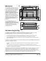
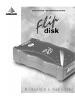
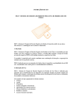
The mounting hole pattern is a
standard for CF1 RecipeCards, and
the front two holes (CF side) line up
with the mounting holes on the
PicoDAQ RecipeCard and many
other RecipeCards.
0.125"
0.600"
20
20
0.125"
2.000"
2.000"
1.400"
0.050"
The BigIDEA sandwiches between
your CF1 and other other electronics
ala PC104 and add about a half inch
to the height of the system. The
drawing at right shows that the
BigIDEA circuit board is larger than
the CF1, and that it juts out far
enough in front to preclude front
panel access to the CompactFlash. In
BigIDEA systems, the CF card is
typically just used as buffer storage
so hopefully this will not be a
problem.
3.000"
2.500"
1.850"
0.132" x4
Mechanics
SAMTEC SSQ-110-23-G-D
SAMTEC SSQ-125-23-G-D
BigIDEA
Recipe
Card
Not Quite Plug & Play
It's unlikely that the IDE drive controller in you PC came with a user's manual or is even
mentioned anywhere in the PC's documentation. PC's can do this because:
1. Their drives and controllers are usually factory installed into convenient drive bays and card cages.
2. The PC BIOS and OS were pre-configured for the installed drive and controller at the factory.
3. PCs don't much care about power or startup time, so they can interrogate hardware peripherals with no
negative consequences.
Though we've tried to make the CF1 mimic the simplicity of a PC, the BigIDEA and hard drives
pose special challenges because:
1. There's no standard mechanical mounting arrangement, so they can't ship pre-configured even if ordered
together.
2. The vast majority of CF1s will never see an add-on drive, so PicoDOS doesn't expect to find one.
3. PicoDOS can't poke around and look for offboard peripherals without incurring startup delays, and in the case
of hard drives, significant power expenditures.
This means you have to learn enough about the BigIDEA and various drive options to correctly
install the hardware and setup the software. Since you've chosen a CF1 and BigIDEA, you
probably do care very much about power utilization and will want to learn everything you can
about the tradeoffs between convenience and simplicity versus maximum battery life.
Persistor BigIDEA Preliminary User's Manual
Copyright © 1999, Persistor Instruments Inc.
Page 2
May 1999
What's in the User's Guide
The remainder of this manual explains how to install, configure, and properly use your BigIDEA
and cards/drive. Part one describes how to connect the BigIDEA between your CF1 and other
peripheral electronics and how to properly setup the board's jumper options for your particular
requirements. Part two describes the cabling from the BigIDEA to you 2.5" drive or PCMCIA
adapter. Part three tells you how to get PicoDOS to recognize the new hardware and takes through
a test run. Part four explains how to make PicoDOS automatically work with BigIDEA drives.
Finally, part five describes the various software techniques you can use to make the most of your
expanded CF1 system.
Packing List
Your BigIDEA ships with the following items:
1
6
1
1
1
1
1
BigIDEA SandwichCard Adapter
2mm configuration jumpers on the BigIDEA with standard default setting
8" 3 connector IDE-44 ribbon cable
18" power cable, tinned leads to 2-pin Molex C-Grid plug
Release Notes
User's Manual (this document)
Update and Examples Diskette (possibly also an update CD)
Read the Release Notes
You must read the printed release notes that shipped with your BigIDEA before attempting to
install or run the hardware. This is where you'll most likely find the information fed back to us by
BigIDEA pioneers, and a quick read could save you much time and frustration.
Persistor BigIDEA Preliminary User's Manual
Copyright © 1999, Persistor Instruments Inc.
Page 3
May 1999
Setting up the BigIDEA
BigIDEAs install sandwich-like between a something and something else. Those something elses
can be a CF1, a RecipeCard, your custom instrument electronics, some other SandwichCard
peripheral, or even more BigIDEAs. Typically, it's a CF1 on top, a BigIDEA in the middle, and a
RecipeCard or your stuff on the bottom. In multiple SandwichCard systems, the stacking order
makes no difference. The remainder of the installation and setup instructions will assume a simple
three board system with a CF1, BigIDEA, and PicoDAQ RecipeCard - though what's described
applies similarly to more complex systems.
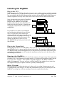
Jumpers
Before you plug your CF1 into the BigIDEA, you should make sure that the three groups of
configuration jumpers are properly installed for your CF1 system. These jumpers select 3.3V or
5V IDE voltage, separate or common power supplies, and the SandwichCard memory slot. All of
these jumpers are accessible when a CF1 is plugged into the BigIDEA, but most other full-sized
SandwichCards will obscure all or some these when they plug into a BigIDEA.
3.3V/5V
The 3.3V/5V jumper J5 comes from the factory preset to the 5 volt position, and
that's where it has to be for hard disk drives, and generally where you want it to be
for flash cards. Flash cards write about 20% faster when operating at 5 volts, but
they pull about 30% less current when you writing at 3.3 volts. However, most
systems don't spend much of time actually writing, so the savings may not be all
that significant.
3
5
J5
Power Source
The power source jumper also comes from the factory installed to let the BigIDEA
use the CF1's VBAT (pin 13) as its source to the switching regulator for the IDE
drives. This is convenient since a single power source and cable works for
everything, but it also means that if the drive turns on and tries to gulp more
power than what's left in your batteries, the CF1 will die when the voltage drops
below about 4 volts. To preclude that possibility, remove the power source jumper
and run a separate supply to connector J1 on the bottom right of the board.
J1
Never connect a separate supply while J1 is jumpered!
Memory Slot
+16
+8 {
SandwichCard
+0
Chip Selects
} +0
74LVC138A
1 of 32 1024 Byte Blocks
+0
+2
+4
+6
+1
+3
+5
+7
The SandwichCard memory slot jumper block
comes pre-configured for slot 0 as shown in the
drawing at right?. If you're constructing a
complex SandwichCard system, refer to the
appendix for details on setting up multiple
SandwichCards, otherwise, just make sure your
BigIDEA looks like the drawing.
+–
The appendix contains much more detail on SandwichCard memory addressing. This is not
required reading for working with the BigIDEA.
Persistor BigIDEA Preliminary User's Manual
Copyright © 1999, Persistor Instruments Inc.
Page 4
May 1999
Installing the BigIDEA
Plug in the CF1
Before plugging in the CF1, lets also make sure we've got a working system as a reference starting
point. Hookup your CF1 and RecipeCard (or whatever) to a power supply and terminal, and make
sure you can get to the PicoDOS prompt and that you have the latest BIOS and PicoDOS firmware
installed. BigIDEAs will only work with version 2.00 or later of both the BIOS and PicoDOS.
Next, disconnect the power and we'll install the
BigIDEA. First, unplug the CF1 from the
RecipeCard (or whatever). Now plug the
backside of the CF1 (the side without the CF
header, but with all 90 pins in a π pattern) into
the topside (component side with sockets) of
the BigIDEA.
It is possible (we've done it) to misalign the
pins and damage both boards if powered that
way (we've proved it), but even the most
cursory visual side-view inspection will reveal
the mistake before any damage can be done - so
make sure to look at it after you insert it. The
drawing at right shows a side view of a
CF1/BigIDEA/RecipeCard system before and
after insertion.
CF1
BigIDEA
PicoDAQ
CF1
BigIDEA
PicoDAQ
Plug in the RecipeCard
Having plugged in the CF1 to the BigIDEA, there's only one way to connect the BigIDEA back
into the RecipeCard - its pins go into the RecipeCard's sockets. We learned our lesson by frying a
CF1/BigIDEA with powered misalignment so we don't know how much harm can be done by not
paying attention. Hopefully you will examine the installation and not have to be the first to call us
with a damage assessment.
Powering the BigIDEA
Whether powered from the CF1 VBAT or the Molex connector, the upper range of the supply must
be limited to 16.5 volts, and the lower range must be 0.5 volts above the operating voltage selected
by J5. One more reminder: Never attach a separate supply to the Molex connector
while J1 is jumpered! There are no fuses, no diode isolation, and nothing else to protect the
two supplies from trying to equalize each other - probably catastrophically!
Quick Checkout
Before going on, let's confirm that what we've done so far is working. Reconnect power and
everything should work exactly as it it did in the preinstallation quick test. This doesn't prove the
BigIDEA is working, but we'll know nothing is seriously wrong with the hookup.
Persistor BigIDEA Preliminary User's Manual
Copyright © 1999, Persistor Instruments Inc.
Page 5
May 1999
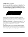
Installing Cards and Drives
Cards and drives connect to the BigIDEA using 44-pin 2mm connectors and 1mm ribbon cables
that can be any length up to twelve inches. The BigIDEA comes with a single eight inch cable with
connectors at both ends, and with one additional connector three inches away from one of the
ends. This one cable actually has many uses. It can be used as a eight inch cable and you can get
rid of the annoying bump in the middle by prying apart and removing the center IDC connector.
You can also make it into either a five inch or three inch cable using just a pair of scissors. You can
also use it to connect two separate single slot PCMCIA adapter boards to the BigIDEA (though
we're not sure why you wouldn't just buy the dual adapter).
3"
5"
The BigIDEA's IDE header is shrouded, but not polarized, and 44-pin IDE cable connectors come
in a variety of widths, so the shroud does not always guarantee proper pin alignment (it does
however with the included cable). Drive headers are neither shrouded nor polarized, so it's ever so
easy to hook them up backwards (goodbye expensive electronics) or misaligned by one set of pins
(poof goes the drive). You must take care to connect pin 1 of the BigIDEA header to pin 1 of the
drive or adapter, and you do this by looking always assigning the striped side of the cable to pin 1.
The BigIDEA tries to help with a block of white silkscreen at the pin 1 side, but most hard drives
give no indication of which side has pin 1. The 44-pin headers on both the BigIDEA and 2.5" hard
drives are not symmetrical along the center of the devices, and in the field, you can figure out
which way to hook them together by centering the BigIDEA board with the drive and noting that
only one orientation gives a straight line connection between the headers.
Bad Vibrations
Neither the BigIDEA or the hard drives have locking mechanisms for the ribbon cable connectors
and rely on the relatively high extraction force of 44 connections to hold the assembly in place.
This works well for desktop, and even laptop computer environments, but it may not be sufficient
to survive high vibration applications. We do not have a generic solution to this potential problem,
but if you suspect your system will operate in a fashion where the cable could be shaken off, you'll
need to do something to keep it attached (wire ties, tak-pak, clamps, etc.).
Persistor BigIDEA Preliminary User's Manual
Copyright © 1999, Persistor Instruments Inc.
Page 6
May 1999
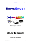
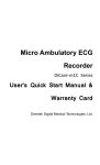
Installing a 2.5" Hard Drive
The BigIDEA makes no provision for physically mounting your 2.5" hard drive other than by
offering a flexible cabling connection. Most modern drives can be installed and operated in any
orientation, but you may need to check with the drive manufacturer for recommendations if you're
pushing the technology limits. Various drives have different limitations on vibration and shock and
these too should be considered when you design the mounting. Hard disk drives self heat when
running (Toshiba MK2104 calls out 15°C maximum rise) so you should also provide for
ventilation if you'll be running at ambient temperatures where that rise could have the drive
working beyond specified limits.
You should also be aware that even though many of the 2.5" drives have similar top or side
mounting holes, these are not standard, or guaranteed to remain the same from one generate of
drives to another - even from the same manufacturer. About all you can count on mechanically is
that 2.5" drives will be 2.75" x 4.0" but that the height may vary from from less than 0.2" to over
0.8".
2.750"
1
2.430"
.113"
.113"
.551"
M3 THD x 4
.130 x .330
3.567"
4.000"
M3 THD x 4
1.500"
4.000"
1
1.375"
2.750"
2.430"
.695" 1.480" .835".535"
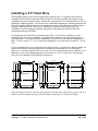
For top mounting drives, we recommend slots instead of holes as shown in the drawing below, far
right. On the left side of the drawing are the mounting hole dimensions for two different 2.5"
drives we've actually worked with. For our own use, we've attached to the drives with M3.0 x 0.5
thd metric screws with a length appropriate to get about 0.1" to 0.2" of the screw into threaded
holes after accounting for board thickness and spacers.
2.430"
These drawings are meant to provide some guidance, but you must confirm these against a drive in
hand or the drive manufacturers specifications before beginning your mechanical design.
Persistor BigIDEA Preliminary User's Manual
Copyright © 1999, Persistor Instruments Inc.
Page 7
May 1999
2.5" Drive Connections
Some 2.5" drives have a separate power connector, but you do not need this with the BigIDEA.
Power for the drives is brought over in the 1mm ribbon cable. Instead of a 44-pin header, most
2.5" drives have a 50-pin header with two pins missing to make one 44-pin header, and one 2x2pin jumper block for drive options (discussed ahead). Most drives also provide little or no
markings to help you properly connect the cable. The dimension drawing above shows how to
identify pin 1 on the drive, and that pin is where you should always connect the striped side of the
ribbon cable.
To save yourself some future catastrophes, this would be an excellent time to make some very clear
markings on the drive where pin 1 is, and where you want the cable stripe to be so that at some
future time, you or your technician will be able to confidently reattach the drive without this longlost BigIDEA manual.
2.5" Master/Slave Options Pins
Most 2.5" drives have another four pins separated from the main group of 44 IDE pins for drive
options. The option pins exist for multiple-drive (Master/Slave) configurations that are not
supported by the BigIDEA. Though this might sound like a cheap and easy way to double your
capacity, the protocol only works by having the two drives up and running, so it's twice the
spinup surge current, and only a bit less than twice the operating current while filling each drive probably not a goal for you CF1 based system. If you need more capacity, consider multiple
BigIDEAs - each powering it's drive independently.
Generally, no jumpers is the correct option for the BigIDEA. If you drive came with jumpers
installed, find out why before running it with the BigIDEA.
Persistor BigIDEA Preliminary User's Manual
Copyright © 1999, Persistor Instruments Inc.
Page 8
May 1999
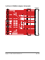
Installing a PCMCIA Adapter Card
To work the BigIDEA with PCMCIA hard disks or
flash cards (including CompactFlash in a PCMCIA
adapter), you need a single or dual PCMCIA to 44pin adapter board. These are actually the same
printed circuit board, but the single has one
PCMCIA header which can work with Type I, II,
or III PCMCIA cards, while the dual has a doubleheight header that can take a Type I or II card in the
lower (slave) socket and a Type I, II, or III card in
the upper (master) socket. The appendix shows the
schematic for the PCMCIA adapter board.
Electrically, the single adapter and the upper socket
of the dual adapter are identical. The single has the advantage of lower height (0.34") versus the
taller (0.62") height of the dual, and the single sells for a little bit less. Dual operation really only
makes sense when using only flash memory cards. The BigIDEA can only power switch the dual
adapter in pairs, so either both are on, or both are off at any given time.
For flash card pairs, that's a small initial startup pulse of current to charge up capacitors and wake
the cards processor, but each settles down to less than 500uA automatically. For hard drive pairs,
that's instead a huge spinup surge current and twice the already onerous operating current. The
combination of a flash card and hard drive in a dual adapter is also unwise since the relatively slow
flash write operations will incur the full penalty of carrying the hard drive power burden over a
long period of time.
Flash memory cards do not care at all about operating orientation, nor do the 512KB and 1GB
Calluna 1.8" drives that we've worked with. If you're using something different, check the
manufacturers data sheets for any restrictions on mounting. Various drives have different
limitations on vibration and shock and these too should be considered when you design the
mounting. Hard disk drives self heat when running so you should also provide for ventilation if
you'll be running at ambient temperatures where that rise could have the drive working beyond
specified limits.
The PCMCIA adapters have a shrouded 44-pin header which is not polarized, so you must take
care to make sure that striped side of the cable connects to pin 1 of the adapter which is marked
with the big white square.
Persistor BigIDEA Preliminary User's Manual
Copyright © 1999, Persistor Instruments Inc.
Page 9
May 1999
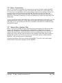
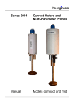
PCMCIA Adapter Dimensions
The BigIDEA makes no provision for physically mounting the PCMCIA adapter board other than
to provide a variety of mounting holes and breakaway panels with additional mounting holes as
shown below.
3.000"
2.875"
2.720"
2.500"
2.375"
.625"
.125"
.490"
.280"
Persistor BigIDEA Preliminary User's Manual
Copyright © 1999, Persistor Instruments Inc.
2.000"
.080" D
1.875"
.130" D
.910"
.610"
.125"
Page 10
May 1999
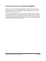
Installing Disk Arrays with Multiple BigIDEAs
Your CF1 can control virtually any number of BigIDEAs to expand the total storage capacity to
record truly huge amounts of data. Each BigIDEA adds only microamps to the idle current and
each BigIDEA powers up its drive independently of other attached drives. However, only one
BigIDEA can be active at any given time.
To install multiple BigIDEAs, simply follow the instructions for installing a single drive/adapter,
but repeat for each BigIDEA in the system. You do not need to modify the jumper settings for each
different BigIDEA, and in fact, all of the BigIDEAs should have identical settings. At startup, the
CF1 interrogates its attached SandwichCards and discovers the unique serial numbers which will
be used to select individual BigIDEAs. The lowest serial number becomes the default BigIDEA for
programs that do not explicitly request a specific unit.
Persistor BigIDEA Preliminary User's Manual
Copyright © 1999, Persistor Instruments Inc.
Page 11
May 1999
Installing BigIDEA Software
Always check the separate BigIDEA release notes for instructions that may supersede these
directions. The release notes will give you up-to-date installation instructions and late breaking
news on any new drives supported by the BigIDEA. Latest copies of the release notes can always
be found on the BigIDEA page of the Persistor Instruments web site http://www.persistor.com.
BigIDEAs require PicoDOS 2.0 (plus patches) or later versions of the CF1 software. PicoDOS 2.0
shipped with partially stubbed APIs for BigIDEA operation and require that you install the latest
CF1.Patch.Lib file into the CF1\Libraries directory. The examples that ship with the BigIDEA
show how to test for valid patch installations and you should copy these techniques in your
software programs.
PicoDOS 2.1 and later Developer's CDs will ship with full driver support for the BigIDEA to
control Persistor Instruments flash cards (CompactFlash and full sized ATA PC Cards), 1.8"
Calluna PCMCIA hard drives (512KB and 1GB), 2.5" Toshiba MKxxxx and IBM Dyla hard
drives, along with generic IDE hard drive support which may or may not work with other IDE
devices.
The BigIDEA may ship with a supplemental diskette containing updated drivers, header files,
documentation, and example programs. Check the release notes, and if required, copy the updated
files to the BigIDEA directory in your development PC at:
MotoCross Support\CF1\Drivers\BigIDEA\
which typically starts at:
C:\Program Files\Metrowerks\CodeWarrior\
Whether installed from the Developer's CD or update diskette, the BigIDEA directory will contain
something like the following files and directories:
BigIDEA\bin\
llformat.pxe low leve format
hdfdisk.pxe
hard drive fdisk partitioning
torture.pxe
hard disk read/write torture tests
BigIDEA\Headers\
BigIDEA\Libraries\
BigIDEA\Docs\
BigIDEA\Examples\
BigIDEA\Stationery\
CF1.BigIDEA\
CF1.BigIDEA(4i)\
Persistor BigIDEA Preliminary User's Manual
Copyright © 1999, Persistor Instruments Inc.
Page 12
May 1999
Getting Started with BigIDEA Software
GigaPicoDOS Example
GigaPicoDOS.mcp in the BigIDEA\Examples directory is a good place to start to familiarize
yourself with the BigIDEA. GigaPicoDOS is based on the "MyPico" stationery (future PicoDOS
2.1) and builds a custom version of PicoDOS that is BigIDEA "aware". It includes all of the
standard PicoDOS commands plus three new commands (ON, OFF, LPSTOP) just for the
BigIDEA. It's main() function sets up your CF1 system to automatically mount a BigIDEA flash
card or hard disk as drive "D", after which you perform all of the normal PicoDOS operations like
DIR, COPY, CHDIR, and so on.
The SetupBigIDEA() helper function shows you what you'll need to do to integrate the BigIDEA
into your own programs, and you can pretty much copy and paste this into your application. The
ON and OFF commands let you power the card/drive on and off, and the LPSTOP command
shows you what to expect when the card/drive is off and the CF1 is in its lowest non-SUSPEND
operating mode.
GigaPicoDOS demonstrates the BigIDEA operations, and gives you an idea of what to expect in
PicoDOS 2.1, but it is not PicoDOS, and it's services are not available when you exit
GigaPicoDOS and return to normal PicoDOS. Until the 2.1 release of PicoDOS, you will have to
incorporate something like the code from the SetupBigIDEA() helper function in each of your
programs that work the BigIDEA.
BigIDEAMax146LPAD
BigIDEAMax146LPAD is a minor variation of the Max146LPFiledAD.c example except that it
copies the CompactFlash data file to a hard disk when the CF card fills up. This simple mechanism
necessitates a pause in the acquisition, but that's the price of the simplicity. You can extend the
functionality by providing two files and ping-ponging between them, or use the methods
demonstrated in the much more complex BigIDEADataLogger example.
BigIDEADataLogger
This builds a low-power, high-capacity data acquisition program from a Persistor CF1 mated to a
BigIDEA hard drive adapters and a single Persistor PRCPDAQ PicoDAQ RecipeCard for the
analog to digital converter and I/O connections. The basic operations and features of the system
are:
Continuous recording of 1 to 8 channels of unipolar analog data in the range or 0 to 2.5 volts.
Sample rates from 50Hz to 1kHz (400sps to 8000sps aggregate).
8-bit (high or low byte) or 16-bit (12 bit resolution) samples.
DOS compatible file system on hard drive for simplified data recovery
Automatic startup and relaunch in the event of a system failure (100 second watchdog).
Three stage data buffering - A-D to RAM, RAM to CompactFlash card, CF to hard drive.
1mA (50Hz/1Ch) to 10mA (1kHz/8Ch) average current drain during acquisition
Password protection to change settings or erase files
This is a much more complex example, and additional documentation can be found in the directory
containing the project file.
Persistor BigIDEA Preliminary User's Manual
Copyright © 1999, Persistor Instruments Inc.
Page 13
May 1999
Using SandwichCards in your CF1 system
Your new BigIDEA add-on for the Persistor CF1 complies with guidelines for standard
SandwichCard peripherals which should make installation and setup a fairly simple and
straightforward process. If the BigIDEA is the only SandwichCard add-on in your CF1 system, or
if the BigIDEA is the only IDE controller SandwichCard add-on, you should be able to safely skip
the rest of this section. If not, you may want to familiarize yourself with some simple
SandwichCard concepts to help you hurdle any installation difficulties.
Your CF1 system can support up to 32 SandwichCards and generally most Persistor Instruments
and third party SandwichCards will be pre-configured to automatically work in your system using
default jumper configurations and default initialization specifiers for their respective software
drivers. This means you usually need to just follow the instructions to copy the associated library
and header files into the proper directories and merge them into your CF1 projects. However,
some very complex CF1 systems may be built with SandwichCard components that compete for
system resources and you will need to manually reconfigure some boards and make minor
accommodations in driver initialization calls to get everything working.
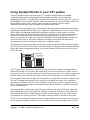
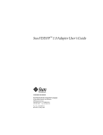
The diagram below shows the pattern and placement of the recommended 2mm chip select jumper
blocks for SandwichCards. Inevitably, some board designs will face physical constraints that make
some other scheme compelling enough to veer from the standard. Electrically however, the effect
will be the same.
+16
+0
+8 {
} +0
74LVC138A
SandwichCard
Chip Selects
1 of 32 1024 Byte Blocks
+0
+2
+4
+6
+1
+3
+5
+7
The CF1 has just two chip selects to provide for system expansion. Without something like the
SandwichCard chip select circuitry, that would limit you to two add-on devices. With it, you can
have up to 32 devices, but at the expense of a large memory space. However, with the exception of
RAM or Flash, almost all I/O devices need only a tiny block of addresses for full functionality.
Each expanded SandwichCard chip select corresponds to a unique block of memory addresses, but
since the C language and supplied drivers means you will almost never need to be cognizant of
these physical addresses, we refer to each expanded chip select by a reference number between 0
and 31. The numerical markings surrounding the jumper blocks combine to yield that value based
on the installed jumpers.
In the diagram above, the top three pins of the jumper block in the upper left chooses which chip
select controls the board. If you jumper the right pin as shown, the system uses CS8 (which you
don't really need to know) and the chip select reference number begins with zero. If the left pin
was jumpered, the system would use CS10 and the reference number would start with sixteen.
The lower six pins select the high or low bank of eight addresses, and the jumpers must always be
moved in pairs (admittedly awkward, but it saves much circuitry) between right as shown for the
Persistor BigIDEA Preliminary User's Manual
Copyright © 1999, Persistor Instruments Inc.
Page 14
May 1999
low address bank with zero added to the chip select reference, or left for the upper bank and eight
added to the reference number.
Finally, the jumper block in the lower right selects one of eight possible slots from the memory
bank. One jumper connects from a center pin to any of the peripheral pins to complete the
selection, and the corresponding number gets added to the reference number to complete its
selection.
Fortunately, most SandwichCards manufacturers will supply their cards pre-configured to conform
to the Persistor Instruments guidelines to simplify installation and setup. The table below details
these selections.
SC#
0
1
2
3
4
5
6
7
8
9
10
11
12
13
14
15
16
17
18
19
20
21
22
23
24
25
26
27
28
29
30
31
Device Class
BigIDEA IDE adapter
other IDE adapter
ATA Flash Card adapter
SCSI adapter
PCMCIA adapter
Quad UART
other UART
Ethernet controller
CAN controller
USB controller
IEEE488 Interface
68k bus to ISA adapter
LCD Display
undefined
undefined
user circuitry
parallel I/O
parallel A-D 1
parallel A-D 2
parallel D-A
counter/timer
Bank-switched RAM
Precision clock
undefined
}
}
}
} reserved for user
} custom circuitry
}
}
}
Base+
0000
0400
0800
0C00
1000
1400
1800
1C00
2000
2400
2800
2C00
3000
3400
3800
3C00
0000
0400
0800
0C00
1000
1400
1800
1C00
2000
2400
2800
2C00
3000
3400
3800
3C00
Size
1024
1024
1024
1024
1024
1024
1024
1024
1024
1024
1024
1024
1024
1024
1024
1024
1024
1024
1024
1024
1024
1024
1024
1024
1024
1024
1024
1024
1024
1024
1024
1024
CS
/CS8
/CS8
/CS8
/CS8
/CS8
/CS8
/CS8
/CS8
/CS8
/CS8
/CS8
/CS8
/CS8
/CS8
/CS8
/CS8
/CS10
/CS10
/CS10
/CS10
/CS10
/CS10
/CS10
/CS10
/CS10
/CS10
/CS10
/CS10
/CS10
/CS10
/CS10
/CS10
Default
FFFF8000
FFFF8400
FFFF8800
FFFF8C00
FFFF9000
FFFF9400
FFFF9800
FFFF9C00
FFFFA000
FFFFA400
FFFFA800
FFFFAC00
FFFFB000
FFFFB400
FFFFB800
FFFFBC00
FFFF0000
FFFF0400
FFFF0800
FFFF0C00
FFFF1000
FFFF1400
FFFF1800
FFFF1C00
FFFF2000
FFFF2400
FFFF2800
FFFF2C00
FFFF3000
FFFF3400
FFFF3800
FFFF3C00
Keep in mind that these are merely guidelines and implementation considerations may persuade
board designers to adopt different strategies. Check the vendors documentation as they will likely
clearly state if you need to be on guard for potential collisions.
Persistor BigIDEA Preliminary User's Manual
Copyright © 1999, Persistor Instruments Inc.
Page 15
May 1999
1-2-Punch PCMCIA Adapter Schematic
1
2
GND
DD3
/RESET
3
4
DD8
5
6
DD9
7
8
9
10
11
12
nc
DD4
DD11
DD5
DD12
DD6
DD13
DD7
DD14
/CS0
DD15
/CS1
DD7
DD6
DD10
DD5
DD11
DD4
JP71
DD12
nc
nc
DD3
13
14
/DIOR
DD13
/DIOW
DD2
DD14
15
16
17
18
19
20 RSVD/A04
nc
21
nc
22
23
24
25
26
27
28
nc
29
nc
30
31
32
nc
nc
nc
nc
nc
DD1
DD15
DD0
GND
INTRQ
JP72
VCC
JP73
C72
0.1uF
CSEL/A03
IORDY
nc
nc
nc
nc
nc
nc
nc
/DIOR
IORDY
nc
nc
/IO16
/RESET
INTRQ
34
JP74
/PDIAG
DA1
35
nc
nc
/DIOW
33
UPPER/ MAST ER
- - SI NGL E- -
L OWER/ SL AV E
I DE
36
JP75
DA2
DA2
DA1
/DASP
DA0
/PDIAG
DD0
DD8
DD1
DD9
DD2
DD10
/IO16
DA0
/CS1
37
38
39
40
41
42
VCC
43
44
nc
/CS0
/DASP
C71
nc
JP76
nc
22uF
GND
Persistor BigIDEA Preliminary User's Manual
Copyright © 1999, Persistor Instruments Inc.
1
35
2
36
3
37
4
38
5
39
6
40
7
41
8
42
9
43
10
44
11
45
12
46
13
47
14
48
15
49
16
50
17
51
18
52
19
53
20
54
21
55
22
56
23
57
24
58
25
59
26
60
27
61
28
62
29
63
30
64
31
65
32
66
33
67
34
68
GND
GND
D03
/CD1
D04
D11
D05
D12
D06
D13
D07
D14
/CE1
D15
A10
/CE2
/OE
/VS1
NC
/IORD
A09
/IOWR
A08
NC
NC
NC
NC
NC
/WE
NC
RY/BS/IRQ
NC
VCC
VCC
VPP
VPP
NC
NC
NC
NC
NC
NC
A07
/CSEL
A06
/VS2
A05
RESET
A04
/WAIT
A03
/INPACK
A02
/REG
A01
BVD2
A00
BVD1
D00
D08
D01
D09
D02
D10
WP/IOIS16
/CD2
GND
GND
nc
nc
nc
PCMCI A
nc
nc
nc
nc
nc
nc
nc
nc
JP77
nc
nc
nc
nc
nc
nc
nc
nc
nc
1
35
2
36
3
37
4
38
5
39
6
40
7
41
8
42
9
43
10
44
11
45
12
46
13
47
14
48
15
49
16
50
17
51
18
52
19
53
20
54
21
55
22
56
23
57
24
58
25
59
26
60
27
61
28
62
29
63
30
64
31
65
32
66
33
67
34
68
GND
GND
D03
/CD1
D04
D11
D05
D12
D06
D13
D07
D14
/CE1
D15
A10
/CE2
/OE
/VS1
NC
/IORD
A09
/IOWR
A08
NC
NC
NC
NC
NC
/WE
NC
RY/BS/IRQ
NC
VCC
VCC
VPP
VPP
NC
NC
NC
NC
NC
NC
A07
/CSEL
A06
/VS2
A05
RESET
A04
/WAIT
A03
/INPACK
A02
/REG
A01
BVD2
A00
BVD1
D00
D08
D01
D09
D02
D10
WP/IOIS16
/CD2
GND
GND
Page 16
May 1999