1
WIAS-3200N v2
802.11n Internet Access
Server
User’s Manual
Table of Contents
Copyright & Disclaimer
No part of this publication may be reproduced in any form or by any means, whether
electronic, mechanical, photocopying, or recording without the written consent of OvisLink
Corp.
OvisLink Corp. has made the best effort to ensure the accuracy of the information in this
user’s guide. However, we are not liable for the inaccuracies or errors in this guide.
Please use with caution. All information is subject to change without notice
All Trademarks are properties of their respective holders.
i
AirLive WIAS-3200N v2 User’s Manual
Table of Contents
FCC Statement
Federal Communication Commission Interference Statement
This equipment has been tested and found to comply with the limits for a Class B digital
device, pursuant to Part 15 of the FCC Rules. These limits are designed to provide
reasonable protection against harmful interference in a residential installation. This
equipment generates uses and can radiate radio frequency energy and, if not installed and
used in accordance with the instructions, may cause harmful interference to radio
communications. However, there is no guarantee that interference will not occur in a
particular installation. If this equipment does cause harmful interference to radio or
television reception, which can be determined by turning the equipment off and on, the
user is encouraged to try to correct the interference by one of the following measures:
Reorient or relocate the receiving antenna.
Increase the separation between the equipment and receiver.
Connect the equipment into an outlet on a circuit different from that to which the
receiver is connected.
Consult the dealer or an experienced radio/TV technician for help.
FCC Caution
Any changes or modifications not expressly approved by the party responsible for
compliance could void the user's authority to operate this equipment. This device complies
with Part 15 of the FCC Rules. Operation is subject to the following two conditions: (1) This
device may not cause harmful interference, and (2) this device must accept any
interference received, including interference that may cause undesired operation. For
product available in the USA/Canada market, only channel 1~11 can be operated.
Selection of other channels is not possible.
This device and its antenna(s) must not be co-located or operation in conjunction with any
other antenna or transmitter.
FCC Radiation Exposure Statement
This equipment complies with FCC radiation exposure limits set forth for an uncontrolled
environment. This equipment should be installed and operated with minimum distance
20cm between the radiator & your body.
AirLive WIAS-3200N v2 User’s Manual
ii
Table of Contents
Table of Contents
1.
BEFORE YOU START................................................................................................ 1
1.1
1.2
2.
PREFACE.............................................................................................................................................. 1
PACKAGE CHECKLIST ............................................................................................................................ 2
GETTING STARTED WITH EASY SETUP UTILITY................................................... 3
2.1
INTRODUCE .......................................................................................................................................... 3
2.2
SYSTEM CONCEPT ................................................................................................................................ 3
2.3
HARDWARE DESCRIPTIONS ................................................................................................................... 4
2.3.1 Front Panel .................................................................................................................................. 4
2.3.2 Rear Panel................................................................................................................................... 5
2.3.3 Top LED Panel............................................................................................................................. 6
2.4
SYSTEM REQUIREMENT......................................................................................................................... 7
2.5
INSTALLATION STEPS ............................................................................................................................ 7
2.6
EASY SETUP......................................................................................................................................... 8
2.7
ACCESS W EB MANAGEMENT INTERFACE .............................................................................................. 10
3.
CONFIGURE HOTSPOT TO NETWORK ................................................................. 13
3.1
NETWORK REQUIREMENT.................................................................................................................... 13
3.2
WAN ................................................................................................................................................. 13
3.2.1 Static IP ..................................................................................................................................... 13
3.2.2 Dynamic IP ................................................................................................................................ 14
3.2.3 PPPoE ....................................................................................................................................... 14
3.2.4 PPTP ......................................................................................................................................... 15
3.2.5 DNS ........................................................................................................................................... 15
3.2.6 MAC Clone ................................................................................................................................ 16
3.3
WAN TRAFFIC .................................................................................................................................... 16
3.3.1 Load Balance............................................................................................................................. 17
3.3.2 Backup....................................................................................................................................... 17
3.3.3 Connection Detect ..................................................................................................................... 17
3.4
LAN/VLAN ........................................................................................................................................ 19
3.4.1 VLAN Setup............................................................................................................................... 19
3.4.2 LAN/VLAN List........................................................................................................................... 19
3.4.3 LAN Setup (Domain0) ............................................................................................................... 20
3.4.4 VLAN Setup (Domain1-3).......................................................................................................... 20
3.4.5 Bandwidth Control ..................................................................................................................... 20
3.4.6 DHCP Server ............................................................................................................................. 23
3.4.7 Static Lease List ........................................................................................................................ 24
3.5
DYNAMIC DNS ................................................................................................................................... 24
3.6
MANAGEMENT .................................................................................................................................... 25
3.6.1 System Information.................................................................................................................... 26
3.6.2 Root Password .......................................................................................................................... 26
3.6.3 Admin Password........................................................................................................................ 26
3.6.4 Operator Password.................................................................................................................... 27
3.6.5 Login Methods ........................................................................................................................... 27
3.6.6 E-mail SMTP Relay ................................................................................................................... 28
3.6.7 Ping Watchdog .......................................................................................................................... 29
3.7
TIME SERVER ..................................................................................................................................... 30
3.7.1 System Time.............................................................................................................................. 30
3.7.2 Setup Time Use NTP................................................................................................................. 30
3.7.3 User Setup................................................................................................................................. 31
3.7.4 Time Display Format ................................................................................................................. 31
3.8
SNMP ............................................................................................................................................... 32
iii
AirLive WIAS-3200N v2 User’s Manual
Table of Contents
3.8.1
3.8.2
3.8.3
4.
SNMP v2c.................................................................................................................................. 32
SNMP v3.................................................................................................................................... 32
SNMP Trap ................................................................................................................................ 32
CONFIGURE SERVICE DOMAIN............................................................................. 33
4.1
SERVICE DOMAIN................................................................................................................................ 33
4.1.1 Service Domain ......................................................................................................................... 34
4.2
AUTHENTICATION ................................................................................................................................ 37
4.2.1 Authentication Management...................................................................................................... 37
4.2.2 Pregenerate Ticket .................................................................................................................... 38
4.2.3 On-Demand ................................................................................................................................45
4.2.3.1 Billing Plan Setup ...................................................................................................................................50
4.2.3.2 Payment Gateway ..................................................................................................................................53
4.2.3.3 Thermal Printer Setup ............................................................................................................................56
4.2.3.4 Billing Plan Report ..................................................................................................................................60
4.2.3.5 Ticket Customization ..............................................................................................................................62
4.2.4 Local RADIUS Accounts............................................................................................................63
4.2.5 Remote RADIUS Accounts........................................................................................................67
4.2.6 Clear Tickets..............................................................................................................................68
4.3
PRIVILEGE IP/MAC ADDRESS .............................................................................................................68
4.4
WALLED GARDEN ...............................................................................................................................69
4.5
BLACKLIST..........................................................................................................................................71
4.6
NOTIFICATION.....................................................................................................................................72
4.7
ONLINE USERS ...................................................................................................................................77
4.8
LOG INFO ...........................................................................................................................................78
5.
CONFIGURE WIRELESS CONNECTION ................................................................ 80
5.1
GENERAL SETUPS .............................................................................................................................. 80
5.2
ADVANCED SETUP .............................................................................................................................. 82
5.3
VIRTUAL AP SETUP ............................................................................................................................. 85
5.3.1 VAP0-3 Setup ............................................................................................................................ 86
5.3.1.1 Security ..................................................................................................................................................87
5.3.1.2 WDS .......................................................................................................................................................93
5.3.2 Wireless MAC Filter................................................................................................................... 94
5.4
ASSOCIATED CLIENTS ......................................................................................................................... 96
5.5
WDS STATUS ..................................................................................................................................... 97
6.
ADVANCE FUNCTIONS ........................................................................................... 98
6.1
6.2
6.3
6.4
6.5
7.
NETWORK UTILITIES............................................................................................ 104
7.1
7.2
7.3
7.4
7.5
8.
DMZ.................................................................................................................................................. 98
IP FILTER ........................................................................................................................................... 98
MAC FILTER..................................................................................................................................... 100
VIRTUAL SERVER .............................................................................................................................. 101
TIME POLICY .................................................................................................................................... 102
PROFILE SETTING (BACKUP/RESTORE AND RESET TO FACTORY)......................................................... 104
FIRMWARE UPGRADE ........................................................................................................................ 105
NETWORK UTILITY ............................................................................................................................ 105
FORMAT DATABASE ........................................................................................................................... 107
REBOOT ........................................................................................................................................... 108
VIEW SYSTEM LOG & STATUS ............................................................................ 109
8.1
8.2
8.3
OVERVIEW........................................................................................................................................ 109
EXTRA INFO ..................................................................................................................................... 110
EVENT LOG.................................................................................................................................. .... 113
APPENDIX A. SPECIFICATIONS .................................................................................. 114
AirLive WIAS-3200N v2 User’s Manual
iv
Table of Contents
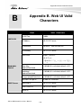
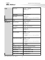
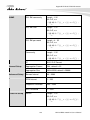
APPENDIX B. WEB UI VALID CHARACTERS.............................................................. 122
APPENDIX C. SYSTEM MANAGER PRIVILEGES........................................................ 131
APPENDIX D. CREATE PAYPAL BUSINESS ACCOUNT............................................ 133
APPENDIX E. EXAMPLE OF MAKING PAYMENTS FOR END USERS ....................... 137
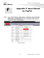
APPENDIX F. ISSUE REFUND FOR PAYPAL ............................................................... 141
APPENDIX G. NETWORK CONFIGURATION ON PC & USER LOGIN ........................ 145
APPENDIX H. USING STB CONNECTOR FOR POWER INPUT ................................... 164
v
AirLive WIAS-3200N v2 User’s Manual
1. Before You Start
1
1. Before You Start
1.1 Preface
This manual is for WLAN service providers or network administrators to set up a network
environment using the hotspot system. It contains step-by-step procedures and graphic
examples to guide MIS staff or individuals with slight network system knowledge to
complete the installation.
1
AirLive WIAS-3200N v2 User’s Manual
1. Before You Start
1.2 Package Checklist
The standard package of WIAS-3200N v2 includes:
WIAS-3200N v2 x 1
CD-ROM (with User’s Manual and QIG) x 1
Quick Installation Guide (QIG) x 1
Ethernet Cable x 1
Power Adapter (DC 12V,1A) x 1
Antenna x 2
Ground Cable x 1
*Note: It is highly recommended to use all the supplies in the package instead of
substituting any components by other suppliers to guarantee bests performance.
AirLive WIAS-3200N v2 User’s Manual
2
2 Getting Started with Easy Setup Utility
2
2. Getting Started with Easy
Setup Utility
2.1 Introduce
The WIAS-3200N v2 is the most economical and feature rich Wireless Hotspot Gateway,
targeting mini-size stores that want to provide small, single-point wireless Internet access
service. WIAS-3200N v2 is a perfect choice for beginners to run hotspot businesses. It
does not cost much compared to buying a pile of equipments, nor does it take the skills of
an expert to glue multiple applications out of multiple freeware. Feature-packed for hotspot
operation, WIAS-3200N v2 comes with built-in 802.11 n/b/g MIMO access point, web
server and web pages for clients to login, easy logo-loading for branding a hotspot store,
simple user/visitor account management tool, payment plans, credit card gateway, traffic
logs, IP sharing , Firewall, Multi-WAN and Qos etc.
One single WIAS-3200N v2 can serve up to 100 simultaneous users, takes control over
authentication, authorization, accounting and routing to the Internet as well as to the
operating central. Built-in AAA system allows hotspot owners set up public access services
without extra RADIUS server.
WIAS-3200N v2 also brings in an extra advantage - the wall-mountable, dust-proof (IP50)
metal housing.
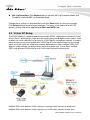
2.2 System Concept
WIAS-3200N v2 is capable of managing user authentication, authorization and accounting.
The user account information is stored in the local database or a specified external
RADIUS database server. Featured with user authentication and integrated with external
payment gateway, WIAS-3200N v2 allows users to easily pay the fee and enjoy the
Internet service using credit cards through a variety of payment gateways including PayPal.
Furthermore, WIAS-3200N v2 introduces the concept of Zones – Private Zone and Public
Zone, each with its own definable access control profiles. Private Zone means clients are
not required to be authenticated before using the network service. On the other hand,
clients in Public Zone are required to get authentication before using the network service.
This is very useful for hotspot owners seeking to deploy wireless network service for clients
and manage the network as well. The following diagram is an example of WIAS-3200N v2
set to manage the Internet and network access services at a hotspot venue.
3
AirLive WIAS-3200N v2 User’s Manual
2. Getting Started with Easy Setup Utility
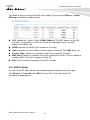
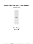
2.3 Hardware Descriptions
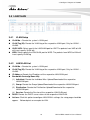
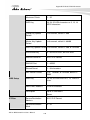
2.3.1
Front Panel
No.
Connector
Description
1
USB
For future usage only.
2
Scan Button
There are two functions for Scan button as following.
Scan New Channel
Press and hold the Scan button for 3 seconds until
STATUS LED FLASH and release to Scan New AP's
Channel.
AirLive WIAS-3200N v2 User’s Manual
4
2 Getting Started with Easy Setup Utility
Reset to factory default
Press and hold the Scan button for more than 10
seconds until SYSTEM LED FLASH to reset the system
to default configurations.
3
Console
Attach the RS-232 console cable here, for management use
only.
4
WAN1/WAN2
Attach Ethernet cables here for connecting to the wired local
network. LAN1 maps to Private Zone and requires no user
authentication, LAN2 maps to Public Zone and by default
requires user authentication.
5
LAN (PoE)
Attach the wired external network here. This port supports
Power over Ethernet (PoE) for flexible installation.
6
Reset
This is hardware reset button. Press once to restart the
system.
7
STB Connector for
Power Apply
For connecting power input via STB, please refer “Appendix
H. Using STB connector for power input” for more detail.
8
Power Socket
For connecting to external power supply via the power
adapter.
(12VDC/1A)
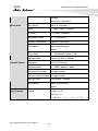
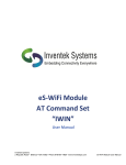
2.3.2
Rear Panel
Connector
Antenna Connector
Description
Attach antennas here. WIAS-3200N v2 supports 1 RF
interface with 2 SMA connectors.
5
AirLive WIAS-3200N v2 User’s Manual
2. Getting Started with Easy Setup Utility
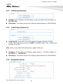
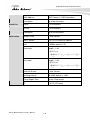
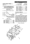
2.3.3
No.
Top LED Panel
Connector
Description
1
Power
LED ON indicates power on; OFF indicates power off.
2
LAN
LED ON indicates LAN connection; OFF indicates no connection;
BLINKING indicates transmitting data.
3
WAN2
4
WAN1
LED ON indicates WAN connection; OFF indicates disconnection;
BLINKING indicates transmitting data.
5
WLAN
LED ON indicates wireless ready.
6
PRINT
LED ON thermal ticket printer is ready.
7
SYSTEM
LED ON/FLASH indicates Flash busy, OFF indicates Flash Idle
8
Status
LED ON indicates System up, OFF indicates down, FLASH
indicates Scan button activated.
AirLive WIAS-3200N v2 User’s Manual
6
2 Getting Started with Easy Setup Utility
2.4 System Requirement
Standard 10/100BaseT including network cables with RJ-45 connectors
All PCs need to install the TCP/IP network protocol
2.5 Installation Steps
Please follow the steps below to install WIAS-3200N v2:
Please follow the steps mentioned below to install the hardware of WIAS-3200N v2:
Step 1. Place the WIAS-3200N v2 at a best location.
The best location for WIAS-3200N v2 is usually at the center of your wireless network.
Step 2. Connect WIAS-3200N v2 to your outbound network device.
Connect one end of the Ethernet cable to the WAN port of WIAS-3200N v2 on the front
panel. Depending on the type of internet service provided by your ISP, connect the other
end of the cable to the ATU-Router of an ADSL, a cable modem, a switch or a hub. The
WAN LED indicator should be ON to indicate a proper connection.
Step 3. Connect WIAS-3200N v2 to your network device.
Connect one end of the Ethernet cable to the LAN port of WIAS-3200N v2 on the front
panel. Connect the other end of the cable to a PC for configuring the system. The LAN LED
indicator should be ON to indicate a proper connection.
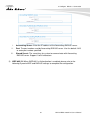
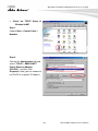
1. There are two ways to supply power over to WIAS-3200N v2.
(a) Connect the DC power adapter to the WIAS-3200N v2 power socket on the front
panel.
(b) WIAS-3200N v2 is capable of transmitting DC current via its WAN PoE port.
Connect an IEEE 802.3af-compliant PSE device, e.g. a PoE-switch, to the WAN
port of WIAS-3200N v2 with the Ethernet cable.
2. Now, the hardware installation is completed.
*Caution!! Please only use the power adapter supplied with the WIAS-3200N v2 package.
Using a different power adapter may damage this system.
7
AirLive WIAS-3200N v2 User’s Manual
2. Getting Started with Easy Setup Utility
*Caution!! To double verify the wired connection between WIAS-3200N v2 and your
switch/router/hub, please check the LED status indication of these network devices.
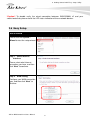
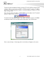
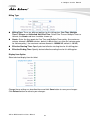
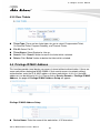
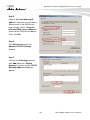
2.6 Easy Setup
Web UI Wizard
Please click the System >
Wizard to start the setup wizard.
Step 1. Select Internet
Interface
Please select what internet
connection you have, and then
click “Next” to continue.
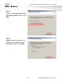
Step 2. WAN Setting
Configure your WAN connection
type, and then click “Next” to
continue.
AirLive WIAS-3200N v2 User’s Manual
8
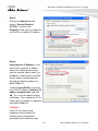
2 Getting Started with Easy Setup Utility
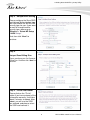
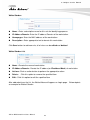
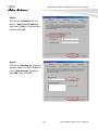
Step 3. Hotspot Zone Setting
Please configure the Zone SSID
and Hotspot Authentication type.
We have choice the WPA2-PSK
security type for you. If you want
to want to change to other
security type, please go to
"Wireless > Virtual AP Setup
>VAP0 Setup".
And, then click “Next” to
continue.
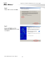
Step 4.
Hotspot Zone Billing Plan
Please configure your On-Demand
Billing Plan, and then click “Next” to
continue.
Step 5. Finish and Reboot
Please click on the "Finish"
button if you have entered all the
information correctly. It will take
about 2 minutes to reboot. After
reboot, you will use the SSID
you entered, and please select
the SSID and connect it.
9
AirLive WIAS-3200N v2 User’s Manual
2. Getting Started with Easy Setup Utility
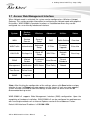
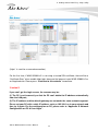
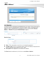
2.7 Access Web Management Interface
When Hotspot mode is activated, the system can be configured as a Wireless Hotspot
Gateway. This section provides information in configuring the Hotspot mode with graphical
illustrations. WIAS-3200N v2 provides functions as stated below where they can be
configured via a user-friendly web based interface.
System
Service
Domain
Wireless
Advanced
Utilities
Status
WAN
Service
Domain
General
Setup
DMZ
Profile Setting
Overview
WAN Traffic
Authentication
Advanced
Setup
IP Filter
Firmware
Upgrade
Extra Info
LAN/VLAN
Privilege List
Virtual AP
Setup
MAC Filter
Network
Utility
Event Log
DDNS
Walled
Garden
Associated
Clients
Virtual Server
Format
Database
Management
Notification
WDS Status
Time Policy
Reboot
Time Server
Online Users
SNMP
Log Info
*Note: After finishing the configuration of the settings, please click Save button and pay
attention to see if a Reboot message appears on the screen. If such message appears,
system must be restarted to allow the settings to take effect. All online users will be
disconnected during restart.
WIAS-3200N v2 supports Web Management Interface (WMI) configuration. Upon the
completion of hardware installation, WIAS-3200N v2 can be configured via web browsers
with JavaScript enabled such as Internet Explorer version 6.0 and above or Firefox.
Default LAN interface IP address is 192.168.1.254.
AirLive WIAS-3200N v2 User’s Manual
10
2 Getting Started with Easy Setup Utility
To access the web management interface, connect a PC to the LAN Port, and then launch
a browse. Make sure you have set DHCP in TCP/IP of your PC to get an IP address
dynamically. The default gateway IP address is the default gateway IP address of Private
Zone: “192.168.1.254”.
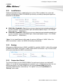
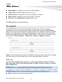
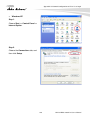
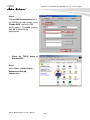
Next, enter the gateway IP address of WIAS-3200N v2 at the address field. The default
gateway IP address from LAN Port is http://192.168.1.254.
The administrator login page will appear. Enter “root”, the default username, and “airlive”,
the default password, in the User Name and Password fields. Click LOGIN to log in.
After a successful login, a “Home” page with six main buttons will appear on the screen.
11
AirLive WIAS-3200N v2 User’s Manual
2. Getting Started with Easy Setup Utility
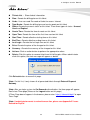
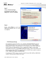
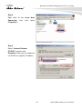
(“https” is used for a secured connection).
For the first time, if WIAS-3200N v2 is not using a trusted SSL certificate, there will be a
“Certificate Error” when enable https login, because the browser treats WIAS-3200N v2 as
an illegal website. Please press “Continue to this website” to continue.
*Caution!!!
If you can’t get the login screen, the reasons may be:
(1) The PC is set incorrectly so that the PC can’t obtain the IP address automatically
from the LAN port;
(2) The IP address and the default gateway are not under the same network segment.
Please set your PC with a static IP address such as 192.168.1.xx in your network and
then try it again. For the configuration on PC, please refer to “Appendix G. Network
Configuration on PC & User Login”.
AirLive WIAS-3200N v2 User’s Manual
12
3 Configure Hotspot to Network
3
3. Configure Hotspot to
Network
3.1 Network Requirement
In the general network environment, the main role of WIAS-3200N v2 is a gateway that
manages all the network access from internal network to Internet. Thus, the first step is to
prepare an Internet connection from your ISP (Internet Service Provider) and connect it to
the WAN port of WIAS-3200N v2.
3.2 WAN
There are 3 connection types for the WAN Port: Static IP, Dynamic IP, PPPoE and PPTP.
Now, let us discuss how to configure WAN port. Please click on System > WAN and follow
the below setting.
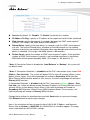
3.2.1
Static IP
The administrator can manually setup the WAN IP address when static IP is available/
preferred.
13
AirLive WIAS-3200N v2 User’s Manual
3. Configure Hotspot to Network
IP Address: The IP address of the WAN port.
IP Netmask : The Subnet mask of the WAN port.
IP Gateway: The IP address of the host router which resides on the external network
and provides the point of connection to the next hop towards the Internet. This can be
a DSL modem, Cable modem, or a WISP gateway router. AC-920X will direct all the
packets to the gateway if the destination host is not within the local network.
Gateway IP address should be from the same address space (on the same network
segment) as the AC-920X's external network interface.
3.2.2
Dynamic IP
This configuration type is applicable when the WIAS-3200N v2 is connected to a network
with the presence of a DHCP server; all related IP information will be provided by the
DHCP server automatically. If the IP Address does not assigned from DHCP server, the
system need manual connect to DHCP server.
Hostname : The Hostname of the WAN port
3.2.3
PPPoE
This configuration type is applicable when the WIAS-3200N v2 is connected to a network
with the presence of a PPPoE server.
User Name : Enter User Name for PPPoE connection
Password : Enter Password for PPPoE connection
MTU: MTU stands for Maximum Transmission Unit. For PPPoE connections, you may
need to set the MTU setting in order to work correctly with your ISP. Default is 1492
bytes.
AirLive WIAS-3200N v2 User’s Manual
14
3 Configure Hotspot to Network
3.2.4
PPTP
The Point-to-Point Tunneling Protocol (PPTP) mode enables the implementation of secure
multi-protocol Virtual Private Networks (VPNs) through public networks.
Username : Enter User Name for PPTP connection .(You can set 0-32 alphanumeric
and ~!@#$%^*()_+-:<>?[]/;,.= specific characters)
Password: Enter Password for PPTP connection. (You can set 0-32 alphanumeric
and ~!@#$%^*()_+-:<>?[]/;,.= specific characters)
PPTP Server IP Address : The IP address of the PPTP server
My WAN IP : The IP address of the WAN port
My WAN IP Netmask : The Subnet mask of the WAN port
MTU: The range is 1400-1460, default is 1460 bytes. MTU stands for Maximum
Transmission Unit. Consult with WISP for a correct MTU setting.
MPPE Encryption: Microsoft Point-to-Point Encryption (MPPE) encrypts data in
Point-to-Point Protocol (PPP)-based dial-up connections or Point-to-Point Tunneling
Protocol (PPTP) virtual private network (VPN) connections. 128-bit key (strong) and
40-bit key (standard) MPPE encryption schemes are supported. MPPE provides data
security for the PPTP connection that is between the VPN client and the VPN server.
3.2.5
DNS
You can select “No Default DNS Server” or “Specify DNS Server IP” radial button as
desired to set up system DNS.
Primary: The IP address of the primary DNS server.
Secondary: The IP address of the secondary DNS server.
15
AirLive WIAS-3200N v2 User’s Manual
3. Configure Hotspot to Network
3.2.6
MAC Clone
The MAC address is a 12-digit HEX code uniquely assigned to hardware as identification.
Some ISPs require you to register a MAC address in order to access to Internet. If not, you
could use default MAC or clone MAC from a PC.
Keep Default MAC Address: Keep the default MAC address of WAN port on the
system.
Clone MAC Address: If you want to clone the MAC address of the PC, then click the
“Clone MAC Address” button. The system will automatically detect your PC's MAC
address.
* Note: The Clone MAC Address field will display MAC address of the PC connected to
system. Click Save button can make clone MAC effective.
Manual MAC Address: Enter the MAC address registered with your ISP.
Change these settings as described here and click Save button to save your changes.
Click Reboot button to activate your changes
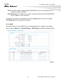
3.3 WAN Traffic
The section is for administrators to configure the control over the entire system’s traffic
though the WAN interface (WAN1 and WAN2 ports). To configure WAN Traffic, please go
to: System > WAN Traffic.
Primary WAN Interface: Select desired primary WAN interface for system.
Traffic Mode: There are three types: None, Load Balance and Backup.
AirLive WIAS-3200N v2 User’s Manual
16
3 Configure Hotspot to Network
3.3.1
Load Balance
Outbound load balancing is supported by the system. When enabled, the system will
allocate traffic between WAN1 and WAN2 dynamically according to designed algorithms
based on the Bandwidth.
WAN1 Max. Bandwidth: Specify the maximum download and upload bandwidth that
can be shared by clients of the WAN1 port.(Download/Upload range is 128-102400
Kbit/s, default is 10240 Kbit/s)
WAN2 Max. Bandwidth: Specify the maximum download and upload bandwidth that
can be shared by clients of the WAN2 port. (Download/Upload range is 128-102400
Kbit/s, default is 10240 Kbit/s)
* Note: On the Load Balance traffic mode, the primary WAN port is WAN1. When the
WAN1 connection is down, the WAN2 will backup automatically.
3.3.2
Backup
When primary WAN interface is WAN1 and WAN2 is available, WAN1's traffic will be routed
to WAN2 when WAN1 connection is down. When WAN1 connection is up, the route traffic
will be connected back to WAN1 automatically.
3.3.3
Connection Detect
The Connect Detect sets the WIAS-3200N v2 to continuously ping a user defined IP
address (it can be the Internet gateway for example). If it is unable to ping under the user
defined constraints, the WIAS-3200N v2 t will change Primary WAN interface to
secondary WAN interface automatically. This option is only for “Load Balance” or
“Backup” traffic mode.
17
AirLive WIAS-3200N v2 User’s Manual
3. Configure Hotspot to Network
Service: By default, it's “Disable”. To “Enable” to activate this function.
IP Address To Ping : specify an IP address of the target host which will be monitored
Ping Interval: specify time interval (in seconds) between the ICMP “echo requests”
are sent. (The range is 60-3600, default is 60 seconds.)
Startup Delay: specify initial time delays (in seconds) until first ICMP “echo requests”
are sent. The value of Startup Delay should be at least 60 seconds as the network
interface and wireless connection initialization takes considerable amount of time if the
device is rebooted. (The range is 60-3600, default is 60 seconds.)
Failure Count: specify the number of ICMP “echo response” replies. If the specified
number of ICMP “echo response” packets is not received continuously, the primary
WAN traffic will be routed secondary WAN. (The range is 1-99, default is 1.)
* Note: If Connection Detect is disabled on “Load Balance” or “Backup”, the system will
use default value.
* Note: if “Connection Detection” is disabled and the PHY's connection status shows Red
(Status > Port Link Info). The system will detect PHY on every 5 seconds. When system
detects failure 1 times, the traffic of package will routed via Secondary WAN Interface.
When Primary WAN Interface detects 1 time success, the traffic of package will routed via
Primary WAN Interface.
If “Connection Detection” is disabled and the PHY's connection is Green (Status > Port
Link Info), the system will detect remote Gateway IP address of Primary WAN on every 5
seconds. When system detects failure 3 times, the traffic of package will routed via
Secondary WAN Interface. When Primary WAN Interface detects 1 time success, the
traffic of package will routed via Primary WAN Interface.
Change these settings as described here and click Save button to save your changes.
Click Reboot button to activate your changes
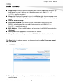
Here is the instruction for how to setup the local LAN/VLAN IP Address and Netmask.
Please click on System > LAN/VLAN, the LAN/VLAN List should be appear. This page
shows information of LAN's/VLAN's settings.
AirLive WIAS-3200N v2 User’s Manual
18
3 Configure Hotspot to Network
3.4 LAN/VLAN
3.4.1
VLAN Setup
VLAN No. : Denote the system's VLAN port.
VLAN Tag (ID): Denote the VLAN tag of the respective VLAN port. Only for VLAN1 ~
VLAN3.
VAP0-VAP3: Select specify the LAN/VLAN port for VAP. The packets from VAP to LAN
will insert specify VLAN tag
WDS: Select specify the LAN/VLAN port for WDS. The packets from WDS to LAN will
insert specify VLAN tag
3.4.2
LAN/VLAN List
VLAN No. : Denote the system's VLAN port.
VLAN Tag (ID): Denote the VLAN tag of the respective VLAN port. Only for VLAN1 ~
VLAN3.
IP Address: Denote the IP address of the respective LAN/VLAN port.
Bandwidth Control(p/Down Kb):
(1) Individual: Denote the Individual Max. Upload/Download of the respective
LAN/VLAN port.
(2) Group: Denote the Group Upload/Download of the respective LAN/VLAN port.
(3) Distribution: Denote the Distribution Upload/Download of the respective
LAN/VLAN port.
(4) Session: Denote the Session of the respective LAN/VLAN port.
DHCP: Denote the DHCP server status of the respective LAN/VLAN.
Actions: Click this option to configure LAN/VLAN's settings, the setup page should be
appear.
Below depicts an example for LAN.
19
AirLive WIAS-3200N v2 User’s Manual
3. Configure Hotspot to Network
3.4.3
LAN Setup (Domain0)
IP Address: The IP address of the LAN port, and the he default LAN's IP address as
192.168.1.254,
IP Netmask : The Subnet mask of the VLAN port; default Netmask is 255.255.255.0
3.4.4
VLAN Setup (Domain1-3)
VLAN Tag (ID): Virtual LAN, the system supports 3 tagged VLAN port (VLAN1 ~
VLAN3). The valid values are from 1 to 4094. The default VLAN1's tag ~ VLAN3's tag
are from 101 to 103.
*Note: Some system and VLAN switch do not support VLAN tag 1
IP Address: The IP address of VLAN port, default VLAN1's ~ VLAN3's IP address as
192.168.101.1 ~ 192.168.103.1.
IP Netmask : The Subnet mask of the VLAN port; default Netmask is 255.255.255.0
3.4.5
Bandwidth Control
AirLive WIAS-3200N v2 User’s Manual
20
3 Configure Hotspot to Network
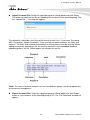
Bandwidth Control: By default, it's “Disable”. To “Enable” to use bandwidth control.
Type : Enable the desire option among “Even Distribution of Bandwidth” or
“Individual Bandwidth”
(1) Even Distribution of Bandwidth: Set users distribute Total Max. Upload/Download.
Below depicts an example for Even Distribution of Bandwidth, set Total Max.
Upload or Download to 9 Mbps, if one user access Internet, the maximum upload or
download is 9 Mbps; if three users access Internet at the same time, the maximum
upload or download is 3 Mbps by each user.
Total Max. Upload: The Total Max. Upload is in the range of 0~102400 Kbit/s, 0
indicates unlimited, default is 512 Kbit/s
Total Max. Download: The Total Max. Download is in the range of 0~102400 Kbit/s, 0
indicates unlimited; default is 512 Kbit/s.
*Note: If the system does not enable any authentication function, all users of the
bandwidth control will be based by the “Total Max. Upload” and “Total Max. Download”
If the system enable authentication function and user in the privilege list, the user of
bandwidth will be uncontrolled by Even Distribution of Bandwidth
(2) Individual Bandwidth: Set each users Individual Upload/Download. Below depicts an
example for Individual Bandwidth, set Group Upload or Download to 6 Mbps and
Individual Upload or Download to 3 Mbps, if one user access Internet, the maximum
upload or download is 3 Mbps; if three users access Internet at the same time, the
maximum upload or download is 3 Mbps by each user.
21
AirLive WIAS-3200N v2 User’s Manual
3. Configure Hotspot to Network
Individual Upload : The Individual Upload is in the range of 0~102400 Kbit/s, 0
indicates unlimited, default is 512 Kbit/s
Individual Download : The Individual Download is in the range of 0~102400 Kbit/s, 0
indicates unlimited, default is 512 Kbit/s
Group Total Limit:
Limit.
Group Upload : The Group Upload is in the range of 0~102400 Kbit/s, 0 indicates
unlimited, default is 512 Kbit/s
Group Download : The Group Download is in the range of 0~102400 Kbit/s, 0
indicates unlimited, default is 512 Kbit/s
By default, it's “Disable”. To “Enable” to activate Group Total
AirLive WIAS-3200N v2 User’s Manual
22
3 Configure Hotspot to Network
*Note: If the system enable authentication function and user in the privilege list,
of bandwidth will be uncontrolled by Individual Bandwidth
the user
Guest Service: By default, it's “Disable”. To Enable to activate bandwidth control
service for guest users.
Guest Upload : The Guest Upload is in the range of 0~102400 Kbit/s, 0 indicates
unlimited, default is 512 Kbit/s
Guest Download : The Guest Download is in the range of 0~102400 Kbit/s, 0
indicates unlimited, default is 512 Kbit/s
Session Limit per IP: The number of sessions is in the range of 10~500, 0 indicates
unlimited, default is 0.
STP: By default, it's “Disable”. To “Enable” to activate STP. the spanning tree network
protocol provides a loop free topology for any bridged LAN/VLAN. The Spanning Tree
Protocol, which is also referred to as STP, is defined in the IEEE Standard 802.1d.
3.4.6
DHCP Server
Service: Check “Enable” to activate DHCP Server on VLAN/LAN port.
Start IP / End IP: Specify the range of IP addresses to be used by the DHCP server
when assigning IP address to clients.
DNS1 / DNS2 IP: The Domain Name System (DNS) is an Internet "phone book" which
translates domain names to IP addresses. These fields identify the server IP
addresses where the DNS requests are forwarded by the WIAS-3200N v2.DNS1
server IP is mandatory. It is used by the DNS Proxy and for the device management
purpose. DNS2 server IP address is optional. It is used as the fail-over in case the
primary DNS server will become unresponsive.
WINS IP: Enter IP address of the Windows Internet Name Service (WINS) server; this
is optional.
Domain: Enter the domain name for this network.
23
AirLive WIAS-3200N v2 User’s Manual
3. Configure Hotspot to Network
Lease Time: The IP addresses given out by the DHCP server will only be valid for the
duration specified by the lease time. Increasing the time ensure client operation
without interrupt, but could introduce potential conflicts. Lowering the lease time will
avoid potential address conflicts, but might cause more slight interruptions to the client
while it will acquire new IP addresses from the DHCP server.
3.4.7
Static Lease List
If you want a computer or device to always have the same IP address assigned, you can
create a static lease. The system will assign the IP address only to that computer or device.
There are maximum 50 rules allowed in this list.
Hostname: Enter the hostname of the computer or device.
IP Address: Enter the IP address you want to assign to the computer or device. This
IP Address must be within the DHCP IP Address Range.
MAC Address: Enter the MAC address of the computer or device.
Actions: Click an action button to perform the appropriate action.
Delete: Click this button to remove the lease for a specific LAN device and free an
entry in the lease table.
Change these settings as described here and click Save button to save your changes.
Click Reboot button to activate your changes.
3.5 Dynamic DNS
Dynamic DNS allows you to make an assumed name as a dynamic IP address to a static
hostname. Please click on System > DDNS and follow the below setting.
AirLive WIAS-3200N v2 User’s Manual
24
3 Configure Hotspot to Network
Enabled: Select Enable for DDNS function, each time your IP address for WAN is
changed, the information will be updated to DDNS service provider automatically.
Service Provider: Select the correct Service Provider from the drop-down list, here
included are dyndns, dhs, ods and tzo embedded in the WIAS-3200N v2.
Hostname: This field represents the Host Name you register to Dynamic-DNS service
and expect to export to the world. (You can set 1-32 alphanumeric and @-_. specific
characters)
User Name & Password: User Name and Password is used as an identity to login
DDNS service. (You can set 1-32 alphanumeric and ~!@#$%^*()_+-:<>?[]/;,.= specific
characters)
Change these settings as described here and click Save button to save your changes.
Click Reboot button to activate your changes
3.6 Management
The administrator can later obtain the geographical location of the system via the
information configured here. The administrator also can change system password and
configure system login methods. Please click System > Management and follow the
below settings.
25
AirLive WIAS-3200N v2 User’s Manual
3. Configure Hotspot to Network
3.6.1
System Information
System Name: Enter a desired name or use the default provided.
Description: Denote further information of the system.
Location: Enter related geographical location information of the system;
administrator/manager will be able to locate the system easily.
3.6.2
Root Password
Log in as a root user and is allowed to change its own. Root user also can change admin
user's and operator user's password. Click Save button to activate the new password.
(Default password is airlive)
New Password: Please input the new password of administrator.
Check New Password: Please input again the new password of administrator.
3.6.3
Admin Password
Log in as a admin user and is allowed to change its own. Admin user also can change
operator user’s password. Click Save button to activate the new password. (Default
password is airlive)
AirLive WIAS-3200N v2 User’s Manual
26
3 Configure Hotspot to Network
New Password: Please input the new password of administrator.
Check New Password: Please input again the new password of administrator.
3.6.4
Operator Password
Log in as a operator user and is not allowed to change its own. Click Save button to
activate the new password. (Default password is airlive)
New Password: Please input the new password of administrator.
Check New Password: Please input again the new password of administrator.
3.6.5
Login Methods
Admin Login Methods, the admin manager can enable or disable system login methods; it
also can change services port. Click Save button to activate the admin login methods.
Enable HTTP: Select Enable HTTP to activate HTTP Service
HTTP Port: Please input 1 ~ 65535 value to set HTTP Port; default value is 80.
Enable HTTPS: Select Enable HTTPS to activate HTTPS Service.
HTTPS Port: Please input 1 ~ 65535 value to set HTTPS Port; default value is 443.
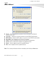
Without a valid certificate, users may encounter the following problem in IE8 when they try
to access WIAS-3200N v2 GUI (https://192.168.1.254). There will be a “Certificate Error”,
because the browser treats WIAS-3200N v2 as an illegal website.
27
AirLive WIAS-3200N v2 User’s Manual
3. Configure Hotspot to Network
Click “Continue to this website” to access the WIAS-3200N v2's GUI. The WIAS-3200N
v2's Home page will be appearing.
*Note: If you already have an SSL Certificate, please click UploadKey button to select the
file and upload it.
Enable Telnet: Select Enable Telnet to activate Telnet Service
Telnet Port: Please input 1 ~ 65535 value to set Telnet Port; default value is 23.
Enable SSH: Select Enable SSH to activate SSH Service
SSH Port: Please input 1 ~ 65535 value to set SSH Port; default value is 22.
*Note: Click GenerateKey button to generate RSA private key. The “Display the host key
footprint” gray blank will be show content of RSA key.
3.6.6
E-mail SMTP Relay
Select Enable Service to activate Email SMTP Relay function. Enter SMTP relay server in
IP Address/ Domain field.
AirLive WIAS-3200N v2 User’s Manual
28
3 Configure Hotspot to Network
3.6.7
Ping Watchdog
The ping watchdog sets the WIAS-3200N v2 to continuously ping a user defined IP
address (it can be the Internet gateway for example). If it is unable to ping under the user
defined constraints, the WIAS-3200N v2 will automatically reboot. This option creates a
kind of "fail-proof" mechanism.
Ping Watchdog is dedicated for continuous monitoring of the particular connection to
remote host using the Ping tool. The Ping works by sending ICMP “echo request” packets
to the target host and listening for ICMP “echo response” replies. If the defined number of
replies is not received, the tool reboots the device.
Enable Ping Watchdog: control will enable Ping Watchdog Tool.
IP Address to Ping: specify an IP address of the target host which will be monitored
by Ping Watchdog Tool.
Ping Interval: specify time interval (in seconds) between the ICMP “echo requests”
are sent by the Ping Watchdog Tool. Default is 300 seconds.
Startup Delay: specify initial time delay (in seconds) until first ICMP “echo requests”
are sent by the Ping Watchdog Tool. The value of Startup Delay should be at least 60
seconds as the network interface and wireless connection initialization takes
considerable amount of time if the device is rebooted. Default is 300 seconds.
Failure Count To Reboot: specify the number of ICMP “echo response” replies. If the
specified number of ICMP “echo response” packets is not received continuously, the
Ping Watchdog Tool will reboot the device.
Change these settings as described here and click Save button to save your changes.
Click Reboot button to activate your changes
29
AirLive WIAS-3200N v2 User’s Manual
3. Configure Hotspot to Network
3.7 Time Server
System time can be configured via this page where manual setting and NTP server
configuration are both supported. Please click on System > Time Server and follow the
below setting.
3.7.1
System Time
Display the current time of the system.
3.7.2
Setup Time Use NTP
To enable Network Time Protocol, NTP, to synchronize the system time with NTP server.
Default NTP Server: Select the NTP Server from the drop-down list.
Time Zone: Please set a time zone from where the accurate time can be supplied,
(GMT+08:00) Taipei for example.
Daylight saving time: Enable Daylight saving time from where the accurate time
needed.
*Note: If Time server setting selected in “Setup Time User NTP”, please verify system's
Default Gateway and DNS setting first.
AirLive WIAS-3200N v2 User’s Manual
30
3 Configure Hotspot to Network
3.7.3
User Setup
Administrator can set Time manually. Click Set Time button and Save button to change
Local Time.
3.7.4
Time Display Format
Administrator can set system's time format. Enter a desired time format or use the default
provided.
Change these settings as described here and click Save button to save your changes.
Click Reboot button to activate your changes
31
AirLive WIAS-3200N v2 User’s Manual
3. Configure Hotspot to Network
3.8 SNMP
SNMP is an application-layer protocol that provides a message of format for
communication between SNMP managers and agents. By enabling SNMP function, the
administrator can obtain the system information remotely. Please click on System > SNMP
Setup and follow the below setting.
3.8.1
SNMP v2c
Enable: Check to enable SNMP v2c.
ro community : Set a community string to authorize read-only access.
rw community : Set a community string to authorize read/write access.
3.8.2
SNMP v3
Enable: Check to enable SNMP v3. SNMPv3 supports the highest level SNMP
security.
SNMP ro user: Set a community string to authorize read-only access.
SNMP ro password: Set a password to authorize read-only access.
SNMP rw user: Set a community string to authorize read/write access.
SNMP rw password: Set a password to authorize read/write access.
3.8.3
SNMP Trap
Events such as cold start, interface up & down, and association & disassociation will report
to an assigned server.
Enable: Check to enable SNMP Trap.
Community: Set a community string required by the remote host computer that will
receive trap messages or notices sends by the system.
IP: Enter the IP addresses of the remote hosts to receive trap messages.
Change these settings as described here and click Save button to save your changes.
Click Reboot button to activate your changes
AirLive WIAS-3200N v2 User’s Manual
32
4 Configure Service Domain
4
4. Configure Service Domain
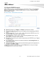
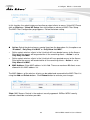
4.1 Service Domain
WIAS-3200N v2 support 4 Service Domain, administrator can quick setup hotspot via this
page. Each VAP can move to different Domain.
: Click tools icon on the top-right corner of each Domain settings window, the
Service Domain page will pop-up.
LAN/VLAN : The bonding interface for this Service Domain
Auth Type: The authentication type for this Service Domain. There are four types:
Pregenereated Ticket, On-demand, Local Users and Remote RADIUS Server.
IP PnP Service: Denote the current status of IP PnP service on the respective
Service Domain.
Guest Service: Denote the current status of guest service on the respective
Service Domain.
Time Policy: Denote the schedule of authentication service on the respective
Service Domain.
Redirect URL: Denote the redirect URL on this Login page of Service Domain.
Login Domain Name : Denote the login domain name on the respective Service
Domain
33
AirLive WIAS-3200N v2 User’s Manual
4 Configure Service Domain
Login Page: The custom page for this Service Domain. There are two types :
Template page or Upload page
: Click signal icon on each VAP field, the VAP Setup will pop-up.
4.1.1 Service Domain
Administrator can configure Service Domain with different authentication service type, IP
PnP service, guest free service, idle time , redirect URL, scheduling authentication service
and customization login page.
Click on Service Domain > Tools icon or Service Domain > Service Domain# to enter
Service Domain Setup page.
Authentication Options: Select authentication type for this Service Domain. The
system supports multiple authentications in one Service Domain.
Auth Type: Select desired authentication type for this Service Domain, each Domain
supports multiple authentications.
Default Auth Type: Select default authentication type for this Service Domain.
Pregenerated Ticket: Select desired tickets database for Pregenerated
authentication after creating the database of Pregenerated Tickets.
Login Options: When authentication type selected in Auth Type, the Login Options
setting field will appear.
Login Timeout: Enter idle timeout for this Service Domain. If users have idled with
no network activities, the system will automatically logout the users. The Login
Timeout can be set between 0 to 1440 minutes, and the default timeout is 10 minutes.
Redirect URL: Enter the specified website to redirect, when users log in successfully,
the pop-up page will direct to the specified URL.
AirLive WIAS-3200N v2 User’s Manual
34
4 Configure Service Domain
Login Domain Name: Enter the specified URL to display login page. If you close the
login page and because you can’t click Logout button to stop service, you can enter
specified URL on browser to display login page.
Time Policy: Select desired scheduling of the respective Service Domain for
authentication service. Scheduling setting is on Time Policy page.
IP PnP Service: IP Plug and Play, the AC-920X supports IP PnP for the respective
Server Domain. At the user end, a static IP address can be used to connect the
system. Regardless of what the IP address at the user end is, authentication can still
be performed through WIAS-3200N v2.
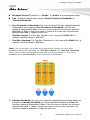
Guest Service: By default; it's “Disable”. To Enable to activate guest service
limitation, the Guest button will appear on the login portal window. Below depicts an
example Guest Service.
Guest Count Limit: Enter maximum number of guest to a desired number in the
range of 1-100. The default value is 5. For example, while the number of the guest is
set to 5, only 5 guests are allowed to connect to Internet via controller at the same
time.
Guest Time: Enter maximum free service time for guest user within 24 hours. The
default is 10 Minutes; the range is between 1 to 720 Minutes.
Expired
Login
Guest Time = 720 Minutes
Block
Free
6/17 00:00
6/17 12:00
6/18 00:00
Custom Pages: Configure Custom pages for this Service Domain. Administrator can
select Template Page or Upload Customize Page.
Template Page: Choose Template Page to make a customized login page. Click
select to pick up a color and then fill in all of the banks. You also can use Color
Template for your template. If you use Color Template, please click Apply button to
change all color. You can change the text as your wish. After finishing the setting, Click
Save button and Preview button to see the result.
35
AirLive WIAS-3200N v2 User’s Manual
4 Configure Service Domain
Upload Page: Choose the Upload Page selection and click Upload button to upload
the designated page and photo. The upload files will be listed on the File List field.
Below depicts an example for upload File List. The file name of upload page must be
“login.html”
Change these settings as described here and click Save button to save your changes.
Click Reboot button to activate your changes
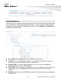
* Example for Upload Page:
Here the codes are supplied. Please note that the red part is for the login feature (can't not
modified), the green part can be modified freely by administrators.
<meta name="apple-mobile-web-app-capable" content="yes" /><!--Auto Login for Mac-->
<meta names="apple-mobile-web-app-status-bar-style" content="black" /><!--Auto Login
for Mac-->
<html>
<head>
<title><?hHotspot_main_title></title>
<?JAVASCRIPT>
</head>
<body>
<h1><?hHotspot_main_title></h1>
<p><?hHotspot_sub_title><p>
<div id="CW_MSG"></div><!--Main Login Form Content-->
<div id="CW_INFO"><span id="CW_HELP"></span></div><!--Main Help Content-->
<div id="WALLED"></div><!-- Walled Garden-->
<?hHotspot_footer_title>
</body>
</html>
AirLive WIAS-3200N v2 User’s Manual
36
4 Configure Service Domain
If login page need insert images or css file, please include path “/upload/vlan0/” ~
“/upload/vlan7/”, the “vlan0” ~”vlan7” indicate “Service Domain0” ~ “Server Domain7”,
below depicts an example for insert image001.gif image file to login page of Service
Domain0.
<img src="/upload/vlan0/image001.gif">
Below depicts an example for <div id="WALLED"></div> content
<div class="ad"><a href="http://www.google.com" title=""
target="_blank">Google</a></div>
You only can modify <div class="ad">, here is define CSS content for <div class="ad">
.ad{
float: left;
display: inline=block;
text-align: center;
width: 100px;
margin: 5px;
padding: 5px;
background: #fff;
font-size: 14px;
font-weight: bold;
}
.ad a{
text-decoration: none;
color: red;
}
.ad:hover, .ad a:hover, ad a:active{
background: #333333;
color: blue;
}
4.2 Authentication
WIAS-3200N v2 support 5 types of authentication: Pregenerated Tickets, On-Demand
Users, Local RADIUS Accounts, Remote RADIUS Server and Remote LDAP Server. This
section depicts to configure the settings for Pregenerated tickets, On-Demand users and
authentication server. If authentication selected in None, the clients can access Internet
without authentication.
4.2.1 Authentication Management
The WIAS-3200N v2 supports multiple login for one accounts and administrator can
configure alias name of the respective authentication type on login page. Please click on
Service Domain → Authentication → Authentication Management, and follow the
below setting.
37
AirLive WIAS-3200N v2 User’s Manual
4 Configure Service Domain
Multiple Login: Select Enable to activate multiple login service, and Disable to
inactivate multiple login service.
Auth Type: Denote authentication type of the system.
Service Name: Enter desired alias name of the respective authentication type on
login page.
Description: Enter desired description name of the respective authentication type.
Change these settings as described here and click Save button to save your changes.
Click Reboot button to activate your changes.
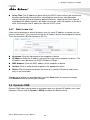
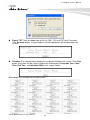
4.2.2 Pregenerate Ticket
This section is for administrators to Pregenerated authentication tickets for entire external
Network. There are three types of time policy ticket can be generated (One Time, Multiple
Times, Volume and Unlimited Until End Time). Please click on Service Domain >
Authentication > Pregenerated Tickets, and follow the below setting.
AirLive WIAS-3200N v2 User’s Manual
38
4 Configure Service Domain
Ticket Setting
File ID: Enter the 8 hex digit numbers for identifying tickets database, this setting is
optional, If you don't specified file ID, the system will automatically generate. (The
range is 1-32767; Auto generated if no setting.)
Price: The price charged for this tickets database.
Currency : Select currency from drop-down list or enter customize currency for this
tickets database
Quantity of Tickets: The range is 1-3066. To specify desired quantity of tickets for
this database
Passcode Type: There are different passcode types for this tickets database: All Digit,
All Letters, and Mix Digit Letter. Select All Letters or Mix Digit Letter, the sub-item
should be shown-up. Select desired excluding letters for passcode of ticket database.
Passcode Length : Specify desired passcode length between 8 to 32 for this tickets
database
39
AirLive WIAS-3200N v2 User’s Manual
4 Configure Service Domain
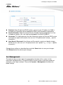
Wireless Information : Specify desired wireless information for this tickets
database(Up to 512 characters)
Description : Enter appropriate text to denote this database
Billing Type
Type: There are different billing policies for this tickets database: One Time, Multiple
Times, Volume and Unlimited Until End Time. Select One Time or Multiple Times or
Volume, the Quota sub-item should be shown-up.
Quota : Enter the time quota for One Time and Multiple Times policy (the maximum
volume allowed is 527040 (366day * 24 * 60)minutes, default is 60 minutes); or enter
the volume quota for Volume policy ( the maximum volume allowed is 102400 MB,
default is 10 MB)
Effective Starting Time : Specify desired effective starting time for this tickets
database
Effective Ending Time : Specify desired effective ending time for this tickets
database
Click Save button to create database of ticket.
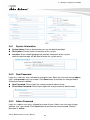
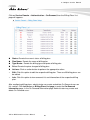
Pregenerated Tickets Database List
Shows all created ticket of database in the list
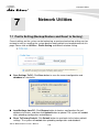
Import Tickets File: Click this to upload the tickets of database. Click “Select File”
button to select the file for the tickets upload. The “Upload File ...” message will appear.
(The format is “*.bin”)
AirLive WIAS-3200N v2 User’s Manual
40
4 Configure Service Domain
File ID: Denote the identity number of the database.
Price: Denote the price of ticket in the database.
Quantity:
Description : Denote the additional information of database
Actions: Click an action button to perform the appropriate action.
Info: Click this option to view information of each tickets database.
41
AirLive WIAS-3200N v2 User’s Manual
4 Configure Service Domain
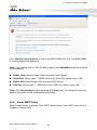
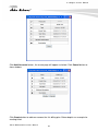
Below depicts an example for information of Pregenerated tickets databases when you
click”Info“option
Edit: Click this option to edit Wireless Information and Description in selected tickets
database.
Delete: Click this option to delete selected tickets database.
Ticket Information
Show the ticket information in this database.
AirLive WIAS-3200N v2 User’s Manual
42
4 Configure Service Domain
File ID : Denote the identity number of the database
Wireless Information : Denote the wireless information on the ticket
Description : Denote additional information on the ticket
Effective Starting Time : Denote the effective starting time on the ticket
Effective Ending Time : Denote the effective ending time on the ticket
Type and Quota : Denote the billing type and service quota on the ticket
Passcode Type : Denote the passcode type on the ticket
Passcode Length : Denote the passcode length on the ticket
Quantity : Denote the quantity of ticket in this database
Price : Denote the price charged on the ticket
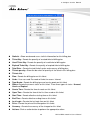
Statistic : Show the statistics of information in this database
Ticket Qty : Denote the quantity of created ticket in this database
Used Ticket Qty : Denote the quantity of used ticket in this database
Expired Ticket Qty : Denote the quantity of expired ticket in this database
Total Price : Denote the total ticket's price and currency in this database
Export Tickets
There are three methods to backup your information of ticket databases
Export BIN: The administrator can backup ticket database or copy to other AC-920X.
Click Export button, the ticket databases (FileID_passcode.bin) will be download
from system. Below depicts an example for exporting tickets database.
43
AirLive WIAS-3200N v2 User’s Manual
4 Configure Service Domain
Export TXT: There are three type of file list: XML, CSV and TXT(only Passcode).
Click Generate button, the passcode list of ticket databases will be download from
system.
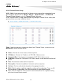
Printable: The selected ticket databases can be previewed on the screen. Click Print
button, the tickets will be shown including the information of Passcode, Price, Start
Time, End Time, and Available SSID on the screen. Admin
Below depicts an example for printable tickets
AirLive WIAS-3200N v2 User’s Manual
44
4 Configure Service Domain
Show all tickets in this database
Tickets List :
File ID : Denote the identity number of the database
Code : User can used Passcode of ticket for access Internet
Type/Quota : Denote the billing type and service quota on this ticket
Status: Denote the status of ticket. There three types of status : Unused, Used and
Expired
Create Time : Denote the ticket create time
Open Time : Denote the time of the first time used on this ticket
Start Time : Denote effective starting time on this ticket
End Time : Denote effective ending time on this ticket
Last Login : Denote the last login time on this ticket
Price: Denote the price of the charged on this ticket.
Currency : Denote the currency of the charged on this ticket
Actions: Click an action button to perform the appropriate action.
Delete: Click this option to remove ticket from this billing plan. When administrator
clicks this option, the alert message will appear as below.
Click Refresh button to reload the page.
*Note: After you login system via Pregenerated authentication, the timer page will appear.
Don't close Timer page (Because the Logout button on this page)
If Timer Page doesn't appear in the browser, please enter “http(s)://domain0.login” to open
Timer Page
4.2.3 On-Demand
Administrators can enable and configure this authentication method to provide clients
access in a Hotspot environment. Major functions include billing plans creation, accounts
creation, accounts monitoring list, thermal printer support, billing report statistics, and
external payment gateway support. There are three method to generate On-Demand
accounts: Generate by Manual, Print from Thermal Printer, Generate after Online
Payments.
45
AirLive WIAS-3200N v2 User’s Manual
4 Configure Service Domain
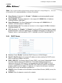
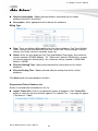
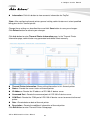
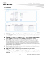
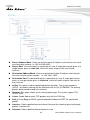
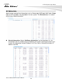
Click on Service Domain > Authentication > On-Demand, then the Billing Plans List
page will appears.
Status: Denote the current status of billing plan.
Plan Name: Denote the name of billing plan
Type/Quota : Denote the billing type and quota of billing plan
Price: Denote the price charged of billing plan
Actions: Click an action button to perform the appropriate action.
Edit: Click this option to edit the respective billing plan. There are 10 billing plans can
be edited.
Info: Click this option to view accounts list and information of the respective billing
plan.
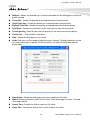
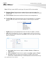
After configuring billing plans, administrator can create and delete On-Demand users on
this section. Click Info button on Billing Plans List page to enter the On-Demand
Information page. In the On-Demand Information page. Administrator may create and
delete On-Demand users.
AirLive WIAS-3200N v2 User’s Manual
46
4 Configure Service Domain
Plan Information : Show plan information in this billing plan
Service : Denote the current status of billing plan
Plan Name : Denote the plan name of billing plan
Price : Denote the price charged of billing plan
Wireless Information : Denote the wireless information of billing plan
Description :
Type and Quota : Denote billing type and service quota of billing plan
Effective Starting Time : Denote effective starting time of billing plan
Effective Ending Time : Denote effective ending time of billing plan
Denote additional information of billing plan
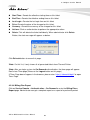
Click Preview button to preview ticket in the billing plan. Below depicts an example for
previewing ticket. Click Close button to close window.
47
AirLive WIAS-3200N v2 User’s Manual
4 Configure Service Domain
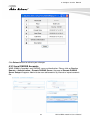
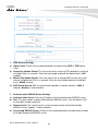
Click Add Accounts button, the create page will appear as below. Click Cancel button to
close window.
Click Create button to add new account for this billing plan. Below depicts an example for
creating ticket.
AirLive WIAS-3200N v2 User’s Manual
48
4 Configure Service Domain
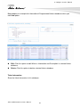
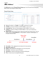
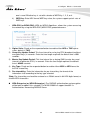
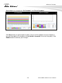
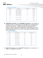
Statistic : Show on-demand users statistic information for this billing plan
Ticket Qty : Denote the quantity of created ticket of billing plan
Used Ticket Qty : Denote the quantity of used ticket of billing plan
Expired Ticket Qty : Denote the quantity of expired ticket of billing plan
Total Price : Denote the total ticket's price and currency of billing plan
Tickets per day : Show the bar chart of quantity of the ticket in this billing plan
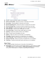
Tickets List :
Plan : Denote the billing plan on this ticket
Code : User can used Passcode of ticket for access Internet
Type/Quota : Denote the billing type and service quota on this ticket
Status: Denote the current status on this ticket. There three types of status : Unused,
Used and Expired
Create Time : Denote the time of create on this ticket
Open Time : Denote the time of the first time used on this ticket
Start Time : Denote effective starting time on this ticket
End Time : Denote effective ending time on this ticket
Last Login : Denote the last login time on this ticket
Price : Denote the price of the charged on this ticket
Currency : Denote the currency of the charged on this ticket
Actions: Click an action button to perform the appropriate action.
49
AirLive WIAS-3200N v2 User’s Manual
4 Configure Service Domain
Delete: Click this option to remove ticket from this billing plan. When administrator
clicks this option, the alert message will appear as below.
Click Refresh button to renew this page.
*Note: The list only shows generate of the ticket by clicking Add Account button.
*Note: After you login system via On-Demand authentication, the timer page will appear.
Don't close Timer page (Because the Logout button on this page)
If Timer Page doesn't appear in the browser, please enter “http(s)://domain0.login ” to open
Timer Page.
4.2.3.1 Billing Plan Setup
Click on Service Domain > Authentication > On-Demand,and click Edit option on
Billing Plans List, the Billing Plan Setup page will appear.
AirLive WIAS-3200N v2 User’s Manual
50
4 Configure Service Domain
Billing Plan0 Setup
Service: By default, it's “Disable”. To “Enable” to activate this billing plan.
Plan Name: Enter plan name for this billing plan.
Price: The price charged and currency for this billing plan.
* Note: The Paypal payment gateway does not support “Customize Currency” option.
Passcode Type: There are different passcode types for this billing plan: All Digit, All
Letters, Mix Digit Letter. Select All Letters or Mix Digit Letter, the sub-item should be
shown-up. Select desired excluding letters for passcode of ticket databases.
Passcode Length: Specify desired passcode length between 8 to 32 for this billing
plan.
Wireless Information: Enter the wireless information for this billing plan.
Description: Enter any additional information that will appear at the bottom of the
receipt.
Paypal Description: Enter any additional information that will appear at the list of the
login page.
Receipt Header: Enter header information that will appear at the top of the receipt.
Receipt Footer: Enter footer information that will appear at the bottom of the receipt.
51
AirLive WIAS-3200N v2 User’s Manual
4 Configure Service Domain
Billing Type
Billing Type: There are different policies for this billing plan: One Time, Multiple
Times, Volume and Unlimited Until End Time. Select One Time or Multiple Times or
Volume, the Quota sub-item should be shown-up.
Quota : Enter the time quota for One Time and Multiple Times policy (the maximum
volume allowed is 527040 minutes, default is 60 minutes); or enter the volume quota
for Volume policy ( the maximum volume allowed is 102400 MB, default is 10 MB)
Effective Starting Time: Specify desired effective starting time for this billing plan.
Effective Ending Time: Specify desired effective ending time for this billing plan.
Display Item Option
Select desired display item for ticket
Change these settings as described here and click Save button to save your changes.
Click Reboot button to activate your changes.
AirLive WIAS-3200N v2 User’s Manual
52
4 Configure Service Domain
4.2.3.2 Payment Gateway
This section is for merchants to set up an external payment gateway to accept payments in
order to provide access service to end customers who wish to pay for the service on-line.
Select Paypal to enable External Payment Gateway. Before setting up “PayPal”, it is
required that the merchant owners have a valid PayPal “API Username”, “API Password”.
Please see Appendix D – Accepting Payments via PayPal, Appendix E – Examples of
Making Payments for End Users for more information about setting up a PayPal
Business Account, relevant maintenance functions, and example for end users.
*Note: The Paypal payment gateway does not support “Customize Currency” option on
Billing Plan.
After opening a PayPal Business Account, the merchant should find the “API Signature” of
this PayPal account to continue “External Payment Gateway Setup”.
API Username: This is the “Login ID”(E-mail address) that is associated with the
PayPal Business Account.
API Password: This is the “Login Password” that is associated with the PayPal
Business Account.
53
AirLive WIAS-3200N v2 User’s Manual
4 Configure Service Domain
API Signature: This the key used by Paypal to validate all the transactions.
Invoice Number: An invoice number may be provided as additional information
against a transaction.
Current No. : Show current invoice number.
Billing Plan Setup List :
Enable: Select specified the billing plan for this payment gateway.
Plan Name : Denote the name of billing plan
Type/Quota : Denote the billing type and quota of
Price : Denote the price charged of billing plan
Information: Click this button to view accounts information for PayPal.
billing plan
Payment Gateway Information
Show current ticket's invoice number.
Click Edit button to enter Payment Gateway Setup page.
Statistic : Shows on-demand users statistic information for this billing plan via
payment gateway created
Ticket Qty : Denote quantity of created ticket from payment gateway
Used Ticket Qty : Denote quantity of used ticket from payment gateway
Expired Ticket Qty : Denote quantity of expired ticket from payment gateway
Total Price : Denote total ticket's price and currency from payment gateway
Tickets per day : Show the bar chart of quantity of the ticket from payment gateway
AirLive WIAS-3200N v2 User’s Manual
54
4 Configure Service Domain
Show tickets information
Tickets List :
Plan : Denote the billing plan on this ticket
Code : User can used Passcode of ticket for access Internet
Type/Quota : Denote the billing type and service quota on this ticket
Status: Denote the current status on this ticket. There three types of status : Unused,
Used and Expired
Create Time : Denote the time of create on this ticket
Open Time: Denote the time of the first time used on this ticket
Start Time : Denote effective starting time on this ticket
End Time : Denote effective ending time on this ticket
Last Login : Denote the last login time on this ticket
Price: Denote the price of the charged on this ticket.
Currency : Denote the currency of the charged on this ticket
Actions: Click an action button to perform the appropriate action.
Delete: Click this option to remove ticket from this billing plan. When administrator
clicks this option, the alert message will appear as below.
Click Refresh button to renew this page.
*Note: On this List, it only shows all of generated tickets through External Payment
Gateway.
*Note: After you login system via On-Demand authentication, the timer page will appear.
Don't close Timer page (Because the Logout button on this page)
If Timer Page doesn't appear in the browser, please enter “http(s)://domain0.login” to open
Timer Page.
*Note: If administrator wants to refund transaction, please see Appendix E. Issue
Refund for PayPal
55
AirLive WIAS-3200N v2 User’s Manual
4 Configure Service Domain
4.2.3.3 Thermal Printer Setup
WIAS-3200N v2 can generate ticket of On-Demand users manually or automatically from
Thermal Printer. Please click on Service Domain → Authentication → On-Demand →
Thermal Printer Setup to enter the Thermal Printer List page.
In the Thermal Printer List page, administrator may configure Thermal Printer setting and
generate tickets manually and delete tickets.
*Note: If administrator wants to generate tickets from Thermal Printer, system must use
DS-100 v2 to control Thermal Printer.
Status : Denote the current status of thermal printer
IP Address : Denote the IP address of f DS-100 v2 device server
Command Port : Denote the command port of f DS-100 v2 device server
COM Port : Denote the COM port of f DS-100 v2 device server to connect to thermal
printer
Date : Denote balance date of thermal printer
Description : Denote the additional information of thermal printer
Actions: Click an action button to perform the appropriate action.
Edit: Click this option to edit the respective settings of thermal printer. There are 10
thermal printer can be edited. Each thermal printer can specified billing plan
Info : Click this option to view accounts list and information of the respective billing
plan from thermal printer created
AirLive WIAS-3200N v2 User’s Manual
56
4 Configure Service Domain
Click Edit button to enter Thermal Printer Setup page. In the Thermal Printer Setup page,
administrator may configure related settings.
Thermal Printer Setup
Service: By default, it's “Disable”. To “Enable” to activate this function.
IP Address : Enter the IP address of WIAS-3200N v2 serial server
Command Port : Enter the command port of WIAS-3200N v2 serial server
COM Port : Select the COM port of WIAS-3200N v2 serial server to connect to
thermal printer
Balance Date: Enter balance date for statement printing from thermal printer. Thermal
printer can print “Current Balance” or “Early Balance” statement. Below depicts an
example for balance date.
Balance Date
6/17 23:59
Early Balance
6/17 00:00
Current Date
Current Balance
6/17 23:59 6/18 00:00
Description : Enter appropriate text to denote this thermal printer
Billing Plan Setup List :
Enable : Select specified the billing plan for this thermal printer
Plan Name : Denote the name of billing plan
Type/Quota : Denote the billing type and quota of billing plan
Price : Denote the price charged of billing plan
57
6/18 20:00
AirLive WIAS-3200N v2 User’s Manual
4 Configure Service Domain
Information: Click this button to view accounts information for PayPal.
*Note: After configuring thermal printer general setting, administrator must select specified
billing plan for this thermal printer.
Change these settings as described here and click Save button to save your changes.
Click Reboot button to activate your changes
Click Info button to enter Thermal Printer Information page. In the Thermal Printer
Information page, administrator may generated and delete ticket manually.
Thermal Printer Information: Show setting information in this thermal printer.
Status : Denote the current status of thermal printer
IP Address : Denote the IP address of DS-100 v2 device server
Command Port : Denote the command port of f DS-100 v2 device server
COM Port : Denote the COM port of f DS-100 v2 device server to connect to thermal
printer
Date : Denote balance date of thermal printer
Description : Denote the additional information of thermal printer
Click Edit button to enter Thermal Printer Setup page.
AirLive WIAS-3200N v2 User’s Manual
58
4 Configure Service Domain
Statistic : Shows on-demand users statistic information for this billing plan via thermal
printer created
Ticket Qty : Denote the quantity of created ticket from thermal printer
Used Ticket Qty : Denote the quantity of used ticket from thermal printer
Expired Ticket Qty : Denote the quantity of expired ticket from thermal printer
Total Price : Denote the total ticket's price and currency from thermal printer
Tickets per day : Show the bar chart of quantity of the ticket from thermal printer
Tickets List : Show tickets information
Plan : Denote the billing plan on this ticket
Code: User can use Passcode of ticket for access Internet. Clicking hyperlinks to view
this ticket information as below. Click Print button, the ticket will print from thermal
printer again.
Type/Quota : Denote the billing type and service quota on this ticket
Status: Denote the current status on this ticket. There three types of status : Unused,
Used and Expired
Create Time : Denote the time of create on this ticket
Open Time : Denote the time of the first time used on this ticket
59
AirLive WIAS-3200N v2 User’s Manual
4 Configure Service Domain
Start Time : Denote the effective starting time on this ticket
End Time : Denote the effective ending time on this ticket
Last Login : Denote the last login time on this ticket
Price: Denote the price of the charged on this ticket.
Currency : Denote the currency of the charged on this ticket
Actions: Click an action button to perform the appropriate action.
Delete: This will delete the ticket individually. When administrator click Delete
Button, the alert message will appear as below.
Click Refresh button to renew this page.
*Note: On this List, it only shows all of generated tickets from Thermal Printer.
*Note: After you login system via On-Demand authentication, the timer page will appear.
Don't close Timer page (Because the Logout button on this page)
If Timer Page doesn't appear in the browser, please enter “http(s)://domain0.login” to open
Timer Page.
4.2.3.4 Billing Plan Report
Click on Service Domain > Authentication > On-Demand to enter the Billing Plans
Report page. Administrator can get a complete report or a report of a particular period.
AirLive WIAS-3200N v2 User’s Manual
60
4 Configure Service Domain
Search Create Time Range
On-Demand Type: There are four type can be selected: ALL, Manually Create,
Payment Gateway and Thermal Printer.
Start Time : Specify desired search starting time
End Time : Specify desired search ending time
Search Result: Select a time period to get a period report. The report tells the total
income and individual accounting of each plan for all plans available for that period of
time.
.
Search Result
Shows search result of the specified time range
61
AirLive WIAS-3200N v2 User’s Manual
4 Configure Service Domain
Search Time: Denote the specified search time range.
Name: Denote the name of billing plan.
On-Demand: Denote the quantity of ticket from manually created.
Payment Gateway: Denote the quantity of ticket from payment gateway created.
Thermal Printer: Denote the quantity of ticket from thermal printer created.
Amount Qty: Denote total quantity of created ticket of billing plan.
Unit Price: Denote the unit price of billing plan.
Subtotal: Denote the total price of billing plan.
Total: Denote the total price and quantity on all billing plan.
4.2.3.5 Ticket Customization
Click on Service Domain > Authentication > On-Demand to enter the Ticket
Customization page. Administrator can edit text on printed ticket on this page.
Change these settings as described here and click Save button to save your changes.
Click Preview button to preview ticket in the Billing Plan 0. Below depicts an example for
previewing ticket. Click Close button to close window.
AirLive WIAS-3200N v2 User’s Manual
62
4 Configure Service Domain
Click Reboot button to activate your changes
4.3.3 Local RADIUS Accounts
WIAS-3200N v2 provide Local RADIUS server authentication. Please click on Service
Domain > Authentication > Remote RADIUS Server, the page of Remote RADIUS
Server Setup will appear. Administrator can add accounts by manual or import accounts
file.
63
AirLive WIAS-3200N v2 User’s Manual
4 Configure Service Domain
Group Setup: Enter the specified name on group and click Add button to create. Up
to 20 groups can add. (You can set 4-16 alphanumeric and ~!@#$%^*()_+-:{}
|:<>?[]/,’.= specific characters)
Group List: Display all of groups in the list, click Delete option to remove group name
and all of the accounts in this group will be removed, click Edit option to change group
name.
RADIUS Accounts Setup :
Username/Password: Enter the username and password of account on local
RADIUS authentication.(You can set 4-16 alphanumeric and ~!@#$%^*()_+-:
{}|:<>?[]/;’..= specific characters)
MAC Address:
Enter the MAC address of account on local RADIUS authentication.
(Optional)
Description: Enter appropriate text to denote this account.
Group: Select the specified group on local RADIUS authentication, default is None.
Click Save button to add new account, all of accounts can be edited (Username cannot
edit) and deleted.
Local RADIUS Accounts List
Delete: Select the specified group and click Delete button to remove accounts of the
specified group.
AirLive WIAS-3200N v2 User’s Manual
64
4 Configure Service Domain
Import Accounts File: Select the specified group on Group option and click Select
File button to select the text file for uploading the accounts of the specified group. The
the “Upload File ...” message will appear.
The upload file should be a text file and the format of each line is “Username, Password,
MAC, Description” without the quotes. There must be no spaces between the fields and
commas. The MAC field could be omitted but the trailing comma must be retained. When
adding accounts by uploading a file, the existing accounts in the embedded database,
uploading process will fail. Below depicts an example for text file.
*Note: The same Username account can't exist on different groups, the Group option only
for convenient management.
Export Accounts File: Select the specified group on Group option and click Export
button to save accounts of the specified group to PC. The “File Download” window will
appear.
65
AirLive WIAS-3200N v2 User’s Manual
4 Configure Service Domain
Search: Enter a keyword to be searched in the text field and all matching the
keyword will be listed.
Username :
MAC Address : Denote the MAC address of account on local RADIUS authentication
Description : Enter appropriate text to denote this account
Group : Denote the specified of account on local RADIUS authentication
Actions: Click an action button to perform the appropriate action.
Delete:
Edit : Click this option to edit the specified account
Denote the username of account on local RADIUS authentication
Click this option to remove the specified account.
*Note: These settings will become effective immediately after clicking the Save button.
AirLive WIAS-3200N v2 User’s Manual
66
4 Configure Service Domain
4.3.4 Remote RADIUS Accounts
WIAS-3200N v2 provide remote RADIUS server authentication. Please click on Service
Domain > Authentication > Remote RADIUS Server, the page of Remote RADIUS
Server Setup will appear
Service: By default, it's “Disable”. To “Enable” to activate this function.
Primary/Secondary Server IP: Enter the IP address of the Authentication RADIUS
server.
Authentication Port: The port number used by Authentication RADIUS server. Use
the default 1812 or enter port number specified.
Accounting Port: The port number used by Accounting RADIUS server. Use the
default 1813 or enter port number specified.
Secret Key: The secret key for system to communicate with RADIUS server. Support
1 to 64 characters.
Accounting Service: Select this to enable or disable the “Accounting Service” for
accounting capabilities.
Authentication Type: Select the desired authentication type from the drop-down list;
the options are CHAP and PAP.
Change these settings as described here and click Save button to save your changes.
Click Reboot button to activate your changes.
67
AirLive WIAS-3200N v2 User’s Manual
4 Configure Service Domain
4.3.5 Clear Tickets
Ticket Type: There are four ticket types for you to select: Pregenerated Ticket,
On-Demand Ticket, Payment Gateway, and Thermal Printer.
File ID: Select File ID.
Ticket Status: Select Expired or Use up.
Search: Click “Search” button to search the ticket which selected.
Delete: Click “Delete” button to delete the ticket which selected.
4.4 Privilege IP/MAC Address
This function provides local device can access Internet without authentication. If there are
some workstations belonging WIAS-3200N v2 that need to access to network without
authentication, enter the IP or MAC address of these workstations in this list. Up to 20
addresses can be defined in this list. Please click on Service Domain > Privilege IP/MAC
Address, the page of Privilege IP/MAC Address Setup will appear.
Privilege IP/MAC Address Setup
Device Name: Enter the name of the workstation, 4-32 characters.
AirLive WIAS-3200N v2 User’s Manual
68
4 Configure Service Domain
IP Address: Enter the IP address (or IP address/Mask) of the workstation. Permitting
specific IP addresses to have network access rights without going through standard
authentication process
MAC Address: Enter the MAC address of the workstation. Permitting specific MAC
addresses to have network access rights without going through standard
authentication process
Description: Enter appropriate text to denote this workstation, up to 64 characters.
Click Save button to add new rule, all of rules can be edited and deleted
Privilege IP/MAC Address List
Device Name: Denote the name of workstation.
IP Address : Denote the IP address(or IP address/Mask) of workstation
MAC Address: Denote the MAC address of workstation.
Description: Enter appropriate text to denote this workstation.
Actions: Click an action button to perform the appropriate action.
Delete :
Edit : Click this option to edit the specified item
Click this option to remove the specified item
4.5 Walled Garden
This function provides certain free services or advertisement web pages for users to
access the websites listed before login and authentication. Up to 20 address or domain
names of the websites can be defined in this list. User without the network access right can
still have a chance to experience the actual network service free of charge. Please click on
Service Domain > Walled Garden, the page of Walled Garden Setup will appear.
69
AirLive WIAS-3200N v2 User’s Manual
4 Configure Service Domain
Walled Garden
Name : Enter a descriptive name for this rule for identifying purposes
IP Address/Domain: Enter the IP address/Domain of the workstation.
Homepages: Enter the MAC address of the workstation.
Description : Enter appropriate text to denote this workstation
Click Save button to add new rule, all of rules can be edited and deleted
Walled Garden List
Name : Denote the name of workstation
IP Address/Domain : Denote the IP address(or IP address/Mask) of workstation
Actions: Click an action button to perform the appropriate action.
Delete :
Edit : Click this option to edit the specified item
Click this option to remove the specified item
After add website on the list, the Walled Name will appear on Login page.
an example for Walled Garden
AirLive WIAS-3200N v2 User’s Manual
70
Below depicts
4 Configure Service Domain
4.6 Blacklist
The administrator can add, delete and edit blacklist for uses access. If the system wants to
deny uses access to specified website, enter the IP address, URL or Keyword of these
websites in this list. Up to 20 rules can be defined in this list. Please click on Service
Domain → Blacklist, the page of Blacklist Setup will appear.
Blacklist Setup
Name : Enter a descriptive name for this rule for identifying purposes
IP Address/URL: Enter the specified IP address/URL of the website or Keyword of the
website. Rejecting specific website to access rights
Description: Enter appropriate text to denote this website.
Click Save button to add new rule, all of rules can be edited and deleted
71
AirLive WIAS-3200N v2 User’s Manual
4 Configure Service Domain
Blacklist
Name: Denote the name of rule
URL: Denote the IP address/URL or Keyword of the website
Actions: Click an action button to perform the appropriate action.
Delete:
Edit: Click this option to edit the specified item
Click this option to remove the specified item
4.7 Notification
WIAS-3200N v2 can automatically send the notification of Traffic Log, On-Demand Log,
Session Log and Billing Report to 3 particular E-mail addresses. A trial email is provided
by the system for validation. Please click on Service Domain > Notification, the page of
Notification E-mail Setup will appear.
SMTP Server Setup
AirLive WIAS-3200N v2 User’s Manual
72
4 Configure Service Domain
Enabled: Click Enabled to activated SMTP Server
Sender From: The E-mail address of the administrator in charge of monitoring. This
will show up as the sender's E-mail.
SMTP Server: The IP address / Domain of the sender's SMTP server.
Port: The port of the sender's SMTP server. (Default is 25)
*Note: Sometimes SMTP server use Port 587 for TLS encryption and Port 465 for SSL
encryption
Encryption: Some SMTP server needs encryption linking for sending E-mail. The
system provides encryption for sender's SMTP server
SMTP Auth: Some SMTP server needs authentication username and password for
sending E-mail. The system provides authentication for sender's SMTP server
Username: The sender's authentication username for STMP server
Password: The sender's authentication password for STMP server
Notification E-mail Setup
Receiver E-mail Address (es): Up to 3 E-mail address can be set up to receive the
notification. These are the receiver's E-mail address.
Sending Interval: The time interval (in minute) to send the E-mail report. (Default is
1440 minutes; the range is between 10 to 4200 minutes)
Billing Report Time: The start time of sending e-mail. For example: the Billing Report
Time is 14:00 and Sending Interval is 6 hours, the system will send report on 20:00.
SMTP Sending Test: Click Send button to verify Notification E-mail settings.
depicts an example for success sending test.
73
Below
AirLive WIAS-3200N v2 User’s Manual
4 Configure Service Domain
Syslog Setup
There are 3 types of Syslog supported: Syslog Log, On-Demand User Log and Session
Log. Enter the specify IP address and Port number to sent report.
*Note: The all history log are saved in the DRAM, if you restart system, the all of history log
will empty.
Change these settings as described here and click Save button to save your changes.
Click Reboot button to activate your changes.
If the history E-mail has been entered above Notification settings, after Sending Interval,
the system will send History E-mail to receiver's E-mail address automatically.
AirLive WIAS-3200N v2 User’s Manual
74
4 Configure Service Domain
Traffic Log
As shown in the following figure, each line is traffic history record consisting of 10 fields :
Date, Auth Type, Status, Passcode/Username, IP, MAC, Packets In, Bytes In, Packets
Out and Bytes Out.
Date : Denote the current event's date and time
Auth Type: There will shows 6 types of authentication: Pregenerated, On-Demand,
Local Users (Local RADIUS Users), Remote RADIUS, LDAP and Guest.
Status : There will show 10 types of status as below :
LOGIN : Denote the user login to the hotspot service
LOGOUT : Denote the user logout to the hotspot service
IDLE TIMEOUT : Denote the user idle time is over timeout setting of Service Domain,
the system will logout user automatically
USE UP : Denote the quota of time of user is over
SESSION TIMEOUT : Denote the user session timeout for connecting to remote
RAIDUS
VOLUME USE UP : Denote the quota of volume of user is over
KICK: Denote the system kick out the user.
TIME OUT OF RANGE : Denote the service time out of range
Passcode/Username : Denote the user's passcode or username
IP : Denote the user's IP address
MAC : Denote the user's MAC address
Packets In : Denote the current user's packets in
Bytes In : Denote the current user's bytes in
Packet Out : Denote the current user's packets out
Bytes Out : Denote the current user's bytes out
On-Demand Log
As shown in the following figure, each line is traffic history record consisting of 15 fields :
Date, Location, Status, Passcode/Username, IP, MAC, Packets In, Bytes In, Packets
Out, Bytes Out, Start Time, End Time, Plan, Payment Type and Cost
75
AirLive WIAS-3200N v2 User’s Manual
4 Configure Service Domain
Date : Denote the current event's date and time
Location : Denote the current device's location
Status : There will show 10 types of status as below :
LOGIN : Denote the user login to the hotspot service
LOGOUT : Denote the user logout to the hotspot service
IDLE TIMEOUT : Denote the user idle time is over timeout setting of Service Domain,
the system will logout user automatically
USE UP : Denote the quota of time of user is over
VOLUME USE UP : Denote the quota of volume of user is over
KICK : Denote the system kick out the user
TIME OUT OF RANGE : Denote the service time out of range
ADD OD ACCOUNT : Denote the system add On-Demand user account
DELETE OD ACCOUNT : Denote the system delete On-Demand user account
Passcode/Username : Denote the user's passcode or username
IP : Denote the user's IP address
MAC : Denote the user's MAC address
Packets In : Denote the current user's packets in
Bytes In : Denote the current user's bytes in
Packet Out : Denote the current user's packets out
Bytes Out :
Start Time : Denote the start time on this users
End Time : Denote the end time on this users
Plan : Denote the current user's billing plan
Payment Type : Denote the current payment type, there were show Cash or PayPal
Cost : Denote the current service charge
Denote the current user's bytes out
AirLive WIAS-3200N v2 User’s Manual
76
4 Configure Service Domain
Session Log: The system can recorded connection details of each user accessing
the Internet and sent out to a specified Syslog Server or E-Mail based on defined
interval time. As shown in the following figure, each line is traffic history record
consisting of 10 fields, Date, Time, Session Type, Username, Service Domain,
Source IP, Source Port, Destination IP, Destination Port, and MAC.
Billing Report
The system can record the billing report and sent out to a specified E-Mail based on
defined Billing Report Time. As shown in the following figure.
4.8 Online Users
The administrator can view status of all online users on each Service Domain. Please click
on Service Domain > Online Users, the page of Online Users will appear. Below depicts
an example for Online User Information. There provided information of Passocde, IP
Address, MAC Address, Login Time, Packets In/Out and Bytes In/Out.
Auth Type : Denote the current user's authentication type
Passcode/Username : Denote the current user's passcode or username
IP Address : Denote the current user's IP address
77
AirLive WIAS-3200N v2 User’s Manual
4 Configure Service Domain
MAC Address : Denote the current user's MAC address
Login Time : Denote the login time on this user
Packets In/Out : Denote the current user's packets in and out
Bytes In/Out : Denote the current user's bytes in and out
Actions: Click Logout option to logout online users
Click Refresh button to reload the page
4.9 Log Info
The WIAS-3200N v2 can record authentication traffic history and the system will
automatically send out the history information via notification service (See Notification
page). The history of each day will be saved separately in the DRAM for 3 days and sorted
by time, the traffic provides all login and logout activity of specific date. Other information
includes Passocde/Username, IP Address, MAC Address, Packets In/Out and Bytes In/Out.
Please click on Service Domain > Traffic Info, the page of Log Info will appear.
*Note: The all history log are saved in the DRAM, if you need restart system and also keep
the history, please manually copy and save the information before restarting.
Traffic Log
As shown in the following figure, each line is traffic history record consisting of 10 fields :
Date, Auth Type, Status, Passcode/Username, IP, MAC, Packets In, Bytes In, Packets
Out and Bytes Out.
Date : Denote current event's date and time
AirLive WIAS-3200N v2 User’s Manual
78
4 Configure Service Domain
Auth Type: There will shows 6 types of authentication: Pregenerated, On-Demand,
Local Users (Local RADIUS Users), Remote RADIUS, LDAP and Guest.
Status : There will show 10 types of status as below :
Passcode/Username: Denote the user's passcode or username.
IP : Denote the user's IP address
MAC : Denote the user's MAC address
Packets In: Denote the current user's packets in.
Bytes In:
Packet Out:
Bytes Out:
Denote the current user's bytes in.
Denote the current user's packets out.
Denote the current user's bytes out.
On-Demand Log
As shown in the following figure, each line is traffic history record consisting of 14 fields :
Date, Status, Passcode/Username, IP, MAC, Packets In/Out, Bytes In/Out, Start Time,
End Time, Plan, Payment Type and Cost.
Date : Denote current event's date and time
Status : There will show 10 types of status as below :
Passcode/Username: Denote the user's passcode or username.
IP : Denote the user's IP address
MAC : Denote the user's MAC address
Packets In: Denote the current user's packets in.
Bytes In:
Packet Out:
Bytes Out:
Start Time : Denote the start time of current service users
End Time : Denote the end time of current service users
Plan: Denote the current user's billing plan.
Payment Type : Denote the current payment type, there were show Cash or PayPal
Cost : Denote the current service charge
Denote the current user's bytes in.
Denote the current user's packets out.
Denote the current user's bytes out.
Click Refresh button to reload the page.
79
AirLive WIAS-3200N v2 User’s Manual
5 Configure Wireless Connection
5
5. Configure Wireless
Connection
5.1 General Setups
The administrator can change the data transmission, channel and output power settings for
the system. Please click on Wireless > General Setup and follow the below setting.
MAC address: The MAC address of the Wireless interface is displayed here.
Band Mode: Select an appropriate wireless band; bands available are 801.11b,
802.11b/g, 802.11b/g/n and 802.11n.
Transmit Rate Control: Select the desired rate from the drop-down list; the options
are auto or ranging from 1Mbps to 54Mbps for 802.11b/g modes, or 1Mbps to 11Mbps
for 802.11b mode.
Country: Select the desired country code from the drop-down list; the options are US,
ETSI and Japan.
Channel: The channel range will be changed by selecting different country code. The
channel range from 1 to 11 for US country code, or 1 to 13 for ETSI country code, or 1
to 14 for Japan (Channel 14 only for 802.11b Rate).
Auto Scan: Click this button, the channel will be changed to suitable channel.
AP List: Click this button, the system will show current all AP list. Click Rescan button
to rescan list, click Close button to close window
AirLive WIAS-3200N v2 User’s Manual
80
5 Configure Wireless Connection
Tx Power: You can adjust the output power of the system to get the appropriate
coverage for your wireless network. Select LEVEL 1 to LEVEL 7 needed for your
environment. If you are not sure of which setting to choose, then keep the default
setting, LEVEL 7.
When Band Mode select in 802.11b/g/n or 802.11n, the HT Physical Mode settings
should be show immediately.
Tx/Rx Stream: By default, it's 2.
Channel Bandwidth: The "20/40” MHz option is usually best. The other option is
available for special circumstances.
Extension Channel: Only for Channel Bandwidth “40” MHz Select the desired
channel bonding for control.
81
AirLive WIAS-3200N v2 User’s Manual
5 Configure Wireless Connection
MCS: This parameter represents transmission rate. By default (Auto) the fastest
possible transmission rate will be selected. You have the option of selecting the speed
if necessary.
Shout GI: Short Guard Interval, by default, it's “Enable”. It can increase throughput.
However, it can also increase error rate in some installations, due to increased
sensitivity to radio-frequency reflections. Select the option that works best for your
installation.
Aggregation: By default, it's “Enable”. To “Disable” to deactivated Aggregation. A part
of the 802.11n standard (or draft-standard). It allows sending multiple frames per
single access to the medium by combining frames together into one larger frame. It
creates the larger frame by combining smaller frames with the same physical source
and destination end points and traffic class (i.e. QoS) into one large frame with a
common MAC header.
Aggregation Frames: The Aggregation Frames is in the range of 2~64, default is 32.
It determines the number of frames combined on the new larger frame.
Aggregation Size: The Aggregation Size is in the range of 1024~65535, default is
50000. It determines the size (in Bytes) of the larger frame.
Change these settings as described here and click Save button to save your changes.
Click Reboot button to activate your changes. The item in this page is for AP's RF general
settings and will be applied to all VAPs and WDS Link.
5.2 Advanced Setup
The administrator can change the Slot Time, ACK Timeout, and RTS threshold and
fragmentation threshold settings for the system. Please click on Wireless > Advanced
Setup and follow the below setting.
AirLive WIAS-3200N v2 User’s Manual
82
5 Configure Wireless Connection
Slot Time: Slot time is in the range of 9~1489 and set in unit of microsecond. The
default value is 9 microsecond. Slot time is the amount of time a device waits after a
collision before retransmitting a packet. Reducing the slot time decreases the overall
back-off, which increases throughput. Back-off, which is a multiple of the slot time, is
the random length of time a station waits before sending a packet on the LAN. For a
sender and receiver own right of the channel the shorter slot time help manage shorter
wait time to re-transmit from collision because of hidden wireless clients or other
causes. When collision sources can be removed sooner and other senders attempting
to send are listening the channel (CSMA/CA) the owner of the channel should
continue ownership and finish their transmission and release the channel. Then,
following ownership of the channel will be sooner for the new pair due to shorter slot
time. However, when long duration of existing collision sources and shorter slot time
exist the owners might experience subsequent collisions. When adjustment to longer
slot time can’t improve performance then RTS/CTS could supplement and help
improve performance.
ACK Timeout: ACK timeout is in the range of 1~372 and set in unit of microsecond.
The default value is 64 microsecond. All data transmission in 802.11b/g request an
“Acknowledgement” (ACK) send by receiving radio. The transmitter will resend the
original packet if correspondent ACK failed to arrive within specific time interval, also
refer to as “ACK Timeout”.
ACK Timeout is adjustable due to the fact that distance between two radio links may
vary in different deployment. ACK Timeout makes significant influence in performance
of long distance radio link. If ACK Timeout is set too short, transmitter will start to
“Resend” packet before ACK is received, and throughput become low due to
excessively high re-transmission.
ACK Timeout is best determined by distance between the radios, data rate of average
environment. The Timeout value is calculated based on round-trip time of packet with
a little tolerance, so, if experiencing re-transmissions or poor performance the ACK
Timeout could be made longer to accommodate.
*Note: Slot Time and ACK Timeout settings are for long distance links. It is important
to tweak settings to achieve the optimal result based on requirement.
RSSI Threshold: RSSI (Received Signal Strength Indication) Threshold is in the
range of -127 ~ 128. The default value is 24. RSSI Threshold can be used to control
the level of noise received by the device.
Beacon Interval: Beacon Interval is in the range of 40~3500 and set in unit of
millisecond. The default value is 100 msec.
Access Point (AP) in IEEE 802.11 will send out a special approximated 50-byte frame,
called “Beacon”. Beacon is broadcast to all the stations, provides the basic information
of AP such as SSID, channel, encryption keys, signal strength, time stamp, support
data rate.
All the radio stations received beacon recognizes the existence of such AP, and may
proceed next actions if the information from AP matches the requirement. Beacon is
sent on a periodic basis, the time interval can be adjusted.
83
AirLive WIAS-3200N v2 User’s Manual
5 Configure Wireless Connection
By increasing the beacon interval, you can reduce the number of beacons and
associated overhead, but that will likely delay the association and roaming process
because stations scanning for available access points may miss the beacons. You can
decrease the beacon interval, which increases the rate of beacons. This will make the
association and roaming process very responsive; however, the network will incur
additional overhead and throughput will go down.
DTIM Interval: The DTIM interval is in the range of 1~255. The default is 1.
DTIM is defined as Delivery Traffic Indication Message. It is used to notify the wireless
stations, which support power saving mode, when to wake up to receive multicast
frame. DTIM is necessary and critical in wireless environment as a mechanism to fulfill
power-saving synchronization.
A DTIM interval is a count of the number of beacon frames that must occur before the
access point sends the buffered multicast frames. For instance, if DTIM Interval is
set to 3, then the Wi-Fi clients will expect to receive a multicast frame after receiving
three Beacon frame. The higher DTIM interval will help power saving and possibly
decrease wireless throughput in multicast applications.
Fragment Threshold: The Fragment Threshold is in the range of 256~2346 byte. The
default is 2346 byte.
Each Wi-Fi packet can be divided into smaller packets, marked with a sequential
fragment number and re-assemble in the receiving ends. The purpose is to make a
short frame, instead of long frame, transmitting by radio in a heavy noisy environment.
Because of sending smaller frames, corruptions are much less likely to occur. The
pros is obvious, the cons is the overhead for transmission. So, in a clean environment,
higher fragment threshold can be an option to increase throughput.
Fragmentation will be triggered by setting the Fragment Threshold, usually in
Byte-length. Only when the frame size is over the Threshold, fragmentation will take
place automatically.
RTS Threshold: TRTS Threshold is in the range of 1~2347 byte. The default is 2347
byte.
The main purpose of enabling RTS by changing RTS threshold is to reduce possible
collisions due to hidden wireless clients. RTS in AP will be enabled automatically if the
packet size is larger than the Threshold value. By default, RTS is disabled in a normal
environment supports non-jumbo frames.
Short Preamble: By default, it’s “Enable”. To Disable is to use Long 128-bit Preamble
Synchronization field.
The preamble is used to signal "here is a train of data coming" to the receiver. The
short preamble provides 72-bit Synchronization field to improve WLAN transmission
efficiency with less overhead.
Tx Burst: By default, it’s “Enable”. To Disable is to deactivate Tx Burst.
With TX burst enabled, AP will send many packets in a burst, without collision
detection and RTS/CTS for each packet. TX Burst have better throughput but cause
interference with other APs in channel.
AirLive WIAS-3200N v2 User’s Manual
84
5 Configure Wireless Connection
802.11g Protection: Click Enable button to activate 802.11g Protection Mode, and
Disable to inactivate 802.11g Protection Mode.
Change these settings as described here and click Save button to save your changes.
Click Reboot button to activate your changes. The items in this page are for AP's RF
general settings and will be applied to all VAPs and WDS Link.
5.3 Virtual AP Setup
The WIAS-3200N v2 support broadcasting multiple SSIDs, allowing the creation of Virtual
Access Points, partitioning a single physical access point into 8 logical access points, each
of which can have a different set of security, VLAN Tag(ID) and network settings. If wireless
client connect to wire area network with VLAN Tag (ID), the administrator can use dump
switch or VLAN switch on wired area network, below picture shows multiple SSIDs with
different VLAN settings use dump switch connect to wired area. It also shows multiple
SSIDs with different VLAN settings use VLAN switch connect to wired area.
Multiple SSIDs with different VLAN settings use dump switch connect to wired area.
Multiple SSIDs with different VLAN settings use VLAN switch connect to wire area.
85
AirLive WIAS-3200N v2 User’s Manual
5 Configure Wireless Connection
The administrator can create Virtual AP via this page. Please click on Wireless > Virtual
AP Setup and follow the below setting.
VAP: Indicate the system's Virtual AP.MAC Address: The MAC address of the VAP
Interface is displayed here. When you enable AP and reboot system, the MAC
address will display here.
ESSID: Indicate the ESSID of the respective Virtual AP
Status: Indicate the current Status of the respective Virtual AP. The VAP0 always on.
Security Type: Indicate a used security type of the respective Virtual AP.
MAC Filter: Indicate a used MAC filter of the respective Virtual AP. Click this option to
configure MAC Filter of the respective Virtual AP.
Edit: Click this option to configure Virtual AP's settings
5.3.1 VAP0-3 Setup
For each Virtual AP, administrators can configure general settings and security type.
Click Wireless > Virtual AP, click “Edit” of Virtual AP List and then Virtual AP
Configuration page appears.
AirLive WIAS-3200N v2 User’s Manual
86
5 Configure Wireless Connection
5.3.1.1 Security
ESSID: Extended Service Set ID indicates the SSID which the clients used to connect
to the VAP. ESSID will determine the service type of a client which is assigned to the
specified VAP.
Enable AP:
By default, it’s “Disable” for VAP1 ~ VAP3. The VAP0 always enabled.
Select “Enable” to activate VAP or click “Disable” to deactivate this function
Hidden SSID: Select this option to enable the SSID to broadcast in your network.
When configuring the network, it is suggested to enable this function but disable it
when the configuration is complete. With this enabled, someone could easily obtain
the SSID information with the site survey software and get unauthorized access to a
private network. With this disabled, network security is enhanced and can prevent the
SSID from begin seen on networked.
Client Isolation: Select Enable, all clients will be isolated from each other that mean
all clients cannot reach to other clients.
WMM: Select Enable, the packets with QoS WMM will has higher priority.
IAPP Support : Inter Access-Point Protocol is designed for the enforcement of unique
association throughout a ESS(Extended Service Set) and for secure exchange of
station's security context between current access point (AP) and new AP during hand
off period.
87
AirLive WIAS-3200N v2 User’s Manual
5 Configure Wireless Connection
*Note: IAPP only used on WAP2 security type. Only one of VAPs can be enabled
Maximum Clients: Enter maximum number of clients to a desired number. For
example, while the number of client is set to 32, only 32 clients are allowed to connect
with this VAP.
Service Domain: Select the desired Service Domain from the drop-down list.
Security Type: Select the desired security type from the drop-down list; the options
are WEP, WPA-PSK, WPA2-PSK, WPA-Enterprise, WPA2-Enterprise and WEP
802.1X.
Disable: Data are unencrypted during transmission when this option is selected.
WEP: WEP, Wired Equivalent Privacy, is a data encryption mechanism based on a
64-bit, 128-bit or 152-bit shared key. Select WEP as the security type from the drop
down list as desired.
1)
Key Length: Select the desire option are 64 bits, 128 bits or 152 bits from
drop-down list.
2)
WEP auth Method: Enable the desire option among Open system or Shared.
3)
Key Index: Select key index used to designate the WEP key during data
transmission. 4 different WEP keys can be configured at the same time, but only
AirLive WIAS-3200N v2 User’s Manual
88
5 Configure Wireless Connection
one is used. Effective key is set with a choice of WEP Key 1, 2, 3, or 4.
4)
WEP Key: Enter HEX format WEP key value; the system support up to 4 sets of
WEP keys.
WPA-PSK (or WPA2-PSK): WPA (or WPA2) Algorithms, allows the system accessing
the network by using the WPA-PSK (WPA2-PSK) protected access.
1)
Cipher Suite: Check on the respected button to enable either AES or TKIP cipher
suites; default is TKIP.
2)
Group Key Update Period: This time interval for re-keying GTK (broadcast/multicast
encryption keys) in seconds. Enter the time-length required; the default time is 600
seconds.
3)
Master Key Update Period: This time interval for re-keying GMK (master key used
internally to generate GTKs) in seconds. Enter the time-length required; the default
time is 83400 seconds.
4)
Key Type: Check on the respected button to enable either ASCII or HEX format for
the Pre-shared Key.
5)
Pre-shared Key: Enter the information for pre-shared key; the format of the
information shall according to the key type selected.
*Note: Pre-shared key can be either entered as a 256-bit secret in 64 HEX digits format, or
8 to 63 ASCII characters.
WPA-Enterprise (or WPA2-Enterprise): The RADIUS authentication and encryption
will be both enabled if this selected. The WIAS-3200N v2 support two 802.1x
Authentication/ Accounting RADIUS Server
89
AirLive WIAS-3200N v2 User’s Manual
5 Configure Wireless Connection
1)
WPA General Settings
(a) Cipher Suite: Check on the respected button to enable either AES or TKIP cipher
suites.
(b) Group Key Update Period: This time interval for re-keying GTK (broadcast/ multicast
encryption keys) in seconds. Enter the time-length required; the default time is 600
seconds.
(c) Master Key Update Period: This time interval for re-keying GMK (master key used
internally to generate GTKs) in seconds. Enter the time-length required; the default
time is 83400 seconds.
(d) EAP Reauth Period: EAP re-authentication period in seconds; default is 3600; 0
indicates disable re-authentication.
2)
Authentication RADIUS Server Settings
(a) Authentication Server: Enter the IP address of the Authentication RADIUS server.
(b) Port: The port number used by Authentication RADIUS server. Use the default 1812
or enter port number specified.
(c) Shared secret: The secret key for system to communicate with Authentication
RADIUS server. Support 1 to 64 characters.
(d) Accounting RADIUS Server: Check on the respected button to enable either Enable
or Disable accounting RADIUS server.
AirLive WIAS-3200N v2 User’s Manual
90
5 Configure Wireless Connection
3)
i.
Accounting Server: Enter the IP address of the Accounting RADIUS server.
ii.
Port: The port number used by Accounting RADIUS server. Use the default 1813
or enter port number specified.
iii.
Shared Secret: The secret key for system to communicate with Accounting
RADIUS server. Support 1 to 64 characters.
WEP 802.1X: When WEP 802.1x Authentication is enabled, please refer to the
following Dynamic WEP and RADIUS settings to complete the configuration.
91
AirLive WIAS-3200N v2 User’s Manual
5 Configure Wireless Connection
(a) WEP Key length: Check on the respected button to enable either 64bits or 128bits
key length. The system will automatically generate WEP keys for encryption.
(b) WEP Key Update Period: The time interval WEP will then be updated; the unit is in
seconds; default is 300 seconds; 0 indicates no re-key.
(c) EAP Reauth Period: EAP re-authentication period in seconds; default is 3600; 0
indicates disable re-authentication.
(d) Authentication RADIUS Server Settings :
i.Authentication Server: Enter the IP address of the Authentication RADIUS server.
ii.Port: The port number used by Authentication RADIUS server. Use the default 1812
or enter port number specified.
iii.Shared Secret: The secret key for system to communicate with Accounting RADIUS
server. Support 1 to 64 characters.
(e) Accounting RADIUS Server: Check on the respected button to enable either Enable
or Disable accounting RADIUS server.
i.Accounting Server: Enter the IP address of the Accounting RADIUS server.
AirLive WIAS-3200N v2 User’s Manual
92
5 Configure Wireless Connection
ii.Port: The port number used by Accounting RADIUS server. Use the default 1813 or
enter port number specified.
iii.Shared Secret: The secret key for system to communicate with Accounting RADIUS
server. Support 1 to 64 characters.
Change these settings as described here and click Save button to save your changes.
Click Reboot button to activate your changes
5.3.1.2 WDS
The administrator can create WDS Links for expanding wireless network via this page.
Please click on Wireless > Virtual AP Setup > VAP0 Setup and follow the below setting.
93
AirLive WIAS-3200N v2 User’s Manual
5 Configure Wireless Connection
Service: By default, it's “Disable”. To “Enable” to activate WDS.
Enable: Click Enable to create WDS link.
WDS Peer's MAC Address: Enter the MAC address of WDS peer.
Description: Description of WDS link.
*Note: If WDS activate, the Security Type only support “WEP” on VAP0.
Change these settings as described here and click Save button to save your changes.
Click Reboot button to activate your changes.
5.3.2 Wireless MAC Filter
For each Virtual AP, administrators can configure general settings and security type.
Click Wireless > Virtual AP, click “Edit” of Virtual AP List and then Virtual AP
Configuration page appears.
AirLive WIAS-3200N v2 User’s Manual
94
5 Configure Wireless Connection
In this function, the administrator can be allow or reject clients to access Virtual AP. Please
click on Wireless > Virtual AP Setup, then click button on column of MAC Filter Setup.
The MAC Filter Configuration page appears. Follow the below setting.
Action: Select the desired access control type from the drop-down list; the options are
“Disabled”, “Only Deny List MAC” or “Only Allow List MAC”.
Define certain wireless clients in the list which will have denied access to the Access
Point while the access will be granted for all the remaining clients – Action is set to
Only Deny List MAC.
Define certain wireless clients in the list which will have granted access to the Access
Point while the access will be denied for all the remaining clients – Action is set to
Only Allow List MAC.
MAC Address: Enter MAC address in this field. There are maximum 20 clients users
allowed in this MAC address list.
The MAC Address of the wireless clients can be added and removed to the MAC Filter List
using the Add and Delete buttons. Click Reboot button to activate your changes
*Note: MAC Access Control is the weakest security approach. WPA or WPA2 security
methods should be used when possible.
95
AirLive WIAS-3200N v2 User’s Manual
5 Configure Wireless Connection
5.4 Associated Clients
The administrator can obtain detailed wireless information and all associated clients’ status
via this page. Please click on Wireless > Associated Clients. The Associated Clients
Status appears.
Wireless Information
Display the Virtual AP configuration information of the system.
VAP: Display number of system's Virtual AP.
ESSID: Extended Service Set ID of the Virtual AP.
Status: Display Virtual AP status currently.
Security Type: Security type activated by the Virtual AP.
Clients: Number of clients currently associated to the Virtual AP.
Associated Client Status
Display the Virtual AP configuration information of the system.
AirLive WIAS-3200N v2 User’s Manual
96
5 Configure Wireless Connection
AP: Virtual AP which the device is associated with.
RSSI: Denote the RSSI of the respective client's association.
TX/RX Rate: Denote the TX/RX Rate of the respective client's association.
TX/RX SEQ: Denote the TX/RX sequence of the respective client's association.
TX/RX Bytes:
Actions: Click an action button to perform the appropriate action.
Disconnect :
Denote the TX/RX Bytes of the respective client's association.
Click this button to kick out specific client from accessing the AP
5.5 WDS Status
Peers MAC Address, received signal strength and TX/RX rate for each WDS are available.
MAC Address: Display MAC address of WDS peer.
RSSI: Denote the RSSI of the respective WDS's link.
TX/RX Rate: Denote the TX/RX Rate of the respective WDS's link.
TX/RX SEQ: Denote the TX/RX sequence of the respective WDS's link.
TX/RX Bytes:
Actions: Click an action button to perform the appropriate action.
Disconnect : Click this button to kick out specific WDS's link
Denote the TX/RX Bytes of the respective WDS's link.
97
AirLive WIAS-3200N v2 User’s Manual
6 Advance Functions
6
6. Advance Functions
6.1 DMZ
The Demilitarized zone (DMZ) can be enabled and used as a place where services can be
placed such as Web Servers, Proxy Servers, and E-mail Servers such that these services
can still serve the local network and are at the same time isolated from it for additional
security. DMZ is commonly used with the NAT functionality as an alternative for the Virtual
Server (IP / Port Forwarding) while makes all the ports of the host network device be visible
from the external network side.
Please click on Advance > DMZ and follow the below setting.
Service: Check Enable button to activate this function, and Disable to deactivate.
IP Address: Enter the IP address of the computer or server to be used as DMZ host;
only one DMZ host can be activate at any time period.
Schedule: Select specified time period for this rule.
Change these settings as described here and click Save button to save your changes.
Click Reboot button to activate your changes.
6.2 IP Filter
The administrator can setting IP Filter via this page, Please click on Advance > IP Filter
and follow the below setting.
AirLive WIAS-3200N v2 User’s Manual
98
6 Advance Functions
Source Address/Mask : Enter the desired source IP address and netmask; the mask
must be a plain number, i.e. 192.168.100.10/32
Source Port: The source port(s) required for this rule. A single port may be given, or a
range may be given as start:end , which will match all ports from start to end,
inclusive.
Destination Address/Mask : Enter the desired destination IP address and netmask;
the mask must be a plain number, i.e. 192.168.1.10/32
Destination Port: The destination port(s) required for this rule. A single port may be
given, or a range may be given as start:end , which will match all ports from start to
end, inclusive.
In/Out: This option used for specialized packet alteration. The system support In
(INPUT : for packets coming into the interface itself) or Out (FORWARD : for altering
packets being routed through the interface)
Protocol: This option allows you to select protocol type. The system support TCP,
UDP or ICMP.
Listen: Enable Yes to match TCP packets only with the SYN flag.
Policy : Enter Deny to DROP specialized packet; Pass to ACCET the specialized
packet
Interface : Select specified interface where filtering of the incoming /passing-through
packets is processed
Schedule: Select specified time period for this rule.
99
AirLive WIAS-3200N v2 User’s Manual
6 Advance Functions
Click Save button to add IP filter rule to List. There are 20 rules maximum allowed in this IP
Filter List. All rules can be edited or removed on the List. Click Reboot button to activate
your changes.
6.3 MAC Filter
The administrator can setting MAC Filter via this page, Please click on Advance > MAC
Filter and follow the below setting.
Action: Select the desired access control rule; the options are “Only Deny List MAC”
or “Disable”. Define certain clients in the list which will have denied access to the
Access Point while the access will be granted for all the remaining clients – Access
Control Type is set to Reject.
MAC Address: Enter MAC address in this field. There are maximum 20 clients users
allowed in this MAC address list.
Time Policy: Select specified time period for this rule.
Click Save button to add MAC filter rule to List. There are maximum 20 rules allowed in this
MAC Filter List. All rules can removed on the List. Click Reboot button to activate your
changes.
AirLive WIAS-3200N v2 User’s Manual
100
6 Advance Functions
6.4 Virtual Server
A certain area in the network can be exposed to the Internet in a limited and controlled way
for on-line game or video conferencing via this page. Please ensure the internal port to
be used is not occupied by other applications. Please click on Advance > Virtual Server
and follow the below setting.
Description: Enter appropriate text to denote this virtual server.
Private IP: The corresponding IP address of the LAN port used for the respected
service. Enter the LAN IP address of the assigned host.
Protocol Type: The communication protocol of session. Select an appropriate
protocol type, either TCP or UDP protocol.
Private Port: The private port(s) required for this rule. A single port may be given, or a
range may be given as start: end, which will match all ports from start to end,
inclusive.
WAN Interface: Select specified WAN interface where forwarding of incoming packets
is processed
101
AirLive WIAS-3200N v2 User’s Manual
6 Advance Functions
Public Port: The public port(s) required for this rule. A single port may be given, or a
range may be given as start: end, which will match all ports from start to end,
inclusive.
Schedule: Select specified time period for this rule.
Service: Check Enable option to activate this rule, and Disable to deactivate.
*Note: The Private Port and Public Port can be different, but the port range needs the
same.
Example: Public Port is 10 to 20; the Private Port can be 30 to 40 or other 10 ports range.
Click Save button to add Virtual Server rule to List. There are maximum 20 rules allowed in
this List. All rules can be edited or removed on the List. Click Reboot button to activate
your changes.
6.5 Time Policy
Administrator can define time policy for Service Domain, IP Filtering, MAC Filtering and
Virtual Server. There are 10 policy can be defined. Please click on Advance > Time
Policy to enter Time Policy Setup page.
Policy:
There are 10 Policy can be selected.
Schedule Rule : Select desired schedule for this policy,click Save Action button to
save Schedule Rule setting
Time Schedule: Select desired day of week and time period for this policy.
AirLive WIAS-3200N v2 User’s Manual
102
6 Advance Functions
Below depicts an example for “On Schedule” and “Out of Schedule”.
On Schedule
Out of Schedule
Click Save button to add schedule to policy. There are 10 schedule maximum allowed in
the each time policy. All schedules can be edited or removed in the each time policy. Click
Reboot button to activate your changes.
103
AirLive WIAS-3200N v2 User’s Manual
7 Network Utilities
7
7. Network Utilities
7.1 Profile Setting (Backup/Restore and Reset to Factory)
Current settings on the system can be backed up, or previous backed up settings can be
restored as well as resetting the system back to factory default can be performed via this
page. Please click on Utilities > Profile Setting and follow the below setting.
Save Settings To PC: Click Save button to save the current configuration and
database to a local disk.
Load Settings from PC: Click Browse button to locate a configuration file and
database to restore, and then click Upload button to upload. The system will restart
after uploading configuration and database.
Reset To Factory Default: Click Default button to reset back to the factory default
settings. The system will restart after uploading configuration and database.
AirLive WIAS-3200N v2 User’s Manual
104
7 Network Utilities
7.2 Firmware Upgrade
The administrator can download the latest firmware from website and upgrade the system
here. It might take a few minutes before the upgrade process completes and the system
needs to be restarted to activate the new firmware.
Upgrade via Local PC: Click Browse button to locate the new firmware, and then
click Upgrade button to upgrade.
Upgrade via TFTP Server: Enter TFTP Server IP address and firmware file, and then
click Upgrade button to upgrade.
Upgrade via HTTP URL: Enter URL address (example: http://192.168.1.10/xxx.bin),
and then click Upgrade button to upgrade.
*Note: To prevent data loss during firmware upgrade, please backup current settings
before proceeding.
*Note: Do not interrupt during firmware upgrade including power on/off as this may
damage system.
*Note: Never perform firmware upgrade over wireless connection or via remote access
connection.
7.3 Network Utility
The administrator can diagnose network connectivity via the PING utility. Please click on
Utilities > Network Utility and follow the below setting.
105
AirLive WIAS-3200N v2 User’s Manual
7 Network Utilities
Ping
This utility will help ping other devices on the network to verify connectivity. Ping utility,
using ICMP packets, detects connectivity and latency between two network nodes. As
result of that, packet loss and latency time are available in the Result field while running
the PING test.
AirLive WIAS-3200N v2 User’s Manual
106
7 Network Utilities
Destination IP/Domain: Enter desired domain name, i.e. www.google.com, or IP
address of the destination, and click Start button to proceed. The ping result will be
shown in the Result field.
Times: By default, it’s 5 and the range is from 1 to 60. It indicates number of
connectivity test.
Traceroute
Allows tracing the hops from the WIAS-3200N v2 to a selected outgoing IP address. It
should be used for the finding the route taken by ICMP packets across the network to the
destination host.
The test is started using the Start button, click Stop button to stopped test
Destination Host: Specifies the Destination Host for the finding the route taken by
ICMP packets across the network.
MAX Hop: Specifies the maximum number of hops( max time-to-live value) traceroute
will probe.
7.4 Format Database
This function allows administrator to format system's database. Click Format button to
proceed and take around three minutes to complete.
*Note: Do not interrupt during format database including power on/off as this may damage
system.
107
AirLive WIAS-3200N v2 User’s Manual
7 Network Utilities
7.5 Reboot
This function allows administrator to restart system with existing or most current settings
when changes are made. Click Reboot button to proceed and take around three minutes
to complete.
A reminder will be available for remaining time to complete. If power cycle is necessary,
please wait till completion of the reboot process.
The Home page appears upon the completion of reboot.
AirLive WIAS-3200N v2 User’s Manual
108
8 View System Log & Status
8
8. View System Log &
Status
8.1 Overview
Detailed information on System, Network, Wireless Client, DHCP Clients and Service
Domain can be reviewed via this page.
System Information: Display the information of the system.
Networking Information: Display the information of the network.
Wireless Client Information: Display the information of the wireless clients.
DHCP Clients Information: Display the information of the DHCP clients.
Service Domain Information: Display the information of the Service Domain.
109
AirLive WIAS-3200N v2 User’s Manual
8 View System Log & Status
8.2 Extra Info
Administrator could pull out information such as Route table, ARP table, MAC table, Bridge
table or STP available in the drop-down list from system. The Refresh button is used to
retrieve latest table information.
Netstat Information: Select “NetStatus Information” on the drop-down list, the
connection track list should show-up. NetStatus will show all connection track on the
system, the information include Protocol, Live Time, Status, Source/Destination IP
address and Port.
AirLive WIAS-3200N v2 User’s Manual
110
8 View System Log & Status
Route Information: Select “Route Information” on the drop-down list to display route
table.WIAS-3200N v2 could be used as a L2 or L3 device. It doesn’t support dynamic
routing protocols such as RIP or OSPF. Static routes to specific hosts, networks or
default gateway are set up automatically according to the IP configuration of system's
interfaces. When used as a L2 device, it could switch packets and, as L3 device, it’s
capable of being a gateway to route packets inward and outward.
ARP Table Information: Select “ARP Table Information” on the drop-down list to
display ARP table. ARP associates each IP address to a unique hardware address
(MAC) of a device. It is important to have a unique IP address as final destination to
switch packets to.
Bridge Table Information: Select “Bridge Table Information” on the drop-down list
to display bridge table. Bridge table will show Bridge ID and STP's Status on the each
Ethernet bridge and its attached interfaces, the Bridge Port should be attached to
some interfaces (e.g. eth0, eth0.vlan_tag, ath0~ath7).
111
AirLive WIAS-3200N v2 User’s Manual
8 View System Log & Status
Bridge MACs Information: Select “Bridge MACs Information” on the drop-down list
to display MAC table. This table displays local MAC addresses associated with wired
or wireless interfaces, but also remember non-local MAC addresses learned from
wired or wireless interfaces. Ageing timers will be reset when existing MAC
addresses in table are learned again or added when new MAC addresses are seen
from wired or wireless interfaces as well. When time runs out for a particular entry, it
will be pruned from the table. In that situation, switching packet to that particular MAC
address will be dropped.
Bridge STP Information: Select “Bridge STP Information” on the drop-down list to
display a list of bridge STP information.
AirLive WIAS-3200N v2 User’s Manual
112
8 View System Log & Status
8.3 Event Log
Event Log
The Event log displays system events when system is up and running. Also, it becomes
very useful as a troubleshooting tool when issues are experienced in system.
Time: The date and time when the event occurred.
Facility: It helps users to identify source of events such “System” or “User”
Severity: Severity level that a specific event is associated such as “info”, “error”, “warning”,
etc.
Message: Description of the event.
Refresh: Click this button to renew the log
Clear: Click this button to clear all the record
113
AirLive WIAS-3200N v2 User’s Manual
Appendix A. Specifications
A
9.
Appendix A.
Specifications
Features
Network
Support NAT or Router Mode
Support static IP, Dynamic IP(DHCP Client ), PPPoE and PPTP on WAN connection
DHCP Server Per VLAN; Multiple DHCP Networks
802.3 Bridging
Proxy DNS/Dynamic DNS
Support NAT
IP/Port destination redirection
DMZ server mapping
Virtual server mapping
Built-in with DHCP server
NTP Client
Binding VLAN with Ethernet and Wireless interface
H.323, SIP Pass-through
Support MAC Filter
Support IP Filter
Support URL Filter
Support Walled garden (free surfing zone)
Support MAC-address and IP-address pass through
IP Plug and Play (IP PnP)
User Management
Suggest 100 simultaneous authentication users
Max 3066 Accounts
Support Pregenerated Users, On-Demand Users and Local RADIUS Accounts.
Users Session Management
Configurable user Black list (with Time-based control)
AirLive WIAS-3200N v2 User’s Manual
114
Appendix A. Specifications
Allows MAC address and user identity binding for local user authentication
SSL protected login portal page
Login Session idle time out setting
Session and account expiration control
User Log and traffic statistic notification via automatically email service
Login time frame control
Session limit
Real-Time Online Users Traffic Statistic Reporting
Support local account roaming
Seamless Mobility : User-centric networking manages wired and wireless users as
they roam between ports or wireless APs
Multiple Service Domains
The network is divided into maximum 4 groups, each defined by a pair of VLAN tag
and ESSID.
Each Domain has its own (1) login portal page (2) authentication options (3) LAN
interface IP address range (4) Session number limit control (5) Traffic shaping
(6) IP Plug and Play (IP PnP) (7) Multiple Authentication.
Enable DHCP or not, and DHCP address range
Enable authentication or not
Enable Guest service or not
Types of authentication options (Local RADIUS, Remote RADIUS, LDAP, On-Demand
and Pregenerated)
Bandwidth (Distribution or Individual)
Scheduling authentication service control on different Service Domain
Authentication
Authentication: single sign-on (SSO) client with authentication integrated into the local
authentication environment through local/domain, LDAP, RADIUS, MAC
authentication, and 802.1x
Customizable Login and Logout Portal Pages
Customizable Advertisement Links on Login Portal Page
User authentication with UAM (Universal Access Method), 802.1x /EAPoLAN ,MAC
address
Allow MAC address and users identity binding for local user authentication
Support Multiple Login service on one Accounts
Each group (role) may get different network policies in different Service Domain
115
AirLive WIAS-3200N v2 User’s Manual
Appendix A. Specifications
Max simultaneous user session (TCP/UDP) limit
Configurable user black list
Export/Import local users list to/from a text file
Web-based Captive Portal for SSL browser-based authentication
Authentication Type :
i. IEEE802.1X(EAP, EAP/TLS, EAP/TTLS, EAP/GTC, EAP/MD5, EAP/MSCHAP-V2)
ii. RFC2865 RADIUS Authentication
iii. RFC3579 RADIUS Support for EAP
iv. RFC3748 Extensible Authentication Protocol
v. MAC Address authentication
vi. Web-based captive portal authentication
Accounting :
Provides billing plans for Pregenerated accounts
Provides billing plans for On-Demand accounts
Enables session expiration control for both Pregenerated tickets and On-Demand
accounts by Time(Hours) and Data Volume(MB)
Detailed per-user traffic history based on time and data volume for both Pregenerated
tickets and On-Demand accounts
Support Local RADIUS, Pregenerated, On-Demand and external RADIUS server
Contain 10 configurable billing plans for On-Demand accounts
Support credit card billing system by Papal
Support automatic email network traffic history
Security
Layer 2 User Isolation
Blocks client to client discovery within a specified VLAN
Setting for TKIP/CCMP/AES key’s refreshing periodically
Hidden ESSID support
Setting for “ Deny Any “ connection request
MAC Address Filtering (MAC ACL)
Support Data Encryption : WEP(64/128-bit), WAP, WAP2
Support various authentication methods : WPA-PSK, WPA-RADIUS, IEEE802.1X
No. Of Registered RADIUS Servers : 2
Support VPN pass-through
AirLive WIAS-3200N v2 User’s Manual
116
Appendix A. Specifications
Encryption Type:
i. WEP: 64, 128 and 152 bit
ii. WAP-TKIP , WPA-PSK –TKIP, WPA-AES, WPS-PSK-AES
iii. WAP2/802.11i :WPA2-AES, WAP2-PSK-AES, WAP2-TKIP, WPA-PSK-TKIP
iv. Secure Socket Layer (SSL ) and TLS : RC4 128-bit and RSA1024-bit and 2048-bit
Dual WAN
Load Balancing
Outbound Fault Tolerance
Outbound load balance
Multiple Domain Support
By Traffic
Bandwidth Management by individual and distribution on different network(Service
Domain)
WAN Connection Detection
QoS Enforcement
Packet classification via DSCP (Differentiated Services code Point )
Traffic Statistics:
Diff/TOS
IEEE 802.1Q Tag VLAN priority control
IEEE 802.11e WMM
Automatic mapping of WMM priorities to 802.1p and IP DSCP
Upload and Download Traffic Management
Wireless
Transmission power control : 4 Levels
Channel selection : Manual or Auto
No. of associated clients per AP : 32
Setting for max no associated clients : Yes
No. of BBSID (Virtual AP) : 8
No. of Max. WDS setting : 4
Preamble setting : Short / Long
Setting for 802.11b/g/n mix, 802.11b only or 802.11 b/g only or 802.11n only
117
AirLive WIAS-3200N v2 User’s Manual
Appendix A. Specifications
Setting for transmission speed
IEEE802.11f IAPP ( Inter Access Point Protocol ), hand over users to another AP
IEEE802.11i Preauth (PMSKA Cache)
IEEE802.11d Multi country roaming
Automatic channel assignment
Coordinated Access ensures optimal performance of nearby APs on the same channel
Secure wireless bridge connects access points without wire
Monitoring and reporting
System Administration
Intuitive Web Management Interface
Three administrator accounts
Provide customizable login and logout portal page
CLI access (Remote Management) via Telnet and SSH
Remote firmware upgrade (via Web)
Utilities to backup and restore the system configuration
Remote Link Test – Display connect statistics
Full Statistics and Status Reporting
Real time traffic monitor
Ping Watchdog
Traffic history report via email to administrator
Users’ session log can be sent by external Syslog Server or E-mail
Even Syslog
SNMP v1, v2c,v3
SNMP Traps to a list of IP Address
Support MIB-II
Spanning Tree Protocol
NTP Time Synchronization
Customizable Time Display Format for System
Administrative Access : HTTP / HTTPS
AirLive WIAS-3200N v2 User’s Manual
118
Appendix A. Specifications
Specifications
Hardware
Specifications
Base Platform
AR7240+AR9283
CPU Clock Speed
400 MHz
Wireless Radio
802.11bgn
Serial Port
1 (DB-9)
USB Port (Optional)
1 (Optional 3G interface radio with major brands – ODM
only)
Reset Switch Built-in
Push-button momentary contact switch
RF Channel Scan
Hardware Button
Hardware Push-button to scan for a better channel to use
Standards Conformance
IEEE 802.3 / IEEE 802.3u
Ethernet Configuration
10/100BASE-TX auto-negotiation Ethernet port x 3 (RJ-45
connector)
WAN * 2
LAN * 1
Auto MDI/MDI-X enabled , IEEE802.3af Power Over
Ethernet Compatible , Auto Fail over
SDRAM
On board : 64 Mbytes
Flash
On board : 16 Mbytes
Built-In LED Indicators
1x Power, 2 x WAN ,1x LAN , 1x Status, 1x System, 1x
Printer
Wireless Specifications
Network Standards
Conformance
IEEE802.11 b /g /n compliant
119
AirLive WIAS-3200N v2 User’s Manual
Appendix A. Specifications
Data Transfer Rate
IEEE802.11b:1 / 2 / 5.5 / 11Mbps (auto sensing)
IEEE802.11g:6 / 9 / 12 / 18 / 24 / 36 / 48 / 54(auto sensing)
IEEE802.11n : 300 (auto sensing)
Frequency Range
IEEE802.11b/g:
2.412 ~ 2.462GHz (USA)
2.412 ~ 2.484GHz (Japan)
2.412 ~ 2.472 GHz (Europe ETSI)
2.457 ~ 2.462 GHz (Spain)
2.457 ~ 2.472 GHz (France)
Media Access Protocol
CSMA / CA with ACK
Modulation Method
IEEE802.11b:DSSS (DBPK,DQPSK,CCK)
IEEE802.11g/n:OFDM(64-QAM,16-QAM,QPSK,BPSK)
Operating Channels
802.11b/g/n : 11 for FCC,14 for Japan,13 for Europe, 2 for
Spain, 4 for France
RF Output Power
100mW
Transmit Power Variation 802.11g/n : Up to 16 dBm
802.11b : up to 18 dBm
Frequency Response
flatness
±1dB over operating range
Receiver Sensitivity
802.11b/g /n
-90dBm@1Mbps,
-86dBm@6Mbps,-84dBm@11Mbps,-69dBm@54Mbps
Environmental & Mechanical Characteristics
Operating Temperature
-20 °C ~ 50 °C
Storage Temperature
-20 °C ~ 60 °C
Operating Humidity
10% to 80% Non-Condensing
Storage Humidity
5% to 90% Non-Condensing
Antenna Connector
SMA-Type Connector
AirLive WIAS-3200N v2 User’s Manual
120
Appendix A. Specifications
Power Supply
110 – 220V AC Power; 12 VDC, 1.5A input.
Support 802.3af Compliant , Power Over Ethernet
(48V/0.3 A)
Unit Dimensions
205 x 125 x 35
Unit Weight
600g
Form Factor
Wall Mountable , Metal case compliant with IP50 standard
Certifications
FCC,CE, IP50,ROHS compliant
121
(mm) (Width x Depth x Height)
AirLive WIAS-3200N v2 User’s Manual
Appendix B. Web UI Valid Characters
B
10. Appendix B. Web UI Valid
Characters
Field
Valid Characters
VLAN Tag
0-4094
IP Address
A.B.C.D IP Format
IP Netmask
128.0.0.0 ~ 255.255.255.252
IP Gateway
A.B.C.D IP Format
Hostname
Length : Up to 32
LAN/VLAN
0-9, A-Z, a-z
~!@#$%^*()_+-{}|:<>?[]/;
`, .=
Bandwidth
Control
DHCP Server
Total Max.
Upload/Download
0-102400, 0 is unlimited, default is 512
Individual
Upload/Download
0-102400, 0 is unlimited, default is 512
Group Upload/Download
0-102400, 0 is unlimited, default is 512
Session Limit per IP
10-500, 0 is unlimited
Start/End IP
A.B.C.D IP Format
DNS1/DNS2 IP
A.B.C.D IP Format
WINS IP
A.B.C.D IP Format
AirLive WIAS-3200N v2 User’s Manual
122
Appendix B. Web UI Valid Characters
Domain
Length : Up to
32
0-9, A-Z, a-z
~!@#$%^*()_+-{}|:<>?[]/;
`, .=
WAN
Lease Time
600-99999999, default is 86400
Manual MAC Address
12 HEX characters
IP Address
A.B.C.D IP Format
IP Netmask
128.0.0.0 ~ 255.255.255.255
IP Gateway
A.B.C.D IP Format
PPTP Server
A.B.C.D IP Format
My WAN IP
A.B.C.D IP Format
My WAN IP Netmask
128.0.0.0 ~ 255.255.255.252
Hostname
Length : Up to 32
0-9, A-Z, a-z
~!@#$%^*()_+-{}|:<>?[]/;
`, .=
User name
Length : Up to 32
0-9, A-Z, a-z
Password
~!@#$%^*()_+-{}|:<>?[]/;
`, .=
MTU
576 ~ 1492
Primary/Secondary DNS A.B.C.D IP Format
123
AirLive WIAS-3200N v2 User’s Manual
Appendix B. Web UI Valid Characters
DDNS
Hostname
Length :
Up to 32
0-9, A-Z, a-z
@-_.
User Name
Length : Up to 32
0-9, A-Z, a-z
Password
~!@#$%^*()_+-{}|:<>?[]/;
`, .=
Block
Field
Valid
Characters
Management
System Name
Length : 1-32
0-9, A-Z, a-z
Description
Space
Length : Up to 50 chars
Location
Length : 32
0-9, A-Z, a-z
Space
Length : 4 ~ 30
New Password
0-9, A-Z, a-z
~!@#$%^*()_+-{}|:<>?[]/;
`, .=
Check New Password
Length : 4 ~ 30
0-9, A-Z, a-z
~!@#$%^*()_+-{}|:<>?[]/;
`, .=
Port
1 ~ 65535
IP Address/ Domain
A.B.C.D IP Format or Domain
IP Address to Ping
A.B.C.D IP Format
Ping Interval
60~3600; default is 300
Startup Delay
60~3600; default is 300
Failure Count To Reboot 1~99; default is 3
AirLive WIAS-3200N v2 User’s Manual
124
Appendix B. Web UI Valid Characters
SNMP
RO/ RW community
Length : 1-32
0-9, A-Z, a-z
~!@#$%^*()_+-{}|:<>?[] ;
`, .=
RO/ RW user
Length : 1-31
0-9, A-Z, a-z
~!@#$%^*()_+-{}|:<>?[] ;
`, .=
RO/ RW password
Length : 8 ~ 32
0-9, A-Z, a-z
~!@#$%^*()_+-{}|:<>?[] ;
`, .=
Community
Length : 1-32
0-9, A-Z, a-z
General Setup
Advanced Setup
Virtual AP Setup
IP
~!@#$%^*()_+-{}|:<>?[] ;
`, .=
A.B.C.D IP Format
Aggregation Frames
2-64, default is 32
Aggregation Size
1024-65535, default is 50000
Beacon Interval
40 ~ 3500
DTIM Interval
1 ~ 255
Fragment Threshold
256 ~ 2346
RTS Threshold
1 ~ 2347
ESSID
Length : 1-31
0-9, A-Z, a-z
~!@#$%^*()_+-{}|:<>?[]/;
`, .=
125
AirLive WIAS-3200N v2 User’s Manual
Appendix B. Web UI Valid Characters
Maximum Clients
1 ~ 32
WEP Key
10, 26, 32 HEX characters or 5, 13, 16
ASCII characters
Group Key Update
Period
>=0 seconds, default is 600
Master Key Update
Period
>=0 seconds, default is 86400
WEP Key Update Period >=0 seconds, default is 300, 0 is disable
WDS Setup
Pre-Shared Key
8 ~ 63 ASCII chars; 64 HEX chars
RADIUS Server IP
A.B.C.D IP Format
RADIUS Port
1 ~ 65535
Shared Secret
1 ~ 64 characters
EAP Reauth Period
>= 0 seconds; 0 is disable, default is
3600
WEP Key
10, 26, 32 HEX chars or 5, 13, 16 ASCII
chars
Peer's MAC Address
12 HEX characters
Description
Up to 32 characters
Space
IP Filter
Source/Destination
Address
A.B.C.D IP Format
Source/Destination
Mask
0 ~ 32
AirLive WIAS-3200N v2 User’s Manual
126
Appendix B. Web UI Valid Characters
Source/Destination Port 1 ~ 65535
MAC Filter
MAC address
MAC Format; 12 HEX characters
Virtual Server
Description
Up to 32 characters
Private IP
A.B.C.D IP Format
Private/Public Port
1 ~ 65535
DMZ
IP Address
A.B.C.D IP Format
Time Policy
Start From / End To
Time Format : hh:mm
Start From < End To
Service Domain
Pregenerated
Tickets
Login Timeout
1~60; default is 10
Redirect URL
URL Format
Guest Count Limit
1~100; default is 5
Guest Time
1~720; default is 10
File ID
1 ~ 32767
Price
1-7 digit number : xxxxx.xx
Currency
1~3 letters characters
Quantity of Tickets
1 ~ 3069
Passcode Length
8 ~ 31, default is 8
Wireless Information
Up to 512 characters
Description
Up to 32 characters
Space
Time Quota
1 ~ 366x24x60 , default is 60
Volume Quota
Default 10; Max is 102400
Effective Start/ End Time Date / Time Format : MM/DD/YYYY
127
AirLive WIAS-3200N v2 User’s Manual
Appendix B. Web UI Valid Characters
HH:MM
Start Time < End Time
Billing Plan
Plan Name
Up to 32 characters
Price
1-7 digit number : xxxxx.xx
Currency
1~3 letters characters
Passcode Length
8 ~ 31, default is 8
Wireless Information
Up to 512 characters
Description
Up to 100 characters
Space
Thermal Printer
Time Quota
1 ~ 366x24x60 , default is 60
Volume Quota
Default 10; Max is 102400
IP Address
A.B.C.D IP Format
Command Port
1 ~ 65535, default is 5000
New Lock Password
4-8 digit number
Confirm Lock Password 4-8 digit number
Balance Date
Time format : HH:MM
Description
Up to 32 characters
Space
Local RADIUS
Group
Length : 4-16
0-9, A-Z, a-z
~!@#$%^*()_+-{}|:<>?[]/;`.=
AirLive WIAS-3200N v2 User’s Manual
128
Appendix B. Web UI Valid Characters
Username/Password
Length : 4-16
0-9, A-Z, a-z
~!@#$%^*()_+-{}|:<>?[]/;`.
=
MAC Address
MAC Format; 12 HEX characters
Description
Up to 32 characters
Space
Remote
RADIUS
LDAP
Primary/Secondary Server
IP
A.B.C.D IP Format
Authentication/Account Port
1 ~ 65535
Secret Key
1-64 characters
Server IP
A.B.C.D IP Format
Port
1 ~ 65535
Username
1-64 characters
Password
1-16 characters
Base DN
1-64 characters
Account Attribute
1-64 characters
Identity
1-128 characters
Walled Garden Walled Name
4-32 characters
Space
IP Address/ Domain
A.B.C.D IP Format or Domain
Homepage
URL Format
Description
32 characters
Space
Privilege List
Device Name
4-32 characters
IP Address
A.B.C.D IP Format
129
AirLive WIAS-3200N v2 User’s Manual
Appendix B. Web UI Valid Characters
Black List
Notification
MAC Address
MAC Format; 12 HEX characters
Description
Up to 64 characters
Name
4-32 characters
IP/URL
4-32 characters
Description
Up to 32 characters
Sender From
E-mail Format
SMTP Server
A.B.C.D IP Format or Domain
Port
1-65535, default is 25
Username
Length : 1-64
0-9, A-Z, a-z
~!@#$%^*()_+-{}|:<>?[]/;
`, .=
Password
Length : 1-64
0-9, A-Z, a-z
~!@#$%^*()_+-{}|:<>?[]/;
`, .=
Receiver E-mail
E-mail Format
Sending Interval
10-4200, default is 1440
Billing Report Time
hh:mm Time format
IP
A.B.C.D IP Format
AirLive WIAS-3200N v2 User’s Manual
130
Appendix C. System Manager Privileges
C
11. Appendix C. System
Manager Privileges
There are three system management accounts for maintaining the system; namely, the
root, admin and operator accounts are with different levels of privileges. The root
manager account is empowered with full privilege to Read & Write while the admin
manager account is Read only.
The following table display admin and operator account’s privileges.
Main Menu
Admin Privilege
0perator
Privilege
WAN
None
None
WAN Traffic
None
None
LAN/VLAN
None
None
DDNS
None
None
System Information
Read
None
Root Password
Read
None
Admin Password
Read & Write
None
Operator Password
Read & Write
None
Login Methods
Read
None
Time Server
None
None
SNMP
None
None
Service Domain
Read & Write
None
Authentication – Management
Read & Write
None
Authentication – Pregenerated
Read & Write
None
Billing Plan Setup
Read & Write
None
Create Accounts
Read & Write
Read &
Write
Payment Gateway
Read & Write
Read &
Write
Thermal Printer Setup
Read & Write
Read &
Write
Billing Plan Report
Read & Write
Read &
Write
Read & Write
None
Sub Menu
Group
System
Management
Service
Domain
Authentication – OnDemand
Authentication – Local RADIUS
131
AirLive WIAS-3200N v2 User’s Manual
Appendix C. System Manager Privileges
Wireless
Advance
Authentication – Remote RADIUS
Read & Write
None
Authentication – LDAP
Read & Write
None
Privilege List
Read & Write
None
Walled Garden
Read & Write
None
Blacklist
Read & Write
None
Notification
Read & Write
None
Online Users
Read & Write
Read &
Write
Log Info
Read & Write
Read &
Write
General
Read & Write
None
Advanced
Read & Write
None
Virtual AP
Read & Write
None
Associated Clients
Read & Write
None
WDS Status
Read & Write
None
DMZ
Read & Write
None
IP Filter
Read & Write
None
MAC Filter
Read & Write
None
Virtual Server
Read & Write
None
Time Policy
Read & Write
None
Backup Settings
Read & Write
None
Restore Settings
Read & Write
None
Reset to Default
Read & Write
None
System Upgrade
Read & Write
None
Network Utility
Read & Write
None
Format Database
Read & Write
None
Reboot
Read & Write
None
Profile Settings
Utilities
AirLive WIAS-3200N v2 User’s Manual
132
Appendix D. Create PayPal Business Account
D
12. Appendix D. Create PayPal
Business Account
This section is to show independent Hotspot owners how to configure related settings in order to
accept payments via PayPal, making the Hotspot an e-commerce environment for end users to
pay for and obtain Internet access using their PayPal accounts or credit cards.
As follows are the basic steps to open and configure a “Business Account” on PayPal.
Sign Up Process:
Step 1. Sign up for a PayPal Business Account and Login.
Here is a link: https://www.paypal.com/cgi-bin/webscr?cmd=_registration-run
Click Get Started button to create PayPal Business Account on Business field, the Account
133
AirLive WIAS-3200N v2 User’s Manual
Appendix D. Create PayPal Business Account
Sign Up page will appear.
AirLive WIAS-3200N v2 User’s Manual
134
Appendix D. Create PayPal Business Account
Step 2. NECESSARY settings in “API Access”
Please click on Profile -> API Access in the Account Information.
After click API Access on Account Information, the API Access setting will appear. Click “Request
API credentials” in Option 2 – Request API credentials to create your own API username
and password.
Select Request API signature and click Agree and Submit button to generate API username,
API password, and API signature.
135
AirLive WIAS-3200N v2 User’s Manual
Appendix D. Create PayPal Business Account
The API Username, API Password and Signature will generated. Click Done button to finish
process.
AirLive WIAS-3200N v2 User’s Manual
136
Appendix E. Example of Making Payments for End Users
E
13. Appendix E. Example of
Making Payments for End
Users
Step 1. Click the link below the login window to pay for the service by credit card via
PayPal.
Step 2. Select service package and Click Buy Now button to send out this transaction.
There will be a connecting message as below.
137
AirLive WIAS-3200N v2 User’s Manual
Appendix E. Example of Making Payments for End Users
Step 3. You will be redirected to PayPal website to complete the payment process. You
can pay service fee via Paypal account or use your credit card (Click “continue
checkout” hyperlinks)
AirLive WIAS-3200N v2 User’s Manual
138
Appendix E. Example of Making Payments for End Users
Step 4. After login Paypal The payment information will appear. Click Pay Now button to
get passcode.
Step 5. After clicking Pay Now button, the process of paying confirm will appear. Please
don't close this window.
139
AirLive WIAS-3200N v2 User’s Manual
Appendix E. Example of Making Payments for End Users
Step 6. After paying confirm, the system will create Passcode for end users login. Click
Login button to enter Login page. (Write down your “Login Passcode” before
you click Login button)
Step 7. Input generated passcode and click Login button to login Internet Service.
AirLive WIAS-3200N v2 User’s Manual
140
Appendix F. Issue Refund for PayPal
F
14. Appendix F. Issue Refund
for PayPal
Step 1. Click on Service Domain > Authentication > On-Demand > Payment Gateway
Setup, and then click Information button on the Billing Plan Setup List to enter
Payment Gateway Information page. Click on selected passcode’s hyperlinks
for viewing this ticket's Invoice Number
141
AirLive WIAS-3200N v2 User’s Manual
Appendix F. Issue Refund for PayPal
Step 2. Please login in PayPal, and click on History > Find a transaction. Then enter
Invoice Number in “Invoice ID” and specify the time period for search. Click
Search button to view the transaction details.
AirLive WIAS-3200N v2 User’s Manual
142
Appendix F. Issue Refund for PayPal
Step 3. View the transaction detail and click “Issue a refund”.
143
AirLive WIAS-3200N v2 User’s Manual
Appendix F. Issue Refund for PayPal
Step 4. Go My Account, and verify Transaction Details.
AirLive WIAS-3200N v2 User’s Manual
144
Appendix G. Network Configuration on PC & User Login
G
15. Appendix G. Network
Configuration on PC & User
Login
Network Configuration on PC
After WIAS-3200N is installed, the following configurations must be set up on the PC:
Internet Connection Setup and TCP/IP Network Setup.
Internet Connection Setup
Windows 9x/2000
Step 1.
Choose Start > Control Panel >
Internet Options.
145
AirLive WIAS-3200N v2 User’s Manual
Appendix G. Network Configuration on PC & User Login
Step 2.
Choose the Connections tab, and
then click Setup.
Step 3.
Choose “I want to set up my
Internet connection manually, or I
want to connect through a local
Area network (LAN)”, and then click
Next.
AirLive WIAS-3200N v2 User’s Manual
146
Appendix G. Network Configuration on PC & User Login
Step 4.
Choose “I connect through a local
area network (LAN)” and then click
Next.
Step 5.
DO NOT choose any option in the
following LAN window for Internet
configuration, and just click Next.
147
AirLive WIAS-3200N v2 User’s Manual
Appendix G. Network Configuration on PC & User Login
Step 6.
Choose “No” and then click Next.
Step 7.
Finally, click Finish to exit the
Connection Wizard. Now, the setup
is completed.
AirLive WIAS-3200N v2 User’s Manual
148
Appendix G. Network Configuration on PC & User Login
Windows XP
Step 1.
Choose Start >> Control Panel >>
Internet Option.
Step 2.
Choose the Connections tab, and
then click Setup.
149
AirLive WIAS-3200N v2 User’s Manual
Appendix G. Network Configuration on PC & User Login
Step 3.
Choose “Connect to Internet” and
then click Next.
Step 4.
When the Welcome to the New
Connection Wizard window
appears, click Next.
AirLive WIAS-3200N v2 User’s Manual
150
Appendix G. Network Configuration on PC & User Login
Step 5.
Choose “Connect to the Internet”
and then click Next.
Step 6.
Choose “Set up my connection
manually” and then click Next.
151
AirLive WIAS-3200N v2 User’s Manual
Appendix G. Network Configuration on PC & User Login
Step 7.
Choose “Connect using a
broadband connection that is
always on” and then click Next.
Step 8.
Finally, click Finish to exit the
Connection Wizard. Now, the setup
is completed.
TCP/IP Network Setup
If the operating system of the PC in use is Windows 95/98/ME/2000/XP, keep the
default settings without any changes to directly start/restart the system. With the
factory default settings, during the process of starting the system, WIAS-3200N with
DHCP function will automatically assign an appropriate IP address and related
information for each PC. If the Windows operating system is not a server version, the
default settings of the TCP/IP will regard the PC as a DHCP client, and this function is
called “Obtain an IP address automatically”.
If checking the TCP/IP setup or using the static IP in the LAN1/LAN2 or LAN3/LAN4
section is desired, please follow these steps:
AirLive WIAS-3200N v2 User’s Manual
152
Appendix G. Network Configuration on PC & User Login
Check the TCP/IP Setup of
Window 9x/ME
Step 1.
Choose Start > Control Panel >
Network.
Step 2.
Click on the Configuration tab and
select “TCP/IP > AMD PCNET
Family Ethernet Adapter
(PCI-ISA)”, and then click
Properties. Now, you can choose to
use DHCP or a specific IP address.
153
AirLive WIAS-3200N v2 User’s Manual
Appendix G. Network Configuration on PC & User Login
Step 3.
Using DHCP: If you want to use
DHCP, click on the IP Address tab
and choose “Obtain an IP address
automatically”, and then click OK.
This is also the default setting of
Windows. Then, reboot the PC to
make sure an IP address is obtained
from WIAS-3200N v2.
Using Specific IP Address: If you
want to use a specific IP address,
acquire the following information
from the network administrator: the
IP Address, Subnet Mask and DNS
Server address provided by your
ISP and the Gateway address of
WIAS-3200N v2.
*Caution!!
If your PC has been set up
completely, please inform the
network administrator before
proceeding to the following steps.
AirLive WIAS-3200N v2 User’s Manual
154
Appendix G. Network Configuration on PC & User Login
Step 4.
Click on the IP Address tab and
choose “Specify an IP address”.
Enter the IP Address, Subnet Mask
and then click OK.
Step 5.
Click on the Gateway tab. Enter the
gateway address of WIAS-3200N v2
in the “New gateway” field and
click Add. Then, click OK.
155
AirLive WIAS-3200N v2 User’s Manual
Appendix G. Network Configuration on PC & User Login
Step 6.
Click on DNS Configuration tab. If
the DNS Server field is empty, select
“Enable DNS” and enter DNS
Server address. Click Add, and then
click OK to complete the
configuration.
Check the TCP/IP Setup of
Window 2000
Step 1.
Select Start > Control Panel >
Network and Dial-up
Connections.
AirLive WIAS-3200N v2 User’s Manual
156
Appendix G. Network Configuration on PC & User Login
Step 2.
Right click on the Local Area
Connection icon and select
“Properties”.
Step 3.
Select “Internet Protocol
(TCP/IP)” and then click
Properties. Now, you can choose to
use DHCP or a specific IP address.
157
AirLive WIAS-3200N v2 User’s Manual
Appendix G. Network Configuration on PC & User Login
Step 4.
Choose “Use the following IP
address” and enter the IP address,
Subnet mask. If the DNS Server
field is empty, select “Using the
following DNS server addresses”
and enter the DNS Server address.
Then, click OK.
If choose Using Specific IP
Address: If you want to use a
specific IP address, acquire the
following information from the
network administrator: the IP
Address, Subnet Mask and DNS
Server address provided by your
ISP and the Gateway address of
WIAS-3200N.
*Caution!!
If your PC has been set up
completely, please inform the
network administrator before
proceeding to the following steps.
AirLive WIAS-3200N v2 User’s Manual
158
Appendix G. Network Configuration on PC & User Login
Step 5.
Choose “Use the following IP
address” and enter the IP address,
Subnet mask. If the DNS Server
field is empty, select “Using the
following DNS server addresses”
and enter the DNS Server address.
Then, click OK.
Step 6.
Click Advanced to enter the
Advanced TCP/IP Settings
window.
Step 7.
Click on the IP Settings tab and
click Add below the “Default
gateways” column and the TCP/IP
Gateway Address window will
appear.
159
AirLive WIAS-3200N v2 User’s Manual
Appendix G. Network Configuration on PC & User Login
Step 8.
Enter the gateway address of
WIAS-3200N v2 in the “Gateway”
field, and then click Add. After back
to the IP Settings tab, click OK to
complete the configuration.
Check the TCP/IP Setup of
Window XP
Step 1.
Select Start > Control Panel >
Network Connection.
Step 2.
Right click on the Local Area
Connection icon and select
“Properties”.
AirLive WIAS-3200N v2 User’s Manual
160
Appendix G. Network Configuration on PC & User Login
Step 3.
Click on the General tab and
choose “Internet Protocol
(TCP/IP)”, and then click
Properties. Now, you can choose to
use DHCP or a specific IP address.
Step 4.
Using Specific IP Address: If you
want to use a specific IP address,
acquire the following information
from the network administrator: the
IP Address, Subnet Mask and DNS
Server address provided by your
ISP and the Gateway address of
WIAS-3200N v2.
If choose Using DHCP: If you want
to use DHCP, choose “Obtain an IP
address automatically” and click
OK. This is also the default setting
of Windows. Then, reboot the PC to
make sure an IP address is obtained
from WIAS-3200N v2.
*Caution!!
If your PC has been set up
completely, please inform the
network administrator before
proceeding to the following steps.
161
AirLive WIAS-3200N v2 User’s Manual
Appendix G. Network Configuration on PC & User Login
Step 5.
Choose “Use the following IP
address” and enter the IP address,
Subnet mask. If the DNS Server
field is empty, select “Using the
following DNS server addresses”
and enter the DNS Server address.
Then, click OK.
Step 6.
Click Advanced to enter the
Advanced TCP/IP Settings
window.
Step 7.
Click on the IP Settings tab and
click Add below the “Default
gateways” column and the TCP/IP
Gateway Address window will
appear.
AirLive WIAS-3200N v2 User’s Manual
162
Appendix G. Network Configuration on PC & User Login
Step 8.
Enter the gateway address of
WIAS-3200N v2 in the “Gateway”
field, and then click Add. After back
to the IP Settings tab, click OK to
finish the configuration.
163
AirLive WIAS-3200N v2 User’s Manual
16. Appendix H. Using STB
connector for power input
H
For any DC power input, you may use STB as power convertor.
Step 1. Loosen the screw on top of the STB-male connector
Step 2. Plug in the ground pin of your DC power into the right position hole of STB-male
connector (Shown as Fig1.)
Step 3. Plug in the DC power into the left position hole of STB-male connector (Shown as
Fig1.)
Step 4. Tighten up the screw on top of the STB-male connector, makes sure the DC cable
has been fixed properly.
Step 5. Insert the STB-female connector to the rear side of device (Shown as Fig2.)
*Note: Check the DC power apply to STB connector fist, makes sure the DC power is
12VDC
Fig1.
AirLive WIAS-3200N v2 User’s Manual
Fig2.
164