1
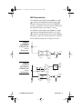
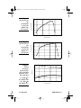
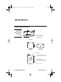
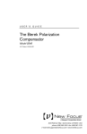
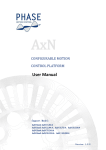
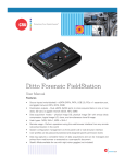
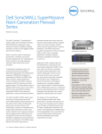
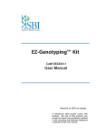
18X1 HS rcvr rev G.fm Page 1 Thursday, September 20, 2001 2:08 PM
USER’S GUIDE
125-MHz Photoreceivers
Models 1801 and 1811
These photodetectors are sensitive to electrostatic
discharges and could be permanently damaged if
subjected to any discharges. Ground your-self
adequately prior to handling these detectors or
making connections. A ground strap provides the
most effective grounding and minimizes the
likelihood of electrostatic damage.
5215 Hellyer Ave. • San Jose, CA 95138-1001 • USA
phone: (408) 284–6808 • fax: (408) 284–4824
e-mail: [email protected] • www.newfocus.com
18X1 HS rcvr rev G.fm Page 2 Thursday, September 20, 2001 2:08 PM
Warranty
New Focus, Inc. guarantees its products to be free of defects for one year from
the date of shipment. This is in lieu of all other guarantees, expressed or implied,
and does not cover incidental or consequential loss.
Copyright 2001, New Focus, Inc. All rights reserved.
The
symbol and NEW FOCUS, Inc. are registered trademarks
of NEW FOCUS, Inc.
Document Number 180413 Rev. G
18X1 HS rcvr rev G.fm Page 3 Thursday, September 20, 2001 2:08 PM
Contents
Operation
5
Introduction . . . . . . . . . . . . . . . . . . . . . . . . . . . . . . . . . . . . . . . . . . . 5
Handling Precautions . . . . . . . . . . . . . . . . . . . . . . . . . . . . . . . . . . . 6
Using the Photodetector . . . . . . . . . . . . . . . . . . . . . . . . . . . . . . . . 6
Theory . . . . . . . . . . . . . . . . . . . . . . . . . . . . . . . . . . . . . . . . . . . . . . . . . 8
Characteristics
11
Physical Specifications . . . . . . . . . . . . . . . . . . . . . . . . . . . . . . . . . 11
Photodetector Specifications . . . . . . . . . . . . . . . . . . . . . . . . . . . 12
Customer Service
13
Technical Support . . . . . . . . . . . . . . . . . . . . . . . . . . . . . . . . . . . . . 13
Service . . . . . . . . . . . . . . . . . . . . . . . . . . . . . . . . . . . . . . . . . . . . . . . . 13
125-MHz Photoreceivers
Contents • 3
18X1 HS rcvr rev G.fm Page 4 Thursday, September 20, 2001 2:08 PM
4 • Contents
NEW FOCUS, Inc.
18X1 HS rcvr rev G.fm Page 5 Thursday, September 20, 2001 2:08 PM
Operation
Introduction
The New Focus Models 1801 and 1811 125-MHz, lownoise photoreceivers address the needs of the
photodetector community in the area of low-noise,
high-gain, RF photoreception. These photoreceivers
are available either DC or AC coupled. Their typical
bandwidth is 125 MHz with a current gain of 40 V/
mA.
The performance of these units is achieved through
the use of solid RF design together with the
implementation of some of the latest advances in
commercially available amplifier chips. The detector is
shielded to avoid RF pickup. New Focus offers two
models to match your different wavelength needs. The
specifications at the rear of the manual list each
model’s characteristics.
These units address nearly all of the general purpose
needs of the RF photoreception community. They all
have a very large gain−bandwidth product, low noise,
high drive capability and a large dynamic range. These
receivers will enable wide bandwidth low-noise
detection of signals distributed over fiber-optic cables
or found in high resolution spectroscopy, fiber-optic
sensors, optical metrology, and many other
applications.
125-MHz Photoreceivers
Operation • 5
18X1 HS rcvr rev G.fm Page 6 Thursday, September 20, 2001 2:08 PM
Handling Precautions
Whenever handling the photoreceiver, make sure to
follow these precautions:
•
Prior to handling the unit or making connections,
be sure to ground yourself adequately—even small
electrostatic discharges could permanently damage the device. A ground strap provides the most
effective grounding and minimizes the likelihood
of electrostatic damage.
•
Make sure the optical connector is clean and
undamaged before connecting it to the detector
module.
Using the Photodetector
To obtain optical input:
1. Plug one end of the power cable to the connector on the back of the module and the other end
into a ±15-V power supply. (We recommend the
New Focus Model 0901 power supply.) Turn on
the supply.
Two different power cables have been shipped
with your detector: a Model 0921 banana plug-tomicroconnector cable and a Model 0922
microconnector-to-microconnector cable. If you
have a New Focus Model 0901 power supply, use
the Model 0922 cable on one of the supply’s 0.3-A
microconnector outputs. Do not use the Model
0921 on the Model 0901 power supply’s 0.1-A
banana outputs since they do not provide enough
current for the receiver. Use the Model 0921 cable
only with a power supply other than the 0901
6 • Operation
NEW FOCUS, Inc.
18X1 HS rcvr rev G.fm Page 7 Thursday, September 20, 2001 2:08 PM
providing a minimum of 0.25 A of current on ±15
V. The convention of the three banana plugs is:
Banana Plug
Voltage
Red
+15 V
Green
COM/GND
Black
-15 V
2. Turn on the optical beam.
3. For free-space beam input, align the module so
that the beam is incident on the detector surface.
For fiber-optic input, connect the fiber-optic cable
from your optical source to the FC input
connector on the front of the module. The
detector is designed to receive an FC/PC
connectorized fiber.
Note:
To operate the receiver in the linear region, keep the input power
levels well below the cw saturation power specification on
page 12. (The input power is wavelength dependent and is
inversely proportional to the responsivity.)
To set up the output connection:
1. If your RF measurement instrument has a male
connector, connect it directly to the SMA female
output connector (labeled “AC” on AC-coupled
units) on the back of the module.
2. If your instrument has a female connector, connect with the appropriate cable.
3. On AC-coupled units, monitor the DC bias on
the output labeled “DC” with the provided SMBto-BNC cable.
125-MHz Photoreceivers
Operation • 7
18X1 HS rcvr rev G.fm Page 8 Thursday, September 20, 2001 2:08 PM
Theory
The Model 1801 photoreceiver contains a silicon/PIN
photodiode. The Model 1811 contains an InGaAs/PIN
photodiode. In both models, the photodiode is followed by a low-noise transimpedance amplifier acting
as a pre-amp with a compensating amplifier as the output stage. A functional block diagram of the DC-coupled version is shown in Figure 1.
The AC-coupled versions incorporate two extra
blocking capacitors, a choke, and a DC bias monitor
circuit. The corner frequency of the high-pass filter on
the AC-coupled output is approximately 25 kHz. The
corner frequency of the low-pass filter on the DC bias
monitor output is approximately 50 kHz. Refer to
Figure 2 for a functional block diagram.
The compensating amplifier allows us to use a largearea diode, which is intrinsically low speed, while
maintaining a large bandwidth with flat response. This
is accomplished by having the gain of the output stage
increase with frequency. As a result of the increasing
gain the noise floor of the receiver increases starting at
approx. 40 MHz and having a soft peak at approximately 110 MHz. The equivalent input noise current at
the peak is greater than the low-frequency noise by a
factor of 10. Typical frequency response and noise
floor is shown in Figure 5.
The transimpedance amplifier in the AC path has an
absolute maximum input current of 5 mA and
therefore the maximum input optical power is 7 mW.
Figure 3 and Figure 4 show the responsivity of the
photodiodes. Power is delivered through a connector
on the back of the unit and the entire package is
shielded to eliminate RF pickup.
8 • Operation
NEW FOCUS, Inc.
18X1 HS rcvr rev G.fm Page 9 Thursday, September 20, 2001 2:08 PM
NEP Characteristics
For Model 1801, the NEP from 0–10 MHz is 3.3 pW/
Hz and from 10–200 MHz the NEP is 30 pW/ Hz .
Therefore the integrated noise from 0–130 MHz is
328 nWrms and with a conversion gain of 2.4x10⁴ V/W,
the expected output noise voltage is 7.8 mVrms.
For Model 1811, the NEP from 0–10 MHz is 2.5 pW/
Hz and from 10–200 MHz the NEP it is 22.5 pW/
Hz . Therefore the integrated noise from 0–130 MHz
is 246 nWrms and with a conversion gain of 2.4x10⁴ V/
W, the expected output noise voltage is 5.9 mVrms.
Figure 1:
Functional
block diagram
of Models 1801
& 1811
(DC Versions).
Vb
Optical Input
Output
I-V
G(f)
Transimpedance
Amplifier
Figure 2:
Functional
block diagram
of Models 1801
& 1811
(AC Versions).
Compensating
Difference
Amplifier
DC Bias
Monitor
Output
Vb
I-V
Optical Input
V
V-
+
Transimpedance
Amplifier
(low-speed)
Low-Pass Filter
50 kHz
AC-Coupled
Output
I-V
Transimpedance
Amplifier
125-MHz Photoreceivers
G(f)
Compensating
Difference
Amplifier
Operation • 9
18X1 HS rcvr rev G.fm Page 10 Thursday, September 20, 2001 2:08 PM
0.6
Responsivity, A/W
Figure 3:
Responsivity of
the
photodiode
used in the
Model 1801
(DC Version).
0.4
0.2
0.0
400
600
800
1000
1200
Wavelength, nm
1.00
Responsivity, A/W
Figure 4:
Responsivity of
the
photodiode
used in the
Model 1811
(DC Version)
0.80
0.60
0.40
0.20
0.00
800
1000
1200
1400
1600
1800
160
200
Figure 5:
Typical
frequency
response (top)
and noise floor
(bottom). At DC
the noise floor
is 3.3 pW/ Hz
for Model 1801
& 2.5 pW/ Hz
for Model 1811
10 • Operation
10 dB/div
Wavelength, nm
0
40
80
120
Frequency, MHz
NEW FOCUS, Inc.
18X1 HS rcvr rev G.fm Page 11 Thursday, September 20, 2001 2:08 PM
Characteristics
Physical Specifications
Figure 6:
Mechanical
drawings of the
Model 18X1
casing
3.00 (76.2)
18X1
2.07
(52.7)
Made in USA
1.00
(25.4)
Distance from window
face to photodetector:
1801 2.5 mm
1811 0.5 mm
Front View
2.86 (72.6)
Side View
1.43
(36.3)
Back View
8-32 (M4) thread
DC bias output; SMB connector
(included with AC versions only)
SMA connector;
AC-coupled output (AC version)
DC-coupled output (DC version)
Power connector
Bottom View
125-MHz Photoreceivers
Characteristics • 11
18X1 HS rcvr rev G.fm Page 12 Thursday, September 20, 2001 2:08 PM
Photodetector Specifications
Model #
1801
1811
Wavelength Range
300–1050 nm
900–1700 nm
Coupling
DC or AC
DC or AC
3-dB Bandwidth
(DC versions)
DC–125 MHz (typical)
DC–125 MHz (typical)
3-dB Bandwidth
(AC versions)
25 kHz–125 MHz (typ.)
25 kHz–125 MHz (typ.)
DC Bias Monitor Bandwidth
(AC versions only)
DC–50 kHz (typical)
DC–50 kHz (typical)
Risetime
3 ns (typical)
3 ns (typical)
Transimpedance Gain
(AC-coupled version)
40 V/mA (AC)
1 V/mA (DC)
40 V/mA (AC)
1 V/mA (DC)
Transimpedance Gain
(DC-coupled version)
40 V/mA
40 V/mA
Output Impedance
50 Ω
50 Ω
Minimum NEP*
3.3 pW/ Hz
2.5 pW/ Hz
CW Saturation Power
120 µW @ 950 nm
120 µW @ 950 nm
Maximum Pulse Power
5 mW
5 mW
Detector Material/Type
Silicon/PIN
InGaAs/PIN
Detector Diameter
0.8 mm
0.3 mm (FS)
0.1 mm (FC)
Power Requirements
±15 V DC; 250 mA
±15 V DC; 250 mA
Optical Input
FC or free space (FS)
FC or free space (FS)
RF Output
SMA
SMA
DC Bias Monitor output
(AC-coupled units only)
SMB
SMB
* NEP is frequency dependent. See page 9 for more details.
12 • Characteristics
NEW FOCUS, Inc.
18X1 HS rcvr rev G.fm Page 13 Thursday, September 20, 2001 2:08 PM
Customer Service
Technical Support
Information and advice about the operation of any
New Focus product is available from our applications
engineers. For quickest response, ask for “Technical
Support” and know the model and serial numbers for
your product.
Hours: 8:00–5:00 PST, Monday through Friday
(excluding holidays).
Toll Free: 1-866-NUFOCUS (1-866-683-6287)
(from the USA & Canada only)
Phone: (408) 284-6808
Support is also available by fax and email:
Fax: (408) 980-8883
Email: [email protected]
We typically respond to faxes and email within one
business day.
Service
In the event that the photoreceiver malfunctions or
becomes damaged, please contact New Focus for a
return authorization number and instructions on
shipping the unit back for evaluation and repair.
125-MHz Photoreceivers
Customer Service • 13
18X1 HS rcvr rev G.fm Page 14 Thursday, September 20, 2001 2:08 PM
14 • Customer Service
NEW FOCUS, Inc.