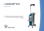
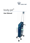
Download body-jet® ECO User Manual
Transcript
User Manual „In this world, there is nothing softer and thinner than water. But to compel the hard and unyielding it has no equal.“ (Laozi) ISO 13485 User manual for body-jet® eco Item no.: 500000-8 All rights to these operating instructions are reserved, in particular the rights of reproduction, distribution and translation. No part of these operating instructions may be reproduced in any form whatsoever (photocopy, microfilm or any other process), or processed, reproduced or distributed using electronic systems without the prior written permission of Human Med. The information included in these operating instructions may be amended or supplemented without prior notification and does not represent any obligation on the part of Human Med. Printed by Human Med AG Printed in Germany Copyright © Human Med AG; Wilhelm-Hennemann-Straße 9, 19061 Schwerin, Germany; 2014 Human Med AG ® User manual body-jet eco Doc-No.: 900071 Rev./ Date: 0/27-05-2014 Doc-No.: 900071 Rev./ Date: 0/27-05-2014 Human Med AG ® User manual body-jet eco Table of contents 1. General description of the body-jet® eco 1-2 1.1. Medical indication 1-2 1.2. Contraindications 1-2 2. Safety precautions and safety features 2-2 2.1. Significance of the safety symbols 2-2 2.2. Adherence to the safety instructions 2-2 2.3. Safety of the equipment and instruments 2-2 2.4. Safe practice by medical staff 2-3 2.5. Significance of the user manual and training of medical staff 2-3 2.6. Electrical safety and electromagnetic compatibility 2-4 2.7. Prevention of electrical shock 2-4 2.8. Particular safety instructions for use of the body-jet® eco 2-5 3. Description of the body-jet® eco 3-2 3.1. Functions and operating elements of the body-jet® eco 3-2 3.1.1. Functional elements 3-2 3.1.2. Control elements for device operation 3-3 3.1.3. Functional elements of the suction unit 3-4 3.1.4. Device label, meaning of device label symbols and other symbols 3-7 3.2. Description of the Biofill applicator and the Biofill cannula 3-9 3.2.1. Elements of the sterile single-use Biofill applicator 3-9 3.2.2. Instructions for the use of the Biofill cannula Human Med AG ® User manual body-jet eco Doc-No.: 900071 Rev./Date: 0/27-05-2014 3-10 Page 1 Table of contents Page 2 4. Preparatory activities 4-2 4.1. Installation of the body-jet® eco 4-2 4.1.1. Ambient conditions 4-2 ® 4.1.2. Installation of the body-jet eco 4-3 4.1.3. Components / device combination 4-4 4.1.4. Preparations for use 4-5 4.2. OP preparations 4-5 4.2.1. Test of the overflow/ bacteria barrier 4-5 4.2.2. Preparation of the suction unit 4-7 4.2.3. Vacuum check 4-9 4.2.4. Connection of the Biofill applicator 4-10 4.2.4.1. Installation of the infiltration pump 4-10 4.2.4.2. Connection of the Biofill applicator to the fluid bag 4-12 4.2.4.3. Connection of the suction tube of the Biofill applicator 4-14 4.2.5. Venting of the Biofill applicator 4-15 4.2.6. Connection of the FillerCollector ® 4-15 5. Working with the body-jet® eco 5-2 5.1. Activation of the water-jet 5-2 5.2. Activation of the vacuum buildup 5-2 5.2.1. Display of the actual vacuum level 5-2 5.3. Attachment of a Biofill cannula and water-jet test 5-3 Doc-No.: 900071 Rev./Date: 0/27-05-2014 Human Med AG ® User manual body-jet eco Table of contents 5.4. During surgery 5-5 5.5. After surgery 5-7 6. Troubleshooting 6-2 6.1. Faults of suctioning and water-jet generation 6-2 6.2. Applicator coding 6-5 7. Cleaning, disinfection, transport and storage after OP 7-2 7.1. Cleaning and disinfection after OP 7-2 7.1.1. Before cleaning and disinfection 7-2 7.1.2. Cleaning and disinfection 7-2 7.1.3. After cleaning and disinfection 7-4 7.2. Storage and transport 7-5 8. Technische Daten 8-2 8.1. General data of the body-jet® eco 8-2 8.2. Manufacturer’s declaration on electromagnetic compatibility 8-3 8.2.1. Guidance and manufacturer’s declaration – Electromagnetic emissions 8-3 8.2.2. Guidance and manufacturer’s declaration – Electromagnetic immunity Recommended separation distances between portable and mobile RF communications equipment and the body-jet® eco 8-4 9. Maintenance, warranty, disposal and customer service 9-2 9.1. Maintenance 9-2 9.1.1. Authorized persons 9-2 8.2.3. Human Med AG ® User manual body-jet eco Doc-No.: 900071 Rev./Date: 0/27-05-2014 8-6 Page 3 Table of contents Page 4 9.1.2. Functionality tests and inspection of safety-relevant features 9-2 9.1.3. Modifications and replacement of components 9-3 9.1.4. Periodic maintenance 9-3 9.2. Warranty 9-3 9.3. Disposal 9-4 9.4. Customer service 9-4 Doc-No.: 900071 Rev./Date: 0/27-05-2014 Human Med AG ® User manual body-jet eco Chapter 1 - General description of the body-jet® eco Contents 1. General description of the body-jet® eco ...................................................................................................................................... 2 1.1. Medical indication .......................................................................................................................................................................... 2 1.2. Contraindications ........................................................................................................................................................................... 2 Human Med AG ® User manual body-jet eco Doc-No.: 900071 Rev./Date: 0/27-05-2014 Page 1-1 Chapter 1 - General description of the body-jet® eco 1. General description of the body-jet® eco The body-jet® eco is the new model of the body-jet® series. It was specifically designed for reconstructive surgery applications in hospitals as well as in dermatology clinics, e.g. for autologous fat harvesting for soft tissue corrections and wrinkle smoothing. The body-jet® eco generates a gentle pulsating water jet that helps to detach the fat cells from the surrounding tissue and aspirates the detached fat cells. With this method, the fat cells are not damaged so that the harvested fat can be used for autologous fat grafting in aesthetic-plastic surgery applications. As protection for the patient, the body-jet® eco features a system function precluding the reuse of the Biofill applicators and the use of Biofill applicator copies. 1.1. Medical indication The body-jet® eco is intended to be used for harvesting natural body fat for autologous fat grafting and lipofilling. 1.2. Contraindications The body-jet® eco and the instruments to be connected are not approved for intra-cardiac application. The body-jet® eco must not be used in patients with severe coagulation disorders. Page 1-2 Doc-No.: 900071 Rev./Date: 0/27-05-2014 Human Med AG ® User manual body-jet eco Chapter 2 - Safety precautions and safety features Contents 2. Safety precautions and safety features......................................................................................................................................... 2 2.1. Significance of the safety symbols ................................................................................................................................................. 2 2.2. Adherence to the safety instructions .............................................................................................................................................. 2 2.3. Safety of the equipment and instruments ...................................................................................................................................... 2 2.4. Safe practice by medical staff ........................................................................................................................................................ 3 2.5. Significance of the user manual and training of medical staff ........................................................................................................ 3 2.6. Electrical safety and electromagnetic compatibility ........................................................................................................................ 4 2.7. Prevention of electrical shock ........................................................................................................................................................ 4 2.8. Particular safety instructions for use of the body-jet® eco .............................................................................................................. 5 Human Med AG ® User manual body-jet eco Doc.-No.: 900071 Rev./Date: 0/27-05-2014 Page 2-1 Chapter 2 - Safety precautions and safety features 2. Safety precautions and safety features 2.1. Significance of the safety symbols This symbol characterizes a hazard that may cause personal injury. This symbol characterizes a hazard that may cause material damage. This symbol characterizes a hazard that may cause a failure or malfunction of the medical device. Please pay particular attention to the safety precautions in each chapter. 2.2. Adherence to the safety instructions Appropriate application of and compliance with the safety instructions considerably contributes to the safety of the user, of the patients and the environment. 2.3. Safety of the equipment and instruments The body-jet® eco complies with all relevant and generally accepted engineering practices as well as with the applicable occupational protection and accident prevention regulations. Page 2-2 Doc.-No.: 900071 Rev./Date: 0/27-05-2014 Human Med AG ® User manual body-jet eco Chapter 2 - Safety precautions and safety features 2.4. Safe practice by medical staff Working with medical equipment is basically associated with certain risks to medical staff and patients. Risks cannot be entirely eliminated by design features alone. Safety does not depend solely on the equipment but to a large extent on factors influenced by its user. These factors are dealt with in the safety information of this chapter. 2.5. Significance of the user manual and training of medical staff The user manual represents an important element in the safety design concept of the body-jet® eco. Therefore, every medical professional who is concerned with preparation, setup, operation, disassembly, cleaning and disinfection, of the device and instruments must read the user manual and the instructions for use of the instruments. This user manual is an inherent part of the device. Every user must be familiar with the instructions included herein. Keep these instructions in the manual. Keep this manual in a safe but easily accessible place so that it is available to users at all times. The users/ operators, normally qualified medical staff, must have experience in clinical use of this device and its accessories and must acquire sufficient knowledge of the device by means of literature or test runs prior to use. Only qualified medical staff who has been properly trained in operation and handling of this equipment is allowed to use the body-jet® eco in strict adherence to the present user manual. The training must be performed only by personnel who are suitable on the basis of their knowledge and practical experience. Human Med assumes no liability for any damage resulting from using the device without instruction or through improper use. In case of any uncertainty or question, please contact Human Med. We will be glad to give you further assistance and to receive your suggestions concerning this user manual. Human Med AG ® User manual body-jet eco Doc.-No.: 900071 Rev./Date: 0/27-05-2014 Page 2-3 Chapter 2 - Safety precautions and safety features 2.6. Electrical safety and electromagnetic compatibility The device must be connected to a grounded mains supply in accordance with the applicable national standards. The body-jet® eco has been tested by an accredited laboratory for immunity to interference and for electromagnetic compatibility. The test results are within the limits for medical electrical equipment as defined in standard IEC 60601-1-2. That means that this device is adequately immune to interference and cannot interfere with other devices, provided that it has correctly been installed and works properly. 2.7. Prevention of electrical shock The device complies with the requirements of standard IEC 60601-1 related to devices of protection class I and devices with applied parts of type BF. The supply voltage must be identical to the voltage stated on the type label on the rear side of the device. Connect the device to a properly installed and grounded outlet. Only use the power cord supplied with the device. Check the device and the delivered accessories (e.g. foot-bellows, cables, suction container) for damage prior to each use. Do not use a damaged device, a damaged cable or damaged accessories. Replace defective accessories. For spare parts or servicing please contact our customer service. For your own safety and that of your patients, never attempt to repair by yourself. Any modification to the equipment will exempt Human Med from liability. Page 2-4 Doc.-No.: 900071 Rev./Date: 0/27-05-2014 Human Med AG ® User manual body-jet eco Chapter 2 - Safety precautions and safety features 2.8. Particular safety instructions for use of the body-jet® eco The following instructions must be strictly observed: The direct water-jet may be dangerous due to a possible cutting effect depending on the pressure settings; and eyes and skin might be injured. Every medical professional operating the device must previously be instructed and acquainted with operational parameters. The Biofill Applicator and the used Biofill cannula must not be directed towards the eyes. When working with the device, the foot-bellows have to be secured against unintentional actuation. When attaching the cannula handle, take care that the water jet is only directed towards the operating field. Operational safety The device must be installed and initially put into operation only by qualified staff that has been trained by Human Med or their authorized representatives on how to put into operation and install the necessary components, as well as how to connect the accessories required for medical application. The device is only to be used after: delivery and ready-to-operate installation of the device by the service team of Human Med or their authorized representatives; completion of all safety measures outlined in this user manual; the user is fully conversant with mastering functional procedures and operation of the device in case of malfunctions. Human Med AG ® User manual body-jet eco Doc.-No.: 900071 Rev./Date: 0/27-05-2014 Page 2-5 Chapter 2 - Safety precautions and safety features Every medical professional who operates the device is fully responsible for implementing all safety measures required to ensure that the patient, the surgeon and all other attendees are not exposed to danger during operation of the device. Before using the body-jet® eco, each user must become fully conversant with the use of the water-jet and the vacuum needed for suctioning by studying related literature or carrying out test runs. Safety features Safe and reliable operation of the body-jet® eco is ensured by a series of built-in safety features: The device has been designed in a way that serious operating errors are excluded. The vacuum level and the infiltration flow are limited owing to the design of the device and the Biofill applicator. A barcode system helps to prevent the reuse of the Biofill applicators designed as single-use products. Page 2-6 Doc.-No.: 900071 Rev./Date: 0/27-05-2014 Human Med AG ® User manual body-jet eco Chapter 3 - Description of the body-jet® eco Contents 3. Description of the body-jet® eco .................................................................................................................................................... 2 3.1. Functions and operating elements of the body-jet® eco................................................................................................................. 2 3.1.1. Functional elements ................................................................................................................................................................... 2 3.1.2. Control elements for device operation........................................................................................................................................ 3 3.1.3. Functional elements of the suction unit ...................................................................................................................................... 4 3.1.4. Device label, meaning of device label symbols and other symbols ............................................................................................ 7 3.2. Description of the Biofill applicator and the Biofill cannula ............................................................................................................. 9 3.2.1. Elements of the sterile single-use Biofill applicator .................................................................................................................... 9 3.2.2. Instructions for the use of Biofill cannulae ................................................................................................................................ 10 Human Med AG ® User manual body-jet eco Doc-No.: 900071 Rev./Date: 0/27-05-2014 Page 3-1 Chapter 3 - Description of the body-jet® eco 3. Description of the body-jet® eco 3.1. Functions and operating elements of the body-jet® eco 3.1.1. Functional elements 1 Rack with hook for the fluid bag 2 Control panel for device operation 3 Supporting arm for FillerCollector® (optional): to secure the collection container against tipping over and to keep a defined distance towards the device 4 Suction container including suction bag with angle connector 5 Connection port for foot-bellows used to activate the water-jet 6 Eject button: to unlock the infiltration pump for removal 7 Sealing cap: to keep the infiltration pump in the socket and seal the socket 1 3 2 4 5 6 7 ® Fig. 3-1: body-jet eco, front view Page 3-2 Doc-No.: 900071 Rev./Date: 0/27-05-2014 Human Med AG ® User manual body-jet eco Chapter 3 - Description of the body-jet® eco 1 Rack holder 2 Master switch including fuse: to switch the device on and off. „0“ – The device is switched off. „I“ – The device is switched on. 3 Potential equalizing plug 4 Power connection: with integrated mains fuse for power plug and cord to supply the device with electrical power 1 Display of the operational state of the device (human med logo) 2 LED light bar indicates the actual vacuum 3 ON/OFF button VACUUM: to activate/ deactivate the vacuum buildup 4 ON/OFF button FLOW: to activate/ deactivate the water-jet 1 2 3 4 ® Fig. 3-2: body-jet eco, rear view 3.1.2. Control elements for device operation 1 2 3 4 ® Fig. 3-3: Control elements of the body-jet eco The LED of the logo signals the current operating state of the device. Human Med AG ® User manual body-jet eco Doc-No.: 900071 Rev./Date: 0/27-05-2014 Page 3-3 Chapter 3 - Description of the body-jet® eco The logo is flashing: The Biofill applicator has not been identified by the device control as valid applicator; the water-jet cannot be activated yet. The logo lights up continuously: The Biofill applicator has been identified as valid; the water-jet can be activated now. 3.1.3. Functional elements of the suction unit There is one suction container attached to the body-jet® eco to house the disposable suction bag (Fig. 3-4 and Fig. 3-5). The suction bag is inserted into the suction container and is used for collection of the excessive aspirate. 1 2 3 4 1 Suction bag with lid 2 Suction container 3 Vacuum tube with overflow / bacteria barrier and vacuum elbow connector 4 Plug-in coupling connector 5 Suction port 5 Fig. 3-4: Suction unit Page 3-4 Doc-No.: 900071 Rev./Date: 0/27-05-2014 Human Med AG ® User manual body-jet eco Chapter 3 - Description of the body-jet® eco 10 7 6 8 9 6 Vacuum elbow connector 7 Angle connector 8 Connection port “PATIENT” 9 Closing cap 10 Grip of the suction bag Fig. 3-5: Suction unit The suction container (2) is to be connected to the suction port (5) of the device via a vacuum elbow connector (6), a vacuum tube with overflow/ bacteria barrier (3) and a plug-in coupling connector (4). The vacuum tube with overflow/ bacteria barrier, the plug-in coupling connector and the vacuum elbow connector are included in the scope of supply of the device. The suction container is intended for exclusive use with a suction bag. A trouble-free suctioning can only be guaranteed when a 1000 ml suction bag with angle connector (made by Serres Oy, Art.-Nr.: 57157) is used. Never connect a suction tube directly to the suction port (5)! The connection port (8) for the suction tube of the Biofill applicator is marked “PATIENT”. The vacuum tube with overflow/ bacteria barrier (Fig. 3-6) is connected to the suction port (5) of the body-jet® eco by means of a plug-in coupling connector. Human Med AG ® User manual body-jet eco Doc-No.: 900071 Rev./Date: 0/27-05-2014 Page 3-5 Chapter 3 - Description of the body-jet® eco This symbol signifies that the following number is the batch code of the product. This symbol indicates the maximum date until which the product may be used. Fig. 3-6: Overflow/ bacteria barrier Never use the body-jet® eco without overflow/ bacteria barrier! The proper functioning of the overflow/ bacteria barrier must be checked on each surgery/ treatment day (see Chapter 4.2.2 “Preparation of the suction unit” on page 4-6). In case of improper function replace the overflow/ bacteria barrier. Page 3-6 Doc-No.: 900071 Rev./Date: 0/27-05-2014 Human Med AG ® User manual body-jet eco Chapter 3 - Description of the body-jet® eco 3.1.4. Device label, meaning of device label symbols and other symbols Fig. 3-7: Device label Fig. 3-8: Fuse label The device label (Fig. 3-7) is to be found on the rear side of the device. It carries technical information and symbols that must not be ignored by any user of the device. The fuse label (Fig. 3-8) is placed directly on the device plug, where the fuses are installed. The label indicates the fuse parameters. The meaning of the symbols is explained in the following: This symbol signifies that the device is equipped with a laser system that emits potentially hazardous radiation. This label indicates that the integrated laser system is a laser equipment of class 2. This means that the available laser radiation is still within the visible spectrum (400 nm to 700 nm) and not dangerous to the eyes provided that the time of exposure to radiation does not exceed 0,25 s (eyelid reflex). Nevertheless, avoid looking directly into the laser beam. This symbol signifies that the user manual and other relevant instructions must be read and followed. Human Med AG ® User manual body-jet eco Doc-No.: 900071 Rev./Date: 0/27-05-2014 Page 3-7 Chapter 3 - Description of the body-jet® eco This symbol signifies that sitting on the device is forbidden. This symbol refers to the date of manufacture of the device. This symbol signifies that the device must be separately disposed of at the end of its service life in accordance with the Council Directive 2002/96/EC of 27 January 2003 on waste of electrical and electronic equipment (WEEE). The device can also be returned to Human Med for proper disposal. This symbol signifies that the device is in conformity to the specifications of the Council Directive 93/42/EEC for medical products; and the manufacturer works with a quality assurance system monitored by the Notified Body no. 0482. There is another label directly right next to the socket of the infiltration pump: This symbol means that the device is equipped with an applied part of type BF (Biofill applicator) and complies with the requirements of standard IEC 60601-1 relating on protection. The device must not be transported outside the OP area with fluid bags still attached. The rack and the supporting arm for the FillerCollector® must be removed before. Page 3-8 Doc-No.: 900071 Rev./Date: 0/27-05-2014 Human Med AG ® User manual body-jet eco Chapter 3 - Description of the body-jet® eco 3.2. Description of the Biofill applicator and the Biofill cannula The Biofill applicator (Fig. 3-9) is delivered in sterile condition (EO sterilization). Faulty Biofill applicators must not be used; a resterilization is not allowed. The Biofill applicator is an applied part of type BF and intended for single use only. Please observe the information given in the package leaflet. 3.2.1. Elements of the sterile single-use Biofill applicator A Hand-piece with nozzle capillary tube: is used for introduction of the infiltration fluid into the body area concerned and for transport of adipose tissue. B Pricking pin with protection cap: is used for connection of the transfer tubing set to the fluid bag. C Tube clamp of the transfer tubing set: is used interrupting the fluid supply into the Biofill applicator (by closing) if required. D Transfer tubing set with two transfer tubes: is used for transport of the infiltration fluid from the fluid bag to the infiltration pump. E Tube socket: Is used for attachment of the suction tube (F) to the suction bag or to the FillerCollector®. F Suction tube: Is used for connection of the hand-piece with the suction bag or the FillerCollector® and for transport of the aspirate either into the suction container or into the collection container of the FillerCollector®. C D C A B H B F E G Fig. 3-9 Biofill applicator Human Med AG ® User manual body-jet eco Doc-No.: 900071 Rev./Date: 0/27-05-2014 Page 3-9 Chapter 3 - Description of the body-jet® eco G Infiltration pump with piston: Is used for generation of the waterjet pressure needed. H Infiltration tube: Is used for transport of the pressurized infiltration fluid from the infiltration pump (G) to the hand-piece (A) of the Biofill applicator. 3.2.2. Instructions for the use of the Biofill cannula The Biofill cannulae (Fig. 3-) are normally delivered unsterile and must be thoroughly cleaned and sterilized before use according to the accompanying processing instructions. Detailed instructions on cleaning, disinfection and sterilization of the Biofill cannulae can be found in the leaflets included in the packaging. The Biofill cannulae are used for infiltration of the tumescent fluid as well as for aspiration of the adipose tissue. The Biofill cannulae have several suction openings and one bypass hole in their handle. By closing this bypass hole the suctioning is started; by opening it the suctioning is stopped. K I I Biofill cannula K Bypass hole Fig. 3-10: Biofill cannula for use with the Biofill applicator Page 3-10 Doc-No.: 900071 Rev./Date: 0/27-05-2014 Human Med AG ® User manual body-jet eco Chapter 4 - Preparatory activities Contents 4. Preparatory activities .................................................................................................................................................................. 2 4.1. Installation of the body-jet® eco ..................................................................................................................................................... 2 4.1.1. Ambient conditions ..................................................................................................................................................................... 2 4.1.2. Installation of the body-jet® eco .................................................................................................................................................. 3 4.1.3. Components / device combination ............................................................................................................................................. 4 4.1.4. Preparations for use ................................................................................................................................................................... 5 4.2. OP preparations ............................................................................................................................................................................ 5 4.2.1. Test of the overflow/ bacteria barrier .......................................................................................................................................... 5 4.2.2. Preparation of the suction unit ................................................................................................................................................... 7 4.2.3. Vacuum check ........................................................................................................................................................................... 9 4.2.4. Connection of the Biofill applicator ........................................................................................................................................... 10 4.2.4.1. Installation of the infiltration pump ............................................................................................................................................................ 10 4.2.4.2. Connection of the Biofill applicator to the fluid bag ................................................................................................................................... 12 4.2.4.3. Connection of the suction tube of the Biofill applicator .............................................................................................................................. 14 4.2.5. Venting of the Biofill applicator ................................................................................................................................................. 15 4.2.6. Connection of the FillerCollector® ............................................................................................................................................ 15 Human Med AG ® User manual body-jet eco Doc-No.: 900071 Rev./Date: 0/27-05-2014 Page 4-1 Chapter 4 - Preparatory activities 4. Preparatory activities 4.1. Installation of the body-jet® eco 4.1.1. Ambient conditions No operation in explosion hazard zones Only use the equipment in rooms used for medical purposes. Do not operate the device in explosion hazard zones in which flammable anesthetics, combustible skin cleaners or disinfectants are used. Operating conditions Only operate the equipment at temperatures and air humidity conditions as specified in chapter 8 „Technical Data“ on page 8-3. Exceeding the indicated tolerances may lead to breakdown of the installed equipment. Ventilation The equipment must be placed in a way ensuring that air can freely circulate around the system housing. The installation in narrow alcoves is not allowed. Exposure to liquids The equipment housing is not entirely water-tight. Therefore, be careful not to spill liquids around or on the equipment. Do not install the device in direct proximity of hoses or bins containing liquid. Page 4-2 Doc-No.: 900071 Rev./Date: 0/27-05-2014 Human Med AG ® User manual body-jet eco Chapter 4 - Preparatory activities Power cord and power outlet The supply voltage must be identical to the voltage indicated on the type label on the rear side of the body-jet® eco. Connect the device to a grounded outlet. Only use the power cord supplied with the device. Run the power cord from the device to the outlet in a way that hazardous situations (e.g. tripping) are eliminated. For safety reasons do not use any extension leads or power distribution units. Do not connect the device to the power supply neither use it, if it is in defective conditions that cannot be properly remedied in a professional manner. 4.1.2. Installation of the body-jet® eco To ensure its stability, place the body-jet® eco on a suitable equipment table approved for surgeries. For thermal reasons and adequate display legibility the device must not be exposed to direct sunlight. Always keep a safety distance of at least 1 m between the device and the sterile areas, particularly the instrument tables, operating tables and staff in sterile garment. In order to place the FillerCollector® in a stable and safe manner and to keep a defined distance between the sterile collection container and the device, we recommend using the supporting arm. Never mount the FillerCollector® directly onto the device; only by means of the supporting arm. Do not lean on the supporting arm. Human Med AG ® User manual body-jet eco Doc-No.: 900071 Rev./Date: 0/27-05-2014 Page 4-3 Chapter 4 - Preparatory activities 4.1.3. Components / device combination Only use the body-jet® eco together with components that are specified by Human Med in this user manual. This particularly applies to the following parts: Foot-bellows with suitable tubing (produced by Herga Electric Ltd., item no. of the one-sided footbellows: 6448-AAAC-0000; item no. of the double-sided foot-bellows: 6448-EAAC-0000), 1000 ml suction container (produced by Serres Oy, item no. 57308), 1000 ml suction bag (produced by Serres Oy, item no. 57157), Hydrophobic filter set incl. vacuum hose with overflow/ bacteria barrier (produced by Medela AG, item no. 077.0572), plug-in coupling connector and vacuum elbow connector for connecting the suction container to the suction port of the device), Sealing cap for the infiltration pump socket. In respect of the allowed medical indications the body-jet® eco must only be operated using the Biofill applicator (REF 580001) and the Biofill cannula (REF 580086) manufactured by Human Med. The use of an invalid applicator may lead to breakdown of the device. The current product list is applicable. Any modification to the body-jet® eco, the Biofill applicator, the Biofill cannulas and other accessories are not allowed and will result in exemption of Human Med from liability. Page 4-4 Doc-No.: 900071 Rev./Date: 0/27-05-2014 Human Med AG ® User manual body-jet eco Chapter 4 - Preparatory activities 4.1.4. Preparations for use Check the device and its components (e.g. including removable parts such as cord and foot-bellows) thoroughly for damage before use. Do not use a damaged device or damaged components. Check the guarantee seal between the housing cover and the device housing as well as the type label on the rear side of the device. The device must not be used, if any of the identification labels is damaged. Connect the device to a properly installed grounded outlet (Chapter 2.7 „Prevention of electrical shock“ on page 2-4). Connect the foot-bellows to the foot-bellows port. Switch the body-jet® eco on (I/O). The master switch for switching on and off is situated at the rear of the device (No. 2 in Fig. 3-2 in Chapter 3.1.1 „Functional elements“ on page 3-3). 4.2. OP preparations 4.2.1. Test of the overflow/ bacteria barrier Before using the suction unit of the body-jet® eco, first check the functions of the overflow/ bacteria barrier! Human Med AG ® User manual body-jet eco Doc-No.: 900071 Rev./Date: 0/27-05-2014 Page 4-5 Chapter 4 - Preparatory activities Attach the overflow/ bacteria barrier to the device. The vacuum elbow connector (6) must have been attached to the suction container (2); the plug-in coupling connector (4) must have been connected to the suction port (5). Fig. 4-1: Suction unit Activate the vacuum buildup by pushing the “ON/OFF” button VACUUM. The green-lighting LED signifies that the vacuum generation is active. Fig. 4-2: Activated ON/OFF button VACUUM If two LEDs of the light bar are illuminated, the overflow/ bacteria barrier may be blocked. Fig. 4-3: LED light bar for display of the vacuum level Page 4-6 Replace the filter (produced by Medela AG, Ref No. 077.0572) or the hydrophobic filter set (REF No. 101947, see current product list). Doc-No.: 900071 Rev./Date: 0/27-05-2014 Human Med AG ® User manual body-jet eco Chapter 4 - Preparatory activities 4.2.2. Preparation of the suction unit Unfold the suction bag (Fig. 4-5). Fig. 4-4: Unfold the suction bag Insert the suction bag into the suction container and firmly push down the lid of the suction container so that it fits tightly for proper sealing. Connect the vacuum tube with overflow/ bacteria barrier to the suction container by means of the vacuum elbow connector. Fig. 4-6: Suction container incl. suction bag and vacuum tube with overflow/ bacteria barrier Human Med AG ® User manual body-jet eco Doc-No.: 900071 Rev./Date: 0/27-05-2014 Page 4-7 Chapter 4 - Preparatory activities Attach the suction container to the device. Connect the vacuum tubing with overflow/ bacteria barrier to the suction port (Fig. 4-7). Fig. 4-7: Attach the suction container to the device Now the suction bag must be completely unfolded under vacuum pressure. For this, close the angle connector (7) with your finger (Fig. 4-8). 7 If the suction bag is not unfolded yet at once, take your finger off from the angle connector for a moment and then close it again. Repeat this procedure until the suction bag has been completely unfolded and lies against the inner surface of the suction container. Fig. 4-8: Insertion of the suction bag Prior to use, the suction container und the suction bag must always be checked for cracks and other damage. Either a damaged container or a damaged bag must not be used! Page 4-8 Doc-No.: 900071 Rev./Date: 0/27-05-2014 Human Med AG ® User manual body-jet eco Chapter 4 - Preparatory activities 4.2.3. Vacuum check 7 Make sure by closing the angle connector (7) of the suction bag with your finger that the required vacuum has been built up and the bag is completely unfolded (Fig. 4-9). Fig. 4-9: Close the angle connector of the suction bag Keep the angle connector (K) closed with your finger until the final vacuum level has been reached. When the final vacuum level has been reached, four LEDs of the light bar should be illuminated (Fig. 4-10). Fig. 4-10: LED light bar for display of the vacuum level If this level is not reached, read in chapter 6.1 „Faults of suctioning and water-jet generation“ on page 6-2. Please take also account of the altitude when checking the final vacuum level (Fig. 4-11). When the angle connector (7) is open, no more than two LEDs of the light bar should be illuminated; otherwise the suction bag must be replaced. Fig. 4-11: Maximum vacuum depending on altitude Human Med AG ® User manual body-jet eco Doc-No.: 900071 Rev./Date: 0/27-05-2014 Page 4-9 Chapter 4 - Preparatory activities 4.2.4. Connection of the Biofill applicator 4.2.4.1. Installation of the infiltration pump Take the Biofill applicator from the sterile packaging. Use only Biofill applicators from undamaged packaging. Take care to leave the hand-piece of the Biofill applicator in the sterile area and hand the connection parts over to the operator of the device. This medical product is exclusively intended for single use. Remove the sealing cap from the infiltration pump socket by turning it counterclockwise. Push the infiltration pump into the socket (Fig. 4-12). As soon as the used applicator has been identified by the barcode scanner as valid Biofill applicator, the water-jet generation is active. The logo LED stops flashing and changes to a continuous illumination. If the logo LED continues flashing, refer to chapter 6.2 „Applicator coding“ on page 6-5. Fig. 4-12: Push the infiltration pump into the socket NOTE: The period in which the water-jet generation is active, is limited to two hours. Never look directly into the infiltration pump socket! The barcode scanner remains active until the Biofill applicator has been identified. Page 4-10 Doc-No.: 900071 Rev./Date: 0/27-05-2014 Human Med AG ® User manual body-jet eco Chapter 4 - Preparatory activities The infiltration tube (1) of the Biofill applicator must lead upwards whereas the transfer tubes (2a and 2b) for the fluid supply must lead downwards (Fig. 4-13). Fig. 4-13: Correct position of the infiltration pump Now fix the sealing cap hand-tight by slightly turning it clockwise (Fig. 4-14). NOTE: The sealing cap must be fixed in a way that it cannot be taken off without turning it slightly counterclockwise. Fig. 4-14: Fix the sealing cap Human Med AG ® User manual body-jet eco Doc-No.: 900071 Rev./Date: 0/27-05-2014 Page 4-11 Chapter 4 - Preparatory activities 4.2.4.2. Connection of the Biofill applicator to the fluid bag Before venting, the Biofill applicator must be connected to the fluid bag via the transfer tubes. The fluid bag is to be attached to the hook on the rack. The weight of the fluid bag must not exceed 1000 g! In case fluid bottles or canisters are used, these must be vented properly. We recommend using fluid bags only. Each transfer tube is equipped with a clamp, a pricking pin and a protective cap. Close one transfer tube (2a) by means of the clamp (Fig. 4-15), but before remove the protection cap from its pricking pin. The transfer tube may be fixed onto the rack using the retaining clip provided there for this purpose. Fig. 4-15: Close the transfer tube Page 4-12 Doc-No.: 900071 Rev./Date: 0/27-05-2014 Human Med AG ® User manual body-jet eco Chapter 4 - Preparatory activities Remove the protection cap from the pricking pin of the second transfer tube (2b) and prick it into the fluid bag (Fig. 4-16). The clamp of this transfer tube (2b) remains open. Fig. 4-16: Connect the transfer tube to the fluid bag Now open the tube clamp of the first transfer tube (2a), in order to vent the tubing system (Fig. 4-17). As soon as the transfer tube (2a) is completely filled with fluid, reclamp it and put the protective cap on the pricking pin again. Fig. 4-17: Venting of the transfer tubing Human Med AG ® User manual body-jet eco Doc-No.: 900071 Rev./Date: 0/27-05-2014 Page 4-13 Chapter 4 - Preparatory activities If infiltration fluid is spilled onto the device or its components, wipe it off immediately and thoroughly with a soft cloth and warm water. 4.2.4.3. Connection of the suction tube of the Biofill applicator Push the socket of the suction tube (E) firmly onto the angle connector (7) of the suction bag (Fig. 4-18). Fig. 4-18: Attach the suction tube to the suction bag Push the other end of the suction tube onto the hand-piece of the Biofill applicator (Fig. 4-19). Fig. 4-19: Attach the suction tube to the hand-piece Page 4-14 Doc-No.: 900071 Rev./Date: 0/27-05-2014 Human Med AG ® User manual body-jet eco Chapter 4 - Preparatory activities 4.2.5. Venting of the Biofill applicator By pushing the ON/OFF button FLOW on the membrane keypad the water-jet will be ready for operation. The readiness for operation is indicated by the flashing LED. Fig. 4-20: Activated ON/OFF button FLOW Activate the water-jet by actuating the foot-bellows (the LED lights up continuously). The Biofill applicator is vented now and after a few seconds a straight spot-jet should come out of the nozzle capillary. If there is no straight spot-jet coming out of the capillary, the Biofill applicator doesn’t work properly and must be replaced. Take care to direct the water-jet into a suitable container when venting the Biofill applicator. Never direct the water-jet towards people! 4.2.6. Connection of the FillerCollector® We recommend using the FillerCollector® (Ref No. 660000) for harvesting, in an easy, safe and efficient manner, small adipose tissue volumes of up to 250 ml that may be used for autologous fat grafting immediately after liposuction with the body-jet® eco. The FillerCollector® is delivered as a set of several individual components. This set consists of sterile single-use and reusable components. The reusable parts have to be cleaned and sterilized prior to use. The cleaning/ sterilization procedure and the assembly are described in the current user manual and reprocessing instruction for the FillerCollector®. Human Med AG ® User manual body-jet eco Doc-No.: 900071 Rev./Date: 0/27-05-2014 Page 4-15 Chapter 4 - Preparatory activities A supporting arm (Fig. 4-21), to which the FillerCollector® is attached, ensures that the collection container is stable and cannot tip over. Furthermore, it helps to keep a defined distance between the sterile collection container and the device. Fig. 4-21: Holding arm for the FillerCollector ® The supporting arm is just pushed into the fixture provided for this on the device housing (Fig. 4-22). Fig. 4-22: Holding arm for FillerCollector Page 4-16 ® Doc-No.: 900071 Rev./Date: 0/27-05-2014 Human Med AG ® User manual body-jet eco Chapter 5 - Working with the body-jet® eco Contents 5. Working with the body-jet® eco .................................................................................................................................................. 2 5.1. Activation of the water-jet .............................................................................................................................................................. 2 5.2. Activation of the vacuum buildup ................................................................................................................................................... 2 5.2.1. Display of the actual vacuum level ............................................................................................................................................. 2 5.3. Attachment of a Biofill cannula and water-jet test .......................................................................................................................... 3 5.4. During surgery ............................................................................................................................................................................... 5 5.5. After surgery .................................................................................................................................................................................. 7 Human Med AG ® User manual body-jet eco Doc-No.: 900071 Rev./Date: 0/27-05-2014 Page 5-1 Chapter 5 - Working with the body-jet® eco 5. Working with the body-jet® eco 5.1. Activation of the water-jet By pushing the ON/OFF button FLOW the water jet will be set ready for operation. The blinking LED of the ON/OFF button indicates that the water jet is ready for operation. By pushing this button again the water jet is no longer ready for operation. The water jet is activated by actuation of the foot-bellows. When actuating the foot-bellows, the LED of the ON/OFF button FLOW is green. 5.2. Activation of the vacuum buildup The vacuum required for suctioning is preset to the value of -500 mbar. By pushing the ON/OFF button VACUUM the vacuum buildup is activated. The blinking LED of the ON/OFF button confirms the activation. By pushing this button again the vacuum buildup will be deactivated. 5.2.1. Display of the actual vacuum level The actual vacuum level is displayed as a LED light bar: 200 mbar – LED 1 300 mbar – LEDs 1 to 2 400 mbar – LEDs 1 to 3 500 mbar – LEDs 1 to 4 Page 5-2 Doc-No.: 900071 Rev./Date: 0/27-05-2014 Human Med AG ® User manual body-jet eco Chapter 5 - Working with the body-jet® eco 600 mbar – LEDs 1 to 5 The orange lighting LED indicates that an vacuum buildup error has occurred. The final vacuum level depends on the type of vacuum pump and the elevation above sea level (chapter 8 „Technical data“ on page 8-2). 5.3. Attachment of a Biofill cannula and water-jet test Before attaching the Biofill cannula, check whether the Biofill applicator generates a continuous straight spot jet. If the generated water jet doesn’t show the described pattern, the applicator must be replaced. Take care to direct the water jet into a suitable container when checking the Biofill applicator. Never direct the water jet towards people! Then attach the selected Biofill cannula to the hand-piece of the Biofill applicator (Fig. 5-1). RECOMMENDATION: Treat the inside of the Biofill cannula handle with surgical silicone spray before pushing the cannula onto the hand-piece of the Biofill applicator. Fig. 5-1: Attach the Biofill cannula to the hand-piece of the Biofill applicator Human Med AG ® User manual body-jet eco Doc-No.: 900071 Rev./Date: 0/27-05-2014 Page 5-3 Chapter 5 - Working with the body-jet® eco The water jet coming out of the nozzle now should be flat and fanshaped (Fig. 5-2). NOTE: The Biofill applicator must be used together with a Biofill cannula. You cannot infiltrate when using a cannula from other product lines. Fig. 5-2: Correct fan-shaped spray jet Before attaching the cannula to the hand-piece of the Biofill applicator, make sure that you are using the right cannula and that it is undamaged. Do not use damaged cannulae! Do not bend the Biofill cannula tube by more than 5°, otherwise it might break. A bent cannula must not be re-straightened, as this might cause the cannula tube to break. Never use the Biofill applicator without Biofill cannula! NOTE: If the Biofill applicator is replaced, the quality of the spray jet must be tested again. Page 5-4 Doc-No.: 900071 Rev./Date: 0/27-05-2014 Human Med AG ® User manual body-jet eco Chapter 5 - Working with the body-jet® eco 5.4. During surgery After a prick incision the Biofill cannula is introduced into the adipose tissue through the skin opening. By actuating the footbellows the infiltration flow is started. The generated water-jet helps to gently detach the fat cells from the tissue. The required suctioning is done by opening and closing the bypass hole in the handle of the Biofill cannula, once the vacuum buildup has been activated. Replacement of the fluid bag The fluid bag should never be emptied completely. When changing over the transfer tube to the new fluid bag, take care that no air enters the tubing system in order to prevent a failure. Otherwise, repeat the venting procedure (Chapter 4.2.5. „Venting of the Biofill applicator“ on page 4-15). Removal and replacement of the suction bag In the event that a suction bag is completely filled during the surgery, it must be replaced. Proceed as follows: Deactivate the vacuum buildup by pressing the ON/OFF button VACUUM. The LED goes out. Human Med AG ® User manual body-jet eco Doc-No.: 900071 Rev./Date: 0/27-05-2014 Page 5-5 Chapter 5 - Working with the body-jet® eco Pull off the angle connector (7) together with the suction tube (E) from the port (8) „PATIENT“ of the suction bag (Fig. 5-3). Fig. 5-3: Replacement of the suction bag Close the port „PATIENT“ (8) with the closing cap (9) (Fig. 5-4). Fig. 5-4: Close the suction bag Page 5-6 Doc-No.: 900071 Rev./Date: 0/27-05-2014 Human Med AG ® User manual body-jet eco Chapter 5 - Working with the body-jet® eco Now remove the filled suction bag from the suction container holding it on the grip (10) (Fig. 5-5). Insert a new suction bag; proceed as described in chapter 4.2.2. „Preparation of the suction unit“ on page 4-6. Fig. 5-5: Remove the suction bag Disposal of the filled suction bag The aspirated liquid may contain germs harmful to health. The filled suction bag including the aspirated liquid must be disposed of in strict adherence to the legal hygiene regulations. It must be disposed of in closed containers for infectious waste labeled as hazardous waste. Details can be taken from the hygiene plan of the hospital concerned. 5.5. After surgery Switch the device off. Close the clamp of the transfer tubing. Remove the sealing cap from the socket of the infiltration pump. Human Med AG ® User manual body-jet eco Doc-No.: 900071 Rev./Date: 0/27-05-2014 Page 5-7 Chapter 5 - Working with the body-jet® eco Push the EJECT button until the stop. Keep it pressed and, at the same time, remove the infiltration pump from the socket (Fig. 5-6). Fig. 5-6: Removal of the infiltration pump Pull the transfer tube from the fluid bag. Pull the suction tube from the suction bag. Close the port “PATIENT“ (8) with the closing cap (9) (Fig. 5-4). Remove the reusable Biofill cannula from the hand-piece of the Biofill applicator and forward it to immediate reprocessing. Follow the reprocessing instructions for WAL cannulae; they are provided with each cannula delivered. Dispose of the Biofill applicator (together with the suction tube). Now remove the filled suction bag from the suction container holding it on the grip; dispose of it. The Biofill applicator system may contain germs harmful to health. The used Biofill applicator and the used suction bags must be disposed of in strict adherence to the legal hygiene regulations. Used products must be disposed of in closed containers for infectious waste labelled as hazardous waste. Details can be taken from the hygiene plan of the hospital concerned. Page 5-8 Doc-No.: 900071 Rev./Date: 0/27-05-2014 Human Med AG ® User manual body-jet eco Chapter 6 - Troubleshooting Contents 6. Troubleshooting .............................................................................................................................................................................. 2 6.1. Faults of suctioning and water jet generation ................................................................................................................................ 2 6.2. Applicator coding ........................................................................................................................................................................... 5 Human Med AG ® User manual body-jet eco Doc-No.: 900071 Rev./Date: 0/27-05-2014 Page 6-1 Chapter 6 - Troubleshooting 6. Troubleshooting The list below is provided to help users in localizing and, if possible, eliminating causes of functional faults, as well as to enable them to give more detailed information to the technical service of Human Med. 6.1. Faults of suctioning and water-jet generation Fault Possible cause of fault Instruction for fault clearance Lack of vacuum The ON/ OFF button VACUUM has not been pushed. Push the ON/OFF button VACUUM; the LED of the button must light up green. The suction bag has not been inserted correctly, or the suction tube has not been attached correctly. Check the suction bag and the suction tube. Check the seals for cracks, perishing and leakage. (Chapter 4.2.2. „Preparation of the suction unit“ on page 46). The Biofill cannula is blocked. The light bar indicates a vacuum. Detach the Biofill cannula and loose the aspirate blockage. The suction bag has not been inserted correctly, or the suction tube has not been attached correctly. The light bar indicates no vacuum. Check the suction bag and the suction tube; correct if necessary (Chapter 4.2.2. „Preparation of the suction unit“ on page 4-6 or Chapter 4.2.4.3. „Connection of the suction tube of the Biofill applicator“ on page 4-14). Overflow / bacteria barrier and hydrophobic filter of the suction bag are blocked. The light bar indicates a vacuum level. Check the proper functioning of the overflow protection/ bacteria barrier and the hydrophobic filter of the suction bag (Chapter 4.2.2. „Preparation of the suction unit“ on page 46). No/ only weak suctioning with cannula Page 6-2 Doc-No.: 900071 Rev./Date: 0/27-05-2014 Human Med AG ® User manual body-jet eco Chapter 6 - Troubleshooting Fault Possible cause of fault Instruction for fault clearance In the event these parts have contact with liquids, they block immediately and don’t let air pass anymore. Replace the overflow protection/ bacteria barrier or the suction bag. The water-jet cannot be activated No water-jet comes out of the nozzle No water-jet comes out of the nozzle Human Med AG ® User manual body-jet eco The human med logo is blinking. The LED of the ON/OFF button FLOW is not illuminated. The installed Biofill applicator has not been identified as valid applicator. Install a new Biofill applicator (Chapter 4.2.4. „Connection of the Biofill applicator“ on page 4-9). Two hours after scanning the barcode label for identification of the Biofill applicator, the water-jet generation is deactivated and is not operable any longer. The suctioning continues to work. Use a new Biofill applicator; further information in chapter 6.2 “Applicator coding” on page 6-5. The ON/OFF button FLOW has been pushed and the foot-bellows has been actuated (the LED of the ON/OFF button FLOW lights up continuously); but there is no motor noise. In all probability, the fuse of the drive motor has been tripped because an incorrect applicator has been used. Contact the technical service. The foot-bellows has not been actuated. Actuate the foot-bellows; the LED of the ON/ OFF button Flow must light up green. The foot-bellows has not been connected. Connect the foot-bellows. The ON/OFF button FLOW has not been pressed. Press the ON/OFF button FLOW; the LED must blink. (Chapter 4.2.5. „Venting of the Biofill applicator“ on page 415). Doc-No.: 900071 Rev./Date: 0/27-05-2014 Page 6-3 Chapter 6 - Troubleshooting Fault Incorrect spot jet Page 6-4 Possible cause of fault Instruction for fault clearance The infiltration pump has not been correctly inserted into the socket. Repeat the installation routine (Chapter 4.2.4.1. „Installation of the infiltration pump“ on page 4-9 et sqq.). The sealing cap has not been properly screwed on. Screw the sealing cap on as described in chapter 4.2.4.1. “Installation of the infiltration pump“on page 4-11. The sealing cap must not be removable without turning it counterclockwise. The fluid bag has not been connected. Prick the pricking pin of the transfer tubing into the fluid bag (Chapter 4.2.4.2. „Connection of the Biofill applicator to the fluid bag“ on page 4-12) The clamp of the transfer tubing is not open. Check the clamp and open if necessary; Check the transfer tube leading to the fluid bag. The transfer tubing has not been vented properly. Check the connection routine for the Biofill applicator (Chapter 4.2.4.2. „Connection of the Biofill applicator to the fluid bag“ on page 4-12 et sqq.). The Biofill applicator is faulty. The infiltration pump is broken. Other causes. Although all above mentioned items have been checked thoroughly, there is no fluid coming out of the Biofill applicator after actuating the foot-bellows for 60 sec.. Replace the Biofill applicator (Chapter 5.5. „OP end“ on page 5-7 et sqq.). The Biofill applicator is blocked or faulty. After removal of the cannula, check first whether the applicator produces a continuous, straight spot jet (Chapter 5.3. „Attachment of a Biofill cannula and water-jet test“ on page 5-3). Doc-No.: 900071 Rev./Date: 0/27-05-2014 Human Med AG ® User manual body-jet eco Chapter 6 - Troubleshooting Fault Possible cause of fault Instruction for fault clearance Replace the Biofill applicator if the water-jet is incorrect (Chapter 5.5. „OP end“ on page 5-7 et sqq.). Spray jet is not fan-shaped The Biofill applicator is faulty. Replace the Biofill applicator (Chapter 5.5. „OP end“ on page 5-7 et sqq.). Liquid underneath the device The Biofill applicator is faulty. Replace the Biofill applicator (Chapter 5.5. „OP end“ on page 5-7 et sqq.). 6.2. Applicator coding The infiltration pump of the Biofill applicator for the body-jet® eco is equipped with a barcode label. This will to a great extent prevent the use of unauthorized products and the reuse of Biofill applicators designed as disposables. The Biofill applicator can be used for infiltration over the next two hours after scanning of the barcode label and release of the device for operation). Afterwards, the water-jet generation will be disabled; the suctioning continues to be active. In the event that the used Biofill applicator is not identified by the device control as valid Biofill applicator, the water-jet cannot be activated. In such a case, replace the Biofill applicator. After a short break of the power supply (max. 5 minutes) you can continue using the Biofill applicator. In the event that no red laser beam is visible in the socket of the infiltration pump after starting the device (Do not look directly into the laser beam!), please contact the responsible technical service. Human Med AG ® User manual body-jet eco Doc-No.: 900071 Rev./Date: 0/27-05-2014 Page 6-5 Chapter 6 - Troubleshooting Page 6-6 Doc-No.: 900071 Rev./Date: 0/27-05-2014 Human Med AG ® User manual body-jet eco Chapter 7 - Cleaning, disinfection, transport and storage after OP Contents 7. Cleaning, disinfection, transport and storage after OP ............................................................................................................... 2 7.1. Cleaning and disinfection after OP ................................................................................................................................................ 2 7.1.1. Before cleaning and disinfection ................................................................................................................................................ 2 7.1.2. Cleaning and disinfection ........................................................................................................................................................... 2 7.1.3. After cleaning and disinfection ................................................................................................................................................... 4 7.2. Storage and transport .................................................................................................................................................................... 5 Human Med AG ® User manual body-jet eco Doc-No.: 900071 Rev./Date: 0/27-05-2014 Page 7-1 Chapter 7 - Cleaning, disinfection, transport and storage after OP 7. Cleaning, disinfection, transport and storage after OP 7.1. Cleaning and disinfection after OP 7.1.1. Before cleaning and disinfection Make sure that the device has been cut from power supply before starting with cleaning and disinfection (by pulling the power plug). Dispose of the used Biofill applicator and the suction bag! The Biofill Applicator system may contain germs harmful to health. The used Biofill applicator and suction bags must be disposed of in strict adherence to the legal hygiene regulations. Used products must be disposed of in closed containers for infectious waste labeled as hazardous waste. Details can be taken from the hygiene plan of the hospital concerned. 7.1.2. Cleaning and disinfection The body-jet® eco and the associated components must be thoroughly cleaned before reuse. Do not use cleaning agents containing solvents for cleaning and disinfection. Moisture must not penetrate the equipment. Let any liquid entered immediately drain off. The device is only to be used again when the liquid has evaporated completely. Page 7-2 Doc-No.: 900071 Rev./Date: 0/27-05-2014 Human Med AG ® User manual body-jet eco Chapter 7 - Cleaning, disinfection, transport and storage after OP For cleaning and disinfection of the surfaces of the device we recommend wiping it with disinfectant. Only use disinfectants that conform to the national standards. Dilute the disinfectant in a concentration as specified by the manufacturer. We recommend using the Bacillol-Plus solution (trade name: Bacillol® AF). Clean blood-contaminated surfaces with warm water before using the disinfectant, otherwise it may be less effective. If infiltration solution (saline) is spilled onto the device or its components, wipe it off immediately and thoroughly with a soft cloth and warm water. Wipe the surfaces; make sure that they are treated all-over. Observe the contact time of the disinfectant specified by the manufacturer. body-jet® eco Wipe the device with a soft cloth soaked in disinfectant. Sealing cap of the infiltration pump socket Wipe the sealing cap of the infiltration pump socket with a soft cloth soaked in disinfectant. If necessary also use a soft brush soaked in disinfectant. Then fix the sealing cap to the socket again. Foot-bellows, foot-bellows tube and power cord Wipe the foot-bellows, the foot-bellows tube and the power cord with a soft cloth soaked in disinfectant. Suction container The suction container can be cleaned and disinfected by hand. Optionally, it can be washed at a temperature of 85°C in a washer-disinfector and sterilized at a temperature of 121°C and a hold-time of at least 15 minutes. Only use cleaners that are approved by the producer for cleaning PC plastics. Never use rinse agents, because they cause stress cracks in the suction container and may shorten its service life. Human Med AG ® User manual body-jet eco Doc-No.: 900071 Rev./Date: 0/27-05-2014 Page 7-3 Chapter 7 - Cleaning, disinfection, transport and storage after OP The suction container has been successfully tested for a thirty-time (30) reprocessing using the above described automated reprocessing procedures including sterilization. Further reprocessing cycles beyond this number or other reprocessing procedures are in the user’s responsibility. Do not use cleaning agents and disinfectants containing phenol for manual or automated cleaning; otherwise the container may be damaged. Never use a damaged container; it may impede the vacuum buildup. 7.1.3. After cleaning and disinfection Roll up the power cord and the foot-bellows tube and keep them close to the device. Park the body-jet® eco at the place provided for storage. Thoroughly check the device and its components (e.g. removable parts such as power cord and foot-bellows) for damage before and after each use. Replace defective equipment. In case of damage to the device, please contact the responsible technical service. Do not use a damaged device or damaged components. For your own safety and that of your patients, never attempt to repair by yourself. Any modification will exempt Human Med from liability. Page 7-4 Doc-No.: 900071 Rev./Date: 0/27-05-2014 Human Med AG ® User manual body-jet eco Chapter 7 - Cleaning, disinfection, transport and storage after OP 7.2. Storage and transport The body-jet® eco must be transported by holding it on the recessed grips provided. It must be stored standing on its feet. The device must not be transported outside the OP area with fluid bags attached to the hook (Fig. 7-1). Prior to transport, the rack must be removed. There must be no filled suction bag in the suction container. Fig. 7-1: Warning label for transport NOTE: Information on the ambient conditions for transport and storage are included in chapter 8 „Technical data“ on page 8-3. Human Med AG ® User manual body-jet eco Doc-No.: 900071 Rev./Date: 0/27-05-2014 Page 7-5 Chapter 7 - Cleaning, disinfection, transport and storage after OP Page 7-6 Doc-No.: 900071 Rev./Date: 0/27-05-2014 Human Med AG ® User manual body-jet eco Chapter 8 – Technical data Contents 8. Technical data .............................................................................................................................................................................. 2 8.1. General data of the body-jet® eco ................................................................................................................................................................... 2 8.2. Manufacturer’s declaration on electromagnetic compatibility .......................................................................................................................... 3 8.2.1. Guidance and manufacturer’s declaration – Electromagnetic emissions..................................................................................................... 3 8.2.2. Guidance and manufacturer’s declaration – Electromagnetic immunity ...................................................................................................... 4 8.2.3. Recommended separation distances between portable and mobile RF communications equipment and the body-jet® eco ....................... 6 Human Med AG ® User manual body-jet eco Doc-No.: 900071 Rev./Date: 0/27-05-2014 Page 8-1 Kapitel 8 – Technical data 8. Technical data 8.1. General data of the body-jet® eco Dimensions: 32 (w) x 35 (d) x 30 (h) cm Weight: 11 kg Water-jet generation: With sterile infiltration pump over an electro-mechanical linear drive unit Flow rates of the water-jet: 60 ml/min (± 20 %) Suctioning: -500 mbar (± 50 mbar) at 0 m above sea level Vacuum at different altitudes: Page 8-2 Power supply: 230 VAC, 1 A, 50 Hz Applicator: Sterile Biofill Applicator for single use Sterile or non-sterile Biofill cannulae, resterilizable Nozzle diameter of the Biofill Applicator: 200 µm Safety class acc. to standard IEC 60601-1: I Applied part: Type BF Laser class: 2 Doc-No.: 900071 Rev./Date: 0/27-05-2014 Human Med AG ® User manual body-jet eco Chapter 8 – Technical data Approvals: CE 0482 Device class acc. to Council Directive 93/42/EEC: II a Ambient conditions for transport and storage: Temperature: -20°C to +50°C, Relative humidity: 10% to 95% Ambient conditions for operation: Temperature: +10°C to +40°C, Relative humidity: 30% to 75%, no condensation 8.2. Manufacturer’s declaration on electromagnetic compatibility 8.2.1. Guidance and manufacturer’s declaration – Electromagnetic emissions The body-jet® eco is intended for use in the electromagnetic environment specified below. The user of the body-jet® eco must assure that it is used in such an environment. Emission tests Compliance Electromagnetic environment - Guidance RF emissions acc. to EN 55011 Group 1 The body-jet eco uses RF energy only for its internal function. Therefore, its RF emissions are very low and are unlikely to cause any interference in nearby electronic equipment. RF emissions acc. to EN 55011 Class B Harmonic emissions acc. to IEC 61000-3-2 Class A Voltage fluctuations/ flicker emissions acc. to IEC 61000-3-3 comply ® ® Human Med AG ® User manual body-jet eco The body-jet eco is suitable for use in all establishments other than domestic and those directly connected to the public power supply network that supplies buildings used for domestic purposes. Doc-No.: 900071 Rev./Date: 0/27-05-2014 Page 8-3 Kapitel 8 – Technical data 8.2.2. Guidance and manufacturer’s declaration – Electromagnetic immunity The body-jet® eco is intended for use in the electromagnetic environment specified below. The user of the body-jet® eco must assure that it is used in such an environment. Immunity tests IEC 60601 Test level Compliance level Electromagnetic environment - Guidance Electrostatic Discharge (ESD) acc. to IEC 61000-4-2 ± 6 kV Contact discharge ± 8 kV Air discharge ± 6 kV Contact discharge ± 8 kV Air discharge Floors should be wood, concrete, or ceramic tile. If floors are covered with synthetic material, the relative humidity should be at least 30%. Electrical fast transient/ burst acc. to IEC 61000-4-4 ± 2 kV for power supply lines ± 2 kV for power supply lines Mains power quality should be that of a typical commercial or hospital environment. Surges acc. to IEC 61000-4-5 ±1 kV output line to output line ±2 kV output line to earth ±1 kV output line to output line ±2 kV output line to earth Mains power quality should be that of a typical commercial or hospital environment. Voltage dips, short interruptions and voltage variations on power supply input lines acc. to IEC 61000-4-11 < 5 % UT for 1/2 cycle 00 % UT for 10 ms 40 % UT for 5 cycles 40 % UT for 100 ms 70 % UT for 25 cycles 70 % UT for 500 ms < 5 % UT for 5 s 00 % UT for 5 s Mains power quality should be that of a typical commercial or hospital environment. If the user of the ® body-jet eco requires continued operation during power mains interruptions, it is recommended that the ® body-jet eco be powered from an uninterruptible power supply or a battery. Magnetic fields at the supply frequency (50/60 Hz)acc. to IEC 61000-4-8 3 A/m 3 A/m Power frequency magnetic fields should be at levels characteristic of a typical location in a typical commercial or hospital environment. Conducted RF interferences acc. to IEC 61000-4-6 3 Vrms 150 kHz – 80 MHz 3V Portable and mobile RF communications equipment ® should be used no closer to any part of the body-jet eco including cables, than the recommended separation distance calculated from the equation applicable to the frequency of the transmitter. Page 8-4 Doc-No.: 900071 Rev./Date: 0/27-05-2014 Human Med AG ® User manual body-jet eco Chapter 8 – Technical data Immunity tests IEC 60601 Test level Compliance level Electromagnetic environment - Guidance Radiated RF interferences acc. to IEC 61000-4-3 3 V/m 80 MHz – 2,5 GHz 3 V/m Recommended separation distance: d = 1,2 √P d = 1,2 √P for 80 MHz to 800 MHz d = 2,3 √P for 800 MHz to 2,5 GHz where P is the maximum output power rating of the transmitter in watts (W) according to the transmitter manufacturer and (d) is the recommended separation distance in meters (m). Field strengths from fixed RF transmitters, as a determined by an electromagnetic site survey , should be less than the compliance level in each frequency b range . Interference may occur in the vicinity of equipment marked with the following symbol: Note 1: Note 2: Note 3: UT is the AC mains voltage prior to application of the test level. At 80 MHz and 800 MHz, the higher frequency range applies. These guidelines may not apply in all situations. Electromagnetic propagation is affected by absorption and reflection from structures, objects and people. a Field strengths from fixed transmitters, such as base stations for radio (cellular/cordless) telephones and land mobile radios, amateur radio, AM and FM radio broadcast and TV broadcast cannot be predicted theoretically with accuracy. To assess the electromagnetic environment due to fixed RF transmitters, an ® electromagnetic site survey should be considered. If the measured field strength in the location in which the body-jet eco is used exceeds the applicable RF ® compliance level above, the body-jet should be observed to verify normal operation. If abnormal performance is observed, additional measures may be ® necessary, such as re-orienting or relocating the body-jet eco. b Over the frequency range 150 KHz to 80 MHz, field strengths should be less than [U1] V/m. Human Med AG ® User manual body-jet eco Doc-No.: 900071 Rev./Date: 0/27-05-2014 Page 8-5 Kapitel 8 – Technical data 8.2.3. Recommended separation distances between portable and mobile RF communications equipment and the body-jet® eco The body-jet® eco is intended for use in an electromagnetic environment in which radiated RF disturbances are controlled. The user of the body-jet® eco can help to prevent electromagnetic interference by maintaining a minimum distance between portable and mobile RF communications equipment (transmitters) and the body-jet® eco as recommended below, according to the maximum output power of the communications equipment. Rated maximum output power of transmitter (W) Separation distance according to frequency of transmitter (m) 150 kHz – 80 MHz d = 1,2 √P 80 MHz – 800 MHz d = 1,2 √P 800 MHz – 2,5 GHz d = 2,3 √P 0,01 0,12 0,12 0,23 0,1 0,38 0,38 0,73 1 1,2 1,2 2,3 10 3,8 3,8 7,27 100 12 12 23 For transmitters rated at a minimum output power not listed above, the recommended separation distance d in meters (m) can be estimated using the equation applicable to the frequency of the transmitter, where P is the maximum output power rating of the transmitter in watts (W) according to the transmitter manufacturer. Note 1: At 80 MHz and 800 MHz, the separation distance for the higher frequency range applies. Note 2: These guidelines may not apply in all situations. Electromagnetic propagation is affected by absorption and reflection from structures, objects and people. Page 8-6 Doc-No.: 900071 Rev./Date: 0/27-05-2014 Human Med AG ® User manual body-jet eco Chapter 9 - Maintenance, warranty, disposal and customer service Contents 9. Maintenance, warranty, disposal and customer service .......................................................................................................... 2 9.1. Maintenance................................................................................................................................................................................................... 2 9.1.1. Authorized persons .................................................................................................................................................................................... 2 9.1.2. Functionality tests and inspection of safety-relevant features ..................................................................................................................... 2 9.1.3. Modifications and replacement of components ........................................................................................................................................... 3 9.1.4. Periodic maintenance ................................................................................................................................................................................. 3 9.2. Warranty ........................................................................................................................................................................................................ 3 9.3. Disposal ......................................................................................................................................................................................................... 4 9.4. Customer service ........................................................................................................................................................................................... 4 Human Med AG ® User manual body-jet eco Doc.-No.: 900071 Rev./Date: 0/27-05-2014 Page 9-1 Chapter 9 - Maintenance, warranty, disposal and customer service 9. Maintenance, warranty, disposal and customer service 9.1. Maintenance 9.1.1. Authorized persons Functionality tests and the inspection of safety-relevant features, modifications and replacement of components must only be carried out by Human Med or by persons expressly authorized by Human Med. In case unauthorized persons carry out modifications or replace device components, Human Med doesn’t assume any liability; and claims under warranty become void. 9.1.2. Functionality tests and inspection of safety-relevant features Functionality tests and the inspection of safety-relevant features represent a preventive maintenance that should be carried out by an authorized technician in regular intervals to ensure that the device is in technically and operationally safe condition. We recommend carrying out an inspection of the safety-relevant features every 12 months within the scope of maintenance. In particular, the following is checked and / or tested: Device and accessories are free of external damage; User manual is available; all labels and inscriptions are in right place and legible; Protective earth conductor test according to standard IEC 60601-1; Leakage current test according to standard IEC 60601-1; Functional test of master switch, control elements, suctioning, infiltration, foot-bellows, barcode identification; General condition of the drive unit and the unlocking mechanism; Replacement of the overflow protection/ bacteria barrier. The results of the above listed checks and tests are documented in a maintenance record that is handed out to the user after completion of the maintenance. Page 9-2 Doc.-No.: 900071 Rev./Date: 0/27-05-2014 Human Med AG ® User manual body-jet eco Chapter 9 - Maintenance, warranty, disposal and customer service In case deficiencies are found during the functionality tests and inspection of safety-relevant features that might endanger patients, personnel or third parties, the equipment must not be used until these deficiencies have been properly remedied by technical staff. 9.1.3. Modifications and replacement of components Modifications and the replacement of components (e.g. fuses) represent corrective maintenance. They must not impair the safety of the device and its accessories for the patient, user and the environment. This requirement is deemed to be met if changes to the structural and functional characteristics are not detrimental to safety. 9.1.4. Periodic maintenance Maintenance is specified to be carried out every 12 months. If this annual maintenance is missed, errors and failures may occur presenting a source of potential hazards. The annual maintenance includes the inspection of the safety-relevant features of the device. 9.2. Warranty The device and components must be checked for defects and transport damage immediately after receipt. Damages in this regard can only be claimed if the seller or the carrier is notified without delay. A damage report must be drawn up. Human Med grants their customers a warranty for supplied devices in accordance with the company’s General Terms and Conditions starting from the date of delivery and initial instruction. A warranty over and above these conditions requires the conclusion of a warranty contract. For this, contact the seller of the device. The warranty covers any work that may be carried out in case of complaints regarding the function of the device, provided that it is clearly verified that these have been caused by the manufacturer. No warranty will be assumed for any faults resulting from wear and tear in use, improper use and unauthorized interventions in the equipment as well as damage caused intentionally or by gross negligence. Further claims, particularly claims for damages are excluded. Periodic maintenance must be performed to sustain the warranty. We recommend concluding a maintenance contract. Human Med AG ® User manual body-jet eco Doc.-No.: 900071 Rev./Date: 0/27-05-2014 Page 9-3 Chapter 9 - Maintenance, warranty, disposal and customer service Functionality tests and inspections of the safety-relevant features, modifications and the replacement of components must only be carried out by Human Med or by persons expressly authorized by Human Med. In case unauthorized persons carry out modifications or replace device components, claims under warranty become void. 9.3. Disposal In all EC Member States, the body-jet® eco must be separately disposed of at the end of its service life in accordance with the Council Directive 2002/96/EC of 27 January 2003 on waste electrical and electronic equipment (WEEE). In all other countries, the device is to be disposed of according to the local/ national regulations. It can also be returned to Human Med for proper disposal. 9.4. Customer service Should you be interested in a maintenance contract, please contact Human Med or an authorized distributor. Do you have any questions concerning the equipment or instructions for use? If so, contact Human Med. We will be glad to provide further assistance. Postal address: Phone: Fax: Email: Page 9-4 Human Med AG Wilhelm-Hennemann-Straße 9 19061 Schwerin/ Deutschland +49 / (0)385 / 39570-0 +49 / (0)385 / 3957010 [email protected] Doc.-No.: 900071 Rev./Date: 0/27-05-2014 Human Med AG ® User manual body-jet eco


