1
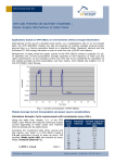
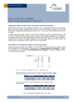
APPLICATION NOTE 205 PTM 230 BATTERY POWERED – Power Supply Alternative to ECO 100 1. INTENTION OF THIS APPLICATION NOTE This Application Note relates to an EnOcean PTM 230 module as a battery-powered electronic radio switch. When using a small Li/MnO2 coin cell like CR2032, the transmitter module has a service life of over 5 years with in excess of 2 Million radio transmissions. 2. PROBLEM According to the User Manual, the PTM 230 needs a short energy pulse of around 3 to 8 ms, supplied by the ECO 100 energy generator (approx 250µWs), to transmit an RF telegram. While the PTM 230 is supplied with energy, it continuously sends telegrams. When battery-powered, the PTM 230 thus additionally requires an external “one-shot” generator which generates exactly one single energy pulse with each push of the button, enough for one telegram. 3. SOLUTION In the simplest case, this “one-shot” generator can be a very inexpensive CMOS component (e.g. CD4538 monostable, quiescent current of only few nA compared with about 250 nA battery self discharge current, see below!) If an additional key control (SW1, SW2) is needed, both can be implemented using a small, inexpensive ultra low power µ-controller (e.g. MSP430F2001). 4. CIRCUIT EXAMPLE FOR “PUSHBUTTON PRESSED” TRANSMITS A TELEGRAM This circuit example shows a single micro pushbutton application. Each time the button is pushed, the circuit transmits an ON (SW1 at Vcc) telegram. A typical application is e.g. automatic stairwell lighting: light is switched on manually and switches off automatically after a specified time. 4.1. Key components RF transmitter module = EnOcean PTM 230 Signal generator = CD4538 µ pushbutton = EVQP0 (>2 mill. switching operations) Battery = CR2032 from Renata (3 V, 235 mAh, -30....+70°C, Li/MnO2, self-discharging rate at 23°C < 1% / year) • 4.2. Energy pulse duration The duration T of the energy pulse must be long enough to allow the transmission of energy for a complete telegram (containing 3 sub telegrams). On the other hand, T should not be unnecessarily long, since excess energy is converted into heat and thus wasted (see User Manual PTM 230). For these reasons, the duration T was chosen to be about 10ms. According to Data Sheet CD4538, this results in the following: © EnOcean | www.enocean.com Subject to modifications | Christian Bach | Sep 2010 | Page 1/ 4 APPLICATION NOTE 205 PTM 230 BATTERY POWERED T = RC = 10 ms = 10MΩ x 1 nF C should be kept as small as possible to avoid wasting energy due to charging (and discharging) of the capacitor. The 1 nF capacitor calculated above assures the transmitting of a complete standard telegram consisting of at least 3 sub telegrams. With increasing or decreasing his value the number of the transmitted (sub) telegrams may be varied. If for example, 2 sub telegrams are enough, 470…680 pF would be also sufficient. During one transmission, peak currents as high as about 15 mA (for few milliseconds only) will be drawn from the power supply. Since a small coin battery alone has a limited ampacity it could be helpful to use a low leakage buffer (SMD) Tantalum or ceramic capacitor of about 47-100 µF in parallel to avoid a long time damage of the battery. Fig. 1: Circuit Example A 4.3 Energy Balance In classic applications, a PTM 230 needs a relatively short energy pulse of approx. <250 µWs to transmit a telegram. Using a typical 2.5 – 3 V supply voltage, this roughly corresponds to a battery draw of 100 µAs. Since the nominal battery capacity is generally provided in Ah, 100µAs equals 100 x 10-6 x 1/3600 Ah = 0.000000028 Ah per telegram. Even a battery capacity of a mere 0.150 Ah (a coin cell CR2032 has > 0.220 Ah) would theoretically mean 1500 x 3600 = 5.4 Million telegrams. Bearing in mind that the energy of a battery cannot be fully drawn for this (only approx. 50%), a single CR2032 coin cell still allows more than 2 Millions telegrams to be transmitted. © EnOcean | www.enocean.com Subject to modifications | Christian Bach | Sep 2010 | Page 2/ 4 APPLICATION NOTE 205 PTM 230 BATTERY POWERED 5. CIRCUIT EXAMPLE FOR “PUSHBUTTON PRESSED/RELEASED” TRANSMITS A TELEGRAM For a separate transmission of the status “button pushed” or “button released”, the polarity of the PTM 230 input voltage must in each case be reversed (PWR1 and PWR2). Via the two coding inputs SW1 and SW2 of the PTM 230, it is possible to program up to four buttons in the data telegram. The required signal combinations can be created using a small micro controller with some SW programming. All SW states plus polarity combinations are listed in the PTM 230 User Manual. Important is that the receiver is able to interpret the different SW and PWR combinations. Headline 4 Text 4 Headline 4 Text 4 Headline 4 Text 4 Fig. 2: Circuit Example B 5.1. Dimensioning It is important for the dimensioning that the individual control signals have the required length, are synchronized (SW with appropriate PWR) and that the PWR polarity pulses do not “overlap” at any time (include delay time). Only then cross currents during polarity reversal by the MOSFETS can be prevented! The SW states must already exist before the energy pulse comes. The micro controller MSP430F2001 was chosen due to its favorable price and low power consumption (100 nA). © EnOcean | www.enocean.com Subject to modifications | Christian Bach | Sep 2010 | Page 3/ 4 APPLICATION NOTE 205 PTM 230 BATTERY POWERED 5.2. Examples of SW and PWR combinations Action S1 closed: SW1=Vcc SW2=open PWR1+ Data 00010000 Status XX11RRRR Action S1 open: SW1=Vcc SW2=open PWR1- Data 00000000 Status XX11RRRR Action S2 closed: SW1=open SW2=Vcc PWR1+ Data 00110000 Status XX11RRRR Action S2 open: SW1=open SW2=Vcc PWR1- Data 00100000 Status XX11RRRR Action S3 closed: SW1=Vcc SW2=Vcc PWR1+ Data 00110001 Status XX11RRRR Action S3 open: SW1=Vcc SW2=Vcc PWR1- Data 00100001 Status XX11RRRR Action S4 closed: SW1=open SW2=open PWR1+ Data 0001xxxx Status XX10RRRR Action S4 open: SW1=open SW2=open PWR1- Data 0000xxxx Status XX10RRRR Fig. 3: PTM 230 input codings (from User Manual) Disclaimer The information provided in this document describes typical features of the EnOcean radio system and should not be misunderstood as specified operating characteristics. No liability is assumed for errors and / or omissions. We reserve the right to make changes without prior notice. For the latest documentation visit the EnOcean website at www.enocean.com. © EnOcean | www.enocean.com Subject to modifications | Christian Bach | Sep 2010 | Page 4/ 4