1
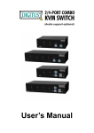
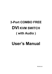
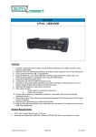
4-Port Pocket
USB KVM Switch with USB 2.0 Hub
Manual
-1-
Index
1. INTRODUCTION............................................................................................. 3
1.1 FEATURES ...................................................................................................... 3
1.2 PHYSICAL DIAGRAM ......................................................................................... 4
1.3 PACKAGE CONTENTS ....................................................................................... 4
2. SPECIFICATIONS .......................................................................................... 5
2.1 ERAL .............................................................................................................. 5
2.2 LED INDICATORS............................................................................................. 6
3. INSTALL THE USB KVM SWITCH ................................................................. 7
3.1 SYSTEM REQUIREMENTS .................................................................................. 7
3.2 HARDWARE INSTALLATION................................................................................. 7
3.3 Notice for Sun Micro System user.................................................................. 7
3.4 POWERING UP THE SYSTEMS ............................................................................ 7
3.5 DRIVER INSTALLATION ...................................................................................... 7
3.6 USING THE OSD PROGRAM .............................................................................. 10
4. SWITCHING THE USB KVM SWITCH............................................................ 13
*AUTO-SWITCH FUNCTION............................................................................... 15
*AUTO-SCAN FUNCTION................................................................................... 15
*Sun Micro System Key Emulation ...................................................................... 17
-2-
1. Introduction
Thank you for purchasing our USB KVM Switch! You now have a high
quality and durability system that can give you the control over multiple
computers/servers from one console (Mouse, Keyboard and Monitor).
1.1 Features
1. Controls 4 computers from a single console (Keyboard/Mouse) over USB
connection using standard USB cables.
2. Supports PS/2 and USB Keyboard/Mouse (Hot-Key function supports
only on PS/2 Keyboard).
3. Fully compliant with the USB 2.0 specification.
4. Supports Windows, Linux, Mac OS9/OSX, SunMicro Solaris 8 (For Sun
Micro users, the external power adaptor is necessary when using the
KVM Switch).
5. Supports 3 USB 2.0 downstream ports.
6. 4 computers can share 3 USB 2.0 Downstream ports.
7. Supports 3 types of switching: hardware push button, Hot-Keys on PS/2
keyboard, and On-Screen-Display (OSD) utility software (for Windows
only).
8. OSD and LED display for easy status monitoring.
9. OSD utility indicates:
1. Power status of connected computer(s).
2. Active host computer.
10. Provide HUB switching in independent method or combination with the
host switching( AutoSwitch mode ).
11. Auto-Scan function (Time interval can be adjusted between 5-20
seconds when the Auto-Scan function is enable).
12. Supports VGA resolutions up to 2048x1536 @ 85HZ.
13. Plug and Play (Windows 98/SE users might need your Windows CD to
install the HID driver for USB Keyboard/Mouse).
-3-
1.2 Physical Diagram
Host LED
HUB
Push Button
AutoScan Button
AutoScan LED C
Hub AutoSwitch LED
1.3 Package Contents
The product you purchased should contain the equipment and
accessories shown as follows:
1. USB KVM Switch.
2. 2 pcs. KVM cable sets, 1,8 m
3. CD with users manual, On-Screen-Display(OSD) utility.
-4-
2. Specifications
2.1 General
Specification
Operating Temperature
5~ 40°C
Humidity
0%~80%RH
Dimensions (LxWxH)
200 x 82 x 44mm
Unit Weight
721g
Number Of Computer Controlled
4
PS/2 Keyboard & Mouse Support
Yes
Keyboard Hot-Key Switching Supported
Yes (By PS/2 Keyboard only)
USB 2.0 Downstream ports
3
Compliant with USB Version
USB 1.0 / USB 1.1 / USB 2.0
Compliant with HID Version
USB HID 1.1, 2.0
Over-Current protection design for USB
Downstream ports
Yes
Power
By Host or External Adaptor (Optional)
Basic Power Consumption
DC 5V
Bus-Power limit current protection
500mA (When external adaptor applied)
Output Voltage
5V
Output Current
2A
OSD (On Screen Display)
Yes (Application Program, Windows only)
DDC, DDC2 monitor
Yes (Max. Resolution: 2048x1536)
Hot Pluggable
Yes (USB & PS/2)
Auto-Scan function
Yes (5 ~20 seconds)
Support Sun Micro Serious
Yes
Support Mac Serous
Yes
Support Linux Serious
Yes
Device driver
No
-5-
2.2 LED Indicators
l Power status LED indicator:
On (Green): The power is connected and the device is ready to work.
Off: No power is connected.
l
USB 2.0 Downstream Ports LED Indicator:
ON (Green): USB ports are ready to work.
Off: USB ports are in over-current condition or are not ready to work.
Note:
If over-current situation happens for certain USB downstream ports, the
corresponding USB 2.0 indicator will turn OFF to indicate that these ports
is not working now. When over-current situation is solved, the USB
indicator will turn ON again.
l
Auto-Switch LED Indicator:
ON: Auto Switch mode is on.
Off(Green): Auto Switch mode is off.
l
Auto-Scan LED Indicator:
Off: Auto Scan mode is off.
ON (Green): Auto Scan mode is on.
l
PC Host LED Indicator (Red):
ON: Indicates which Host PC is selected.
l
HUB LED Indicator (Green):
ON: Indicates which Host connect with the three USB 2.0 downstream
HUB ports.
-6-
3. Install USB KVM Switch
3.1 System Requirements
A PC with 1 spare USB port and 1 VGA port.
Windows 98 or later, Mac OS9/OSX, Solaris 8 (SUN BLADE 100), Linux
Kernel 2.3 or later.
3.2 Hardware Installation
Make sure that the USB port of your computer is enabled and working
properly.
Connect the USB cable Type-A end to the USB port of your computer,
and the USB cable Type-B end to the any available upstream on USB
KVM Switch.
Connect the VGA male-to-female cable between the video port of your
computer and video port that corresponds to the USB port you selected in
step 2.
Repeat steps 1-3 for any other computers you are connecting up. Up to 4
computers can be connected at the same time.
Plug the power adaptor cable into the USB KVM Switch (optional).
3.3 Notice for Sun Micro System user
Since some Sun Micro system will detect the monitor information, if
system fail to get information from the Monitor, then you won’
t get any
screen came out. So for safety, “YOU MUST SWITCH USB KVM
SWITCH TO THE SUN MICRO SYSTEM”before you power on the Sun
Micro System. After you seeing the screen from the Sun Micro System,
then you can switch to any other Host. If you have multiple Sun Micro
systems, then you have to repeat this procedure one by one.
3.4 Powering up USB KVM Switch
USB KVM Switch supports USB plug & play technology. All the
components can be added and removed at any time without the need to
shut the unit down.
3.5 Driver Installation (Windows 98/SE only)
After you connect USB KVM Switch to your PC, Win 98 will automatically
detect the device and prompt for the driver installation. Please install USB
KVM Switch by following the instruction from Step A-E. Please have your
Windows 98 CD ready.
-7-
A. Press “Next”to
Continue.
(Ref. Fig. A)
Fig. A
B. Tick “Search for the
best driver for your
device”and press “Next”
to continue.
(Ref. Fig. B).
Fig. B
C. Please insert the
“Windows 98”CD into
your CD-ROM drive. Tick
“CD-Rom drive”and press
“Next”to continue.
(Ref. Fig. C)
Fig. C
-8-
D. Press “Next”to start
the installation process.
(Ref. Fig. D)
Fig. D
D1. Sometimes Windows
cannot locate the
necessary driver
automatically. So you
need to choose “Browse”
to specify the location of
the driver on your
“Windows 98”CD
manually. *
(Ref. Fig. D1)
Fig. D1
* The driver might be located in a different directory from the figure
above.
-9-
D2. Press “OK”to
continue
(Ref. Fig. D2)
Fig. D2
E. Press “Finish”and
Windows has finished
installing the USB Human
Interface Device driver for
PS/2 keyboard & mouse.
(Ref. Fig. E)
Fig. E
3.6 Using the OSD program
Fig. F
- 10 -
There are four different statuses:
a. “No PCs Found”means that USB KVM Switch cannot acquire the PC
status. This is either the PC did not connect or is powered off. (Ref.
Fig. G)
Fig. G
The “Large RED colour 4”and “Small GREEN colour 2”means that 2
PCs are connected to Port 1 and Port 4 of your USB KVM Switch
respectively, and you have switched to Port 4 already. So the OSD
program displayed a “PC 4 On”underneath. You can click “Small GREEN
colour 2”to switch to this available host. (Ref. Fig. H)
Fig. H
The “Large RED colour 4”and “Small GREEN colour 1, 2, 3”means that
four PCs are connected to Port 1 and Port 4 of your USB KVM Switch
respectively, and you have switched to Port 4 already. So the OSD
program displayed a “PC 4 On”underneath. You can click Small GREEN
colour 1, 2 or 3”to switch to a certain available host. (Ref. Fig. I)
Fig. I
- 11 -
1
2
3
Fig. J
1. When user click “Hide”button, OSD program window will hide in
Taskbar.
2. When user click “Close”button, OSD program will exit.
3. If OSD program hide in Taskbar, user can use mouse right button to
show or exit program.
- 12 -
4. Switching the USB KVM Switch
USB KVM Switch supports 3 methods to switch between computers:
Push button, Hot Keys and OSD. Due to refresh of the video and
re-synchronization of the mouse and keyboard signal, it will take 1-3
seconds configure time after each switching. This is the normal operation
that ensures the proper synchronization is established.
Note:
The drivers for most USB devices (Mass Storage device, CCD Cameras,
Scanners, Card Reader, Printers, e.g.) are required to be shut down or
follow the “Safely Remove”command provided in Windows before you
disconnect the device, or else the system might be hanged. When you
switch computers with the Port Selection Switch, it is the equivalent of
disconnecting the device. Therefore, if you have peripheral devices (other
than a second keyboard and mouse) connected to these ports, you must
be sure to shut down or safely remove the USB driver for them before
switching computers.
1. Manual Switch by pushbutton:
You can switch to any other available active USB host connection by
simply push the appropriate switch button on USB KVM Switch. The LED
will be lit to indicate which port is currently selected.
2. Two Steps Hot Key Switch by keyboard:
You can switch to any available active USB host connection by using the
three steps Hot Key directly, instead of manually select by pushbutton. To
send commands to USB KVM Switch,
must be pressed twice
( Step1 ). Then you can press [1] to [4] (Step 2) to switch between ports.
(Support PS/2 Keyboard only)
- 13 -
*After invoking the Hot Key function with the
you must
key in the corresponding active key (Step 2) within 3 seconds for
each key press.
(The Scroll LED will start blinking and wait for the Step 2 hotkey, after
pressing any key or over 3 seconds, the keyboard LED will back to the
original status.)
Three Steps Hot Key definition table
Step 1
Step2
Action
USB HUB Auto-Switch mode
Switches access to the computer which connecting
to host1
Switches access to the computer which connecting
to host2
Switches access to the computer which connecting
to host3
Switches access to the computer which connecting
to host4
Switch the HUB to host 1
Switch the HUB to host 2
Switch the HUB to host 3
Switch the HUB to host 4
*
No Scroll Key
Need
*
*
*
AutoScan time interval is 5 seconds
(Available only when Auto-Scan function is ON)
AutoScan time interval is 10 seconds
(Available only when Auto-Scan function is ON)
AutoScan time interval is 15 seconds
(Available only when Auto-Scan function is ON)
AutoScan time interval is 20 seconds
(Available only when Auto-Scan function is ON)
* Notice : To adjust the interval time for AutoScan, you do not need to
press the SCROLL key, and this can be used only by normal number
key.
- 14 -
3. On-Screen-Display (OSD) Switch (Windows only):
You may also use the OSD utility software from the enclosed CD to
switch between computers.
* Auto-Switch Function:
When Auto-Switch mode is ON:
When you enable the AutoSwitch mode will cause the USB KVM Switch
to switch the HUB with the host together when you switch the host, that
means host and HUB will switch together, it could be by hotkey, push
button. This is convenient for you to let the USB device always follow the
host.
There are two ways to turn the HUB Auto-Switch mode ON :
A). By hot key [Scroll+Scroll][H] : please be reference the hotkey table in
page 14.
B). Press any host push button continually for 2 seconds when the
Auto-Switch mode is OFF. ( The Auto-Switch LED will be ON ).
When Auto-Switch mode is OFF:
You must switch the hub to the new target host by hotkey.
There are two ways to turn the HUB Auto-Switch mode OFF :
A). By hot key [Scroll+Scroll][H] : please reference the hotkey table in
page 14.
B). Press any host push button continually for 2 seconds when the
Auto-Switch mode in ON. ( The AutoSwitch LED will be OFF)..
* Auto-Scan Function:
When you press the Auto-Scan button, USB KVM Switch switches cycles
through all the ports and displays them on the monitor. Each port is
displayed for 5,10,15,20 seconds before switching to the next. You can
press the normal numeric key 1,2,3,4 to adjust the interval time(Please
reference the hotkey table in page 14). If you press the Auto-Scan button
again, the monitor screen will jump back to the port that it was started.
Note:
The mouse and keyboard will have no effect in this mode. This is
necessary to prevent errors such as erratic movement and wrong
characters to display when using the mouse or keyboard in accident.
- 15 -
Auto-Scan Interval timer
[n]
*(Available only when Auto-Scan function is ON)
You can change the Auto-Scan interval by pressing the appropriate
number key or the number pad keys.
[jw1]
n
[1]
[2]
[3]
[4]
[5]
[6]
[7]
[8]
[9]
[0]
Scan Interval
5 sec.
10 sec.
15 sec.
20sec.
25sec.
30sec.
35sec.
40sec.
45sec.
50sec.
- 16 -
* Sun Micro System Function Key Emulation:
There are 16 special functions on the Sun Micro system keyboard, the
USB KVM Switch can emulate these function keys via the PS/2 keyboard ( it
won’
t work on the USB keyboard ). Here is the mapping table for these
function operation. To active these emulation on the PS/2 keyboard, you have
to press the LEFT Window KEY first ( this key usually is located between the
left [Ctrl] and left [Alt]), then choice the second relative key.
Sun Micro System
Function Key
Stop
PS/2 Keyboard
Props
L_Win & L_Ctrl
Compose
L_Win & L_Shift
Front
L_Win & F1
Open
L_Win & F2
Find
L_Win & F3
Again
L_Win & F4
Undo
L_Win & F5
Copy
L_Win & F6
Paste
L_Win & F7
Cut
L_Win & F8
Help
L_Win & F11
Power
L_Win & F12
Mute
L_Win & 1
Volume Down
L_Win & 2
Volume UP
L_Win & 3
L_Win & L_Alt
- 17 -
FCC Statement
This device generates and uses radio frequency and may cause interference to radio and television reception if not
installed and used properly. This has been tested and found to comply with the limits of a Class B computing device
in accordance with the specifications in Part 15 of the FCC Rules. These specifications are designed to provide
reasonable protection against such interference in a residential installation. However, there is no guarantee that
interference will not occur in a particular installation. If this device does cause harmful interference to radio or
television reception, which can be determined by plugging the device in and out, the user can try to correct the
interference by one or more of the following measures:
l
Reorient or relocate the receiving antenna.
l
Increase the separation between the device and receiver.
l
Connect the computer into an outlet on a circuit different from that to which the receiver is connected.
l
Consult the dealer or an experienced radio/TV technician for help.
Safety Information:
This device may only be operated in enclosed, dry rooms. To prevent the risk of fire or electrical shock, the device
must be protected from moisture. In the event of a defective power plug, please contact an authorized retailer. In the
event of damage to the housing or the power plug, do not operate. Do not open the device. Repairs may only be
performed by an authorized retailer.
Note:
In the event of incorrect installation and improper use in a residential area, the device may cause disruptions in radio
devices and other electronic devices. Proper use means that the device is operated with shielded connector cables
as far as possible, for network products also with shielded cables of category 5e and higher. The device was tested
and lies within the limits for computer accessories of class A according to the requirements of EN 55022.
Warning:
This is a class A device. This device can cause radio interference in residential areas; in this case, the operator may
be required to perform and bear the costs for appropriate measures.
Conformity Declaration:
The device fulfils the EMC requirements of EN 55022 class A for ITE and EN 55024. Devices with external or built-in
power supply also fulfil the requirements of EN 61000-3-2 and EN 61000-3-3. The basic protection requirements of
the “EMC Directive”89/336/EEC are therefore fulfilled. The CE conformity has been certified. The corresponding
declarations are available from the manufacturer.
Trademarks:
All company, brand and product names used in these instructions are trademarks or registered marks of the
corresponding companies.
- 18 -