1
UM1601
User manual
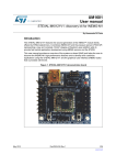
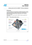
STEVAL-MKI121V1: discovery kit for INEMO-M1
Introduction
The STEVAL-MKI121V1 features the second generation of the iNEMO™ module family
offered by STMicroelectronics. It combines INEMO-M1 and the pressure sensor LPS331AP,
representing a new and complete 10-DoF (degree-of-freedom) open platform able to
provide fast inertial application development using MEMS sensors and the STM32.
This user manual provides an overview of the system-on-board (SoB) and helps the user to
discover the INEMO-M1 high-performance features and to develop and customize
applications using the STEVAL-MKI121V1 and the graphical user interface (iNEMO suite)
that is provided with the kit.
Figure 1. STEVAL-MKI121V1 evaluation board
February 2015
DocID024165 Rev 2
1/33
www.st.com
33
Contents
UM1601
Contents
1
2
Overview . . . . . . . . . . . . . . . . . . . . . . . . . . . . . . . . . . . . . . . . . . . . . . . . . . 3
1.1
Features . . . . . . . . . . . . . . . . . . . . . . . . . . . . . . . . . . . . . . . . . . . . . . . . . . . 3
1.2
Demonstration software . . . . . . . . . . . . . . . . . . . . . . . . . . . . . . . . . . . . . . . 3
Hardware layout and configuration . . . . . . . . . . . . . . . . . . . . . . . . . . . . . 4
2.1
3
Power supply and power selection . . . . . . . . . . . . . . . . . . . . . . . . . . . . . . . 5
2.1.1
USB supply source . . . . . . . . . . . . . . . . . . . . . . . . . . . . . . . . . . . . . . . . . 5
2.1.2
VEXT supply source . . . . . . . . . . . . . . . . . . . . . . . . . . . . . . . . . . . . . . . . 6
2.1.3
D_VDD supply source . . . . . . . . . . . . . . . . . . . . . . . . . . . . . . . . . . . . . . . 6
2.2
INEMO-M1 . . . . . . . . . . . . . . . . . . . . . . . . . . . . . . . . . . . . . . . . . . . . . . . . . 6
2.3
LPS331AP MEMS pressure sensor . . . . . . . . . . . . . . . . . . . . . . . . . . . . . . 8
2.4
Serial wire debug (SWD) connector . . . . . . . . . . . . . . . . . . . . . . . . . . . . . 10
2.5
Pushbuttons . . . . . . . . . . . . . . . . . . . . . . . . . . . . . . . . . . . . . . . . . . . . . . . 10
2.6
LEDs . . . . . . . . . . . . . . . . . . . . . . . . . . . . . . . . . . . . . . . . . . . . . . . . . . . . 10
2.7
Extension connectors . . . . . . . . . . . . . . . . . . . . . . . . . . . . . . . . . . . . . . . . .11
2.8
USB . . . . . . . . . . . . . . . . . . . . . . . . . . . . . . . . . . . . . . . . . . . . . . . . . . . . . 14
2.9
Jumpers . . . . . . . . . . . . . . . . . . . . . . . . . . . . . . . . . . . . . . . . . . . . . . . . . . 15
Getting started with iNEMO suite . . . . . . . . . . . . . . . . . . . . . . . . . . . . . 16
3.1
iNEMO suite . . . . . . . . . . . . . . . . . . . . . . . . . . . . . . . . . . . . . . . . . . . . . . . 17
3.1.1
iNEMO suite main window . . . . . . . . . . . . . . . . . . . . . . . . . . . . . . . . . . . 19
3.1.2
Connecting iNEMO . . . . . . . . . . . . . . . . . . . . . . . . . . . . . . . . . . . . . . . . 20
3.1.3
Acquisition settings . . . . . . . . . . . . . . . . . . . . . . . . . . . . . . . . . . . . . . . . 21
3.1.4
Starting the acquisition and visibility of data . . . . . . . . . . . . . . . . . . . . . 23
3.1.5
Starting the AHRS algorithm and settings . . . . . . . . . . . . . . . . . . . . . . . 23
3.1.6
AHRS 3D demo . . . . . . . . . . . . . . . . . . . . . . . . . . . . . . . . . . . . . . . . . . . 24
3.1.7
3D view alignment . . . . . . . . . . . . . . . . . . . . . . . . . . . . . . . . . . . . . . . . . 25
3.1.8
Compass demo . . . . . . . . . . . . . . . . . . . . . . . . . . . . . . . . . . . . . . . . . . . 26
Appendix A Schematics . . . . . . . . . . . . . . . . . . . . . . . . . . . . . . . . . . . . . . . . . . . . . 27
4
2/33
Revision history . . . . . . . . . . . . . . . . . . . . . . . . . . . . . . . . . . . . . . . . . . . 32
DocID024165 Rev 2
UM1601
Overview
1
Overview
1.1
Features
•
1.2
Two power supply options
–
through the USB connector (5 V), or
–
from an external supply voltage (3.6 V - 6 V VEXT or 2.4 V - 3.6 V D_VDD)
•
INEMO-M1: 9-axis SoB, 13x13x2 mm compact design
•
LPS331AP: MEMS pressure sensor 260-1260 mbar absolute digital output barometer
•
Extension header for INEMO-M1 I/Os for quick connections to prototype the board and
for easy probing
•
SWD connector for programming and debugging
•
Two push buttons (reset and user)
•
Two LEDs (user LED, power-on LED)
•
Mini-B USB connector
Demonstration software
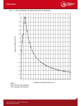
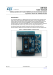
To facilitate user development and analysis of the sensor data, the STEVAL-MKI121V1
demonstration kit includes a graphical user interface (GUI), iNEMO suite, to display sensor
outputs, the compass application, AHRS 3D demo cube(a), as well as a firmware library for
easy development of customized applications and a package for a DFU (Device Firmware
Upgrade).
The iNEMO suite application allows the user to also work with the previous iNEMO V1 and
iNEMO V2 platforms. At the startup of the application, the kit selector window appears, in
order to choose the platform used (select STEVAL-MKI121V1 in this case). For more details
on getting started with the iNEMO suite, please refer to Section 3.The latest version of the
firmware package and PC GUI can be downloaded from the STEVAL-MKI121V1 product
page on www.st.com.
Figure 2. iNEMO suite GUI
a. The STEVAL-MKI121V1 runs the AHRS 3D demo cube, the AHRS algorithm library is available in iNEMO
Suite package in compiled format.
DocID024165 Rev 2
3/33
33
Hardware layout and configuration
2
UM1601
Hardware layout and configuration
The STEVAL-MKI121V1 discovery board has been designed to evaluate the INEMO-M1
features.
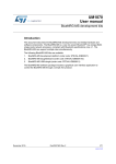
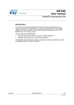
Figure 3 illustrates the hardware block diagram of the device.
Figure 3. STEVAL-MKI121V1 block diagram
60'
/'38
3RZHUPDQDJHPHQW
/36$3
'LJLWDOSUHVVXUH
VHQVRU
9ROWDJH
UHJXODWRU
'B9''
,&
,1(020
8VHU/('
EXWWRQ
6:'
*3,2
'HEXJ
*3,2
([WHQVLRQ
FRQQHFWRUV
86%
0LQL86%W\SH
%FRQQHFWRU
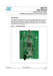
Figure 4 illustrates the top view of the layout and Figure 5 shows the bottom view.
Figure 4. Top view - layout description
4/33
DocID024165 Rev 2
UM1601
Hardware layout and configuration
Figure 5. Bottom view - layout description
2.1
Power supply and power selection
The STEVAL-MKI121V1 can be powered through a USB connector or an external power
supply voltage up to 6 V DC as follows:
2.1.1
•
5 V DC power from type B mini USB connector
•
3.6 to 6 V DC power from VEXT (pin1 of the J15 extension connector)
•
2.4 to 3.6 V DC power from D_VDD (pin1 of the J12, J13 or J14 extension connector)(b)
USB supply source
If the STEVAL-MKI121V1 is supplied through the USB connector, one of two options can be
selected to regulate the voltage:
•
INEMO-M1 internal voltage regulator
•
STEVAL-MKI121V1 (LSD3985PU33R) voltage regulator
The voltage regulator is selected using J2 and J3 according to Table 1. The LED D13 is
turned on if the board is powered correctly.
b. The VEXT pin has to be left floating
DocID024165 Rev 2
5/33
33
Hardware layout and configuration
UM1601
Table 1. Power selection options
Regulator
2.1.2
J2 jumper configuration
J3 jumper configuration
STEVAL-MKI121V1
(LSD3985PU33R) voltage regulator
ON
NEMO-M1 internal voltage regulator
x
VEXT supply source
The STEVAL-MKI121V1 is powered by VEXT, connecting the voltage source to pin 1 of the
J15 extension connector.
The input voltage value shall be in the range 3.6 - 6 V and it is regulated in this case by the
internal INEMO-M1 voltage regulator.
2.1.3
D_VDD supply source
The STEVAL-MKI121V1 is powered by D_VDD, connecting the voltage source to pin1 of the
J12 or J13 or J14 extension connector.
The input voltage value shall be in the range 2.4 - 3.6 V. In this case the INEMO-M1 internal
voltage regulator is bypassed, so the VEXT pin has to be left floating.
2.2
INEMO-M1
The INEMO-M1 is the smallest sensor fusion system-on-board (SoB) of the iNEMO module
family.
The INEMO-M1 is a 9-degree-of-freedom system-on-board (SoB), combining the latest
advances in ST MEMS-based technology with the powerful computational core (ARM®
Cortex™-M3) of the STM32 family. The INEMO-M1 platform has been designed following
specific guidelines in order to have a modular solution based on the principles of
miniaturization, low power consumption and cost effectiveness, obtaining a solution having
the best trade-off between performance and flexibility of the system to cover a wide range of
applications.
6/33
DocID024165 Rev 2
UM1601
Hardware layout and configuration
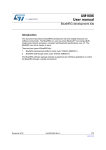
Figure 6. INEMO-M1
This SOB provides the following benefits.
•
The INEMO-M1 operates from a 2.4 V - 3.6 V power supply voltage range. Additionally,
the internal voltage regulator LDS3985M33R enables the module to be powered by an
external voltage from 3.6 up to 6 V, correctly supplying the devices on-board and also
supplying external ICs
•
The INEMO-M1 architecture embeds the:
–
STM32F103REY6: WLCSP package, high density performance line ARM®
Cortex™-M3 based 32-bit MCU
–
LSM303DLHC: 6-axis geomagnetic module, ±2g, ±4g, ±8g, ±16g linear
acceleration programmable full scale, and from ±1.3 Gauss to ±8.1 Gauss
magnetic programmable field full scale, I2C digital output
–
L3GD20: 3-axis digital gyroscope (roll, pitch, yaw), 16-bit data output, ±250°/s,
±500°/s, ±2000°/s selectable full scale
–
LDS3985M33R: ultra-low drop-low noise BiCMOS 300 mA voltage regulator
•
The INEMO-M1 has been designed to exploit a wide range of peripherals (CAN,
USART, SPI and I2C, full-speed USB 2.0) supported by the STM32F103REY6, in order
to have the maximum flexibility in communication. Thanks to this full range of
communication peripherals and its extremely compact design, the INEMO-M1 can be
directly integrated in a broad variety of advanced motion-based platforms in several
application segments, resulting in enhanced performance of the platform as the
system’s capabilities are accessible within the application.
•
Free ADC channels for external inputs
•
Low-power modes: power-down/sleep
•
In-system ceramic resonator
•
In-application programming (IAP) interfaces for firmware upgrades
•
Compact design: 13 x 13 x 2 mm
For further information, please consult the INEMO-M1 datasheet and the STM32 reference
and Flash programming manuals which are available from STMicroelectronics at
www.st.com.
DocID024165 Rev 2
7/33
33
Hardware layout and configuration
UM1601
Figure 7. INEMO-M1 functional block diagram
2.3
LPS331AP MEMS pressure sensor
The LPS331AP is an ultra-compact absolute piezoresistive pressure sensor housed in an
HCLGA package.
The device includes a monolithic sensing element and an IC interface able to take the
information from the sensing element and to provide a digital signal to the external world.
The sensing element consists of a suspended membrane inside a single mono-silicon
substrate. It is capable of detecting pressure and is manufactured using a dedicated
process (VENSENS) developed by ST.
The STEVAL-MKI121V1 board uses an I2C communication (I2C1 on pin 12 and pin 13 of
INEMO-M1) and the LPS331AP slave address is set to 0xBA. The LPS331AP features two
fully programmable interrupt sources (INT1 and INT2) which may be configured to trigger
different pressure events. In the STEVAL-MKI121V1, only the INT1 interrupt source is
connected to the INEMO-M1 through Press_INT (pin 7 of INEMO-M1). The device may also
be configured to generate, through the interrupt pins, a data ready signal (Drdy), which
indicates when new measured data is available, therefore simplifying data synchronization
in digital systems. The connection between the LPS331AP and the INEMO-M1 is shown in
Figure 8.
Note:
8/33
I2C1 and INT1 (Press_INT) can be disconnected from the pressure sensor and
reconfigured for other purposes, simply by removing dedicated resistors as described in
Table 3.
DocID024165 Rev 2
UM1601
Hardware layout and configuration
Figure 8. Pressure sensor block diagram
DocID024165 Rev 2
9/33
33
Hardware layout and configuration
2.4
UM1601
Serial wire debug (SWD) connector
The SWD connector allows program loading and debugging of the STM32 inside INEMOM1 using a SWD dongle (like ST-LINK/V2) through a dedicated JTAG_SWD adapter board.
A specific driver needs to be installed on the user’s PC for communication with the SWD
dongle.
Figure 9. SWD connector (J11) and schematic
2.5
Pushbuttons
•
SW1: reset pushbutton connected to nRESET is used to reset the INEMO-M1
•
SW2: user button connected to pin 16 of INEMO-M1
Note:
The user button can be disconnected from SW2 and reconfigured for other purposes simply
by removing the dedicated resistor as described in Table 3.
2.6
LEDs
Note:
10/33
•
D4: Blue LED is a user LED connected to the I/O pin 26 of INEMO-M1
•
D13: Red LED indicates that the board is powered.
The user LED can be disconnected from D4 and reconfigured for other purposes simply by
removing the dedicated resistor as described in Table 3.
DocID024165 Rev 2
UM1601
2.7
Hardware layout and configuration
Extension connectors
Four 7-pin male connectors J12, J13, J14 and J15 can be used to connect a user’s
daughterboard to facilitate the development of applications.
Each pin on the connectors can be utilized by the user’s daughterboard, a lot of these are
free I/Os and others can be used after disconnecting them from the corresponding
functional block on the STEVAL-MKI121V1 board. Please refer to Table 2 and Table 3.
Table 2. INEMO-M1 pin description versus board function
INEMOM1 pin Description
#
Basic
Function
Remap
MCU
pin
name
STEVALMKI121V1 Free Pin # Pin # Pin # Pin #
I/O assign- I/O of J12 of J13 of J14 of J15
ment
1
VDD (2.4 3.6 V)(1)
2
BOOT0
BOOT
0
BOOT0
3
nRESET
NRST
Reset
button
D_VDD
1
1
2
2
GPIO_PA3
USART2_RX /
TIM5_CH4 /
ADC123_IN3 /
TIM2_CH4
PA3
4
5
GPIO_PA2
USART2_TX /
TIM5_CH3 /
ADC123_IN2 /
TIM2_CH3
PA2
5
6
GND
4
7
GPIO_PA0
WKUP /
USART2_CTS
/ ADC123_IN0
/ TIM2_CH1_
ETR /
TIM5_CH1 /
TIM8_ETR
PA0WKUP
1
GND
7
LPS331AP(
Press_INT)
6
7
7
(2)
8
USART1_CTS
/ USBDM /
GPIO_PA11
CAN_RX /
TIM1_CH4
PA11
6
9
USART1_RTS
/ USBDP /
GPIO_PA12
CAN_TX /
TIM1_ETR
PA12
5
10
GPIO_PB6
I2C1_SCL /
TIM4_CH1
USART1_
PB6
TX
4
11
GPIO_PB7
I2C1_SDA /
TIM4_CH2
USART1_
PB7
RX
3
DocID024165 Rev 2
11/33
33
Hardware layout and configuration
UM1601
Table 2. INEMO-M1 pin description versus board function (continued)
INEMOM1 pin Description
#
Basic
Function
Remap
MCU
pin
name
STEVALMKI121V1 Free Pin # Pin # Pin # Pin #
I/O assign- I/O of J12 of J13 of J14 of J15
ment
12
GPIO_PB9
TIM4_CH4
I2C1_SDA
PB9
/ CAN_TX
LPS331AP
(I2C1)(2)
6
13
GPIO_PB8
TIM4_CH3
I2C1_SCL
PB8
/ CAN_RX
LPS331AP
(I2C1)(2)
5
14
GND
GND
7
7
7
15
GND
GND
7
7
7
16
GPIO_PA10
USART1_RX /
TIM1_CH3
17
JTDO
JTDO
18
GPIO_PA9
USART1_TX /
TIM1_CH2
19
JTMSSWDIO
JTMS-SWDIO
20
JTCKSWCLK
JTCK-SWCLK
21
VEXT
(3.6 - 6 V)(3)
PA10
PB3 /
TRACES
WO /
PB3
TIM2_
CH2 /
SPI1_SCK
User Button
(Push_
Button)(2)
7
SWD
(SWO)
4
PA9
USB_EN(2)
GPIO_
PA13
PA13
SWD
(SWDIO)
3
GPIO_
PA14
PA14
SWD
(SWCLK)
2
V_EXT
1
6
22
GPIO_PA4
SPI1_NSS /
USART2_CK /
DAC_OUT1 /
ADC12_IN4
23
GPIO_PA5
SPI1_SCK /
DAC_OUT2 /
ADC12_IN5
GPIO_PA6
SPI1_MISO /
TIM8_BKIN /
ADC12_IN6 /
TIM3_CH1
TIM1_
BKIN
PA6
4
GPIO_PA7
SPI1_MOSI /
TIM8_CH1N /
ADC12_IN7 /
TIM3_CH2
TIM1_
CH1N
PA7
5
GPIO_PA1
USART2_RTS
/ ADC123_IN1
/ TIM5_CH2 /
TIM2_CH2
24
25
26
12/33
PA4
2
PA5
3
PA1
USER_
LED(2)
DocID024165 Rev 2
3
UM1601
Hardware layout and configuration
Table 2. INEMO-M1 pin description versus board function (continued)
INEMOM1 pin Description
#
Basic
Function
Remap
MCU
pin
name
STEVALMKI121V1 Free Pin # Pin # Pin # Pin #
I/O assign- I/O of J12 of J13 of J14 of J15
ment
27
VDD
(2.4 3.6 V)(1)
D_VDD
28
GND
GND
1
1
1
7
7
7
1. When using an external regulated supply voltage, these pins are input supply pins with voltage in the range 2.4 V - 3.6 V.
When using the internal voltage regulator, these pins are @3.3 V (output) and can be used to supply other ICs.
2. Can be reconfigured by the user by removing the related resistor, please refer to Table 3.
3. When using an external regulated supply voltage, this pin shall be left floating. When using the internal voltage regulator,
this pin is used as the supply input in the range 3.6 V- 6 V.
Table 3. Functional block disconnection on STEVAL-MKI121V1
INEMO-M1 pin number
STEVAL-MKI121V1 I/O assignment
How to disconnect from functional block
on STEVAL-MKI121V1 board
7
Press_INT
Remove R41
12
I2C1_SDA
Remove R37
13
I2C1_SCL
Remove R34
16
Push_Button
Remove R40
18
USB_EN
Remove R39
26
USER_LED
Remove R42
DocID024165 Rev 2
13/33
33
Hardware layout and configuration
2.8
UM1601
USB
The STEVAL-MKI121V1 is provided with USB 2.0 compliant full-speed communication via a
USB type mini-B receptacle connector (CN1), with dedicated EMI filter and line termination
through the USBUF02W6 (U8). Pin 18 of the INEMO-M1 is used for the software
connection/disconnection of the USB cable. The MCU pins are configured in output pushpull mode: when high, the USB communication is enabled; when low, it is disabled.
Connector and hardware connections are shown in Figure 10.
Figure 10. USB mini-B connector (CN1) and schematic
14/33
DocID024165 Rev 2
UM1601
2.9
Hardware layout and configuration
Jumpers
The details of the jumper settings are described in Table 4.
Table 4. J1, J2, J3 settings
Jumper
Description
BOOT0 is connected to D_VDD power when J1 is set as shown below.
System memory is selected as boot space
J1
BOOT0 is connected to GND when J1 is set as shown below.
Main Flash memory is selected as boot space
USB_5V is connected to VREG_LDS when J2 is set as shown below. The input
voltage is regulated to 3.3 V by LDS3985PU33R and J3 has to be on to power the
INEMO-M1 module.
J2
USB_5V is connected to V_EXT when J2 is set as shown below. The input voltage is
regulated internally by the INEMO-M1 module
J3
Jumper on: D_VDD is connected to 3.3 V, regulated by the LDS3985PU33R regulator
Jumper off: D_VDD is not connected to 3.3 V. It can be regulated by the INEMO-M1
internal regulator or it can be the voltage source coming from pin1 of the J12 or J13 or
J14 extension connector.
DocID024165 Rev 2
15/33
33
Getting started with iNEMO suite
3
UM1601
Getting started with iNEMO suite
The installation of the graphical user interface (GUI) requires the following two steps:
1.
Install the PC software delivered with the demonstration kit
2.
Install the virtual COM driver needed to use the board
PC system requirement
•
Microsoft Windows XP® Service Pack 2, or higher
•
Microsoft.NET Framework 2.0 (or higher)
PC software installation
To install the iNEMO suite, run the setup file and follow the instructions.
Note:
The latest setup file is available on www.st.com.
Virtual Com driver installation
To install the virtual COM driver, plug the iNEMO board into a free USB port, an icon should
appear in the “Notify Bar”. Wait for the “Hardware Update Wizard” window and follow the
instructions:
–
Install from a list or specific location (Advanced)
–
Browse C:\Program Files\STMicroelectronics\iNEMO Suite\driver inemo and
choose x64 or x86 folder according to your system.
Once the installation has finished, a COM port number is assigned to the ST virtual COM
driver (Figure 11). This number is required to correctly run the iNEMO GUI as outlined in the
steps in 3.1: iNEMO suite.
16/33
DocID024165 Rev 2
UM1601
Getting started with iNEMO suite
Figure 11. How to see the STEVAL-MKI121V1 COM port number
3.1
iNEMO suite
The iNEMO suite application allows the user to also work with the iNEMO V1 and iNEMO
V2 platform. At the startup of the application, the kit selector window appears in order to
choose the platform to be used (Figure 12).
For the STEVAL-MKI121V1 the iNEMO suite application also has a TCP/IP server for
external/remote demo applications. When the server starts, in the log bar a message shows
the availability of the server. Each client may be connected to the server on port
31001(default) to receive data from the device through the iNEMO suite (server).
Every time a client connects to the server, the log bar shows the IP address of the client that
just connected.
Each demo (client) can elaborate and show these data. (The structure of the data sample
sent to all clients is FrameData_t defined in the iNEMOM1_SDK.h file).
The TCP/IP server may be enabled/disabled from the Tools->Communication->Settings
menu (its state is shown on the status bar). From this dialog box, the user can change the
communication port (default 31001). Pay close attention to this information in order to avoid
a communication block from an installed firewall.
DocID024165 Rev 2
17/33
33
Getting started with iNEMO suite
UM1601
To run the iNEMO suite:
1.
Click on Start > All Programs > STMicroelectronics > iNEMO Suite > iNEMO Suite
Application
2.
Launch the iNEMO software tool program (Goldfish icon)
3.
The “Kit Selector” window appears (Figure 12). Select STEVAL-MKI121V1.
4.
Check that the serial port number is correct (see Figure 11). Otherwise click the refresh
button and choose the right COM port.
It is preferable to connect the iNEMO board to a free USB port before launching the GUI. In
this way, the GUI directly finds the COM port into which the board is plugged.
To change the COM port, press the “New” button on the toolbar (Figure 15) or from the
menu File/New and the kit selector dialog window appears.
Figure 12. Kit selector window
18/33
DocID024165 Rev 2
UM1601
3.1.1
Getting started with iNEMO suite
iNEMO suite main window
The main window contains the following sections referenced by the corresponding numbers
in Figure 13:
1.
Sensor selector which allows the user to move to a different sensor data view
2.
Toolbar for data acquisition setting, to set frequency, acquisition mode, etc.
3.
Toolbar for graphic management helps the user to explore the graphic window. It allows
zooming in on the graph, enabling the cursors, saving data, and so on
4.
Status bar shows the acquisition info
5.
Log window
6.
Default menu bar
7.
Graph where the data are plotted
Figure 13. iNEMO suite main window
DocID024165 Rev 2
19/33
33
Getting started with iNEMO suite
3.1.2
UM1601
Connecting iNEMO
Before starting the acquisition of data, it is necessary to open the connection between
iNEMO and the PC. It is preferable to connect the iNEMO board to a free USB port before
launching the GUI. In this way, the GUI directly finds the COM port into which the board is
plugged.
The bottom part of the GUI main window shows the COM port number, see Figure 14.
Figure 14. Selected COM port number
The user must check that the COM port number is the same as the one shown in the device
manager (Figure 11).
If the COM number is different, it is necessary to set the right number. By clicking the new
data file icon (Figure 15), the kit selector window appears and it is possible to select the
COM port number as in Figure 12.
Figure 15. New data file icon
20/33
DocID024165 Rev 2
UM1601
Getting started with iNEMO suite
When the correct COM number is set, click on the connect icon to open the communication
and, in the log window, a connection message appears (Figure 16).
Figure 16. How to open the connection
3.1.3
Acquisition settings
Before starting the acquisition it is possible to modify the acquisition setting (Figure 17):
•
Sensor output:
–
•
•
Enable/disable the output of a sensor
Acquisition mode:
–
Raw data: sensor data plotted as raw data in the graph
–
AHRS: this feature enables the attitude heading reference system algorithm
based on the Kalman filter and sends sensor data plus orientation data
–
Compass: this feature enables the compass application. To show compass
application press the compass icon
–
Sampling frequency: it sets the acquisition rate of the sensors. If only one sensor
is enabled, by checking the synchronous flag, the sampling frequency are
synchronized with the value of the output data rate of the relevant sensor.
Otherwise, the sampling frequency and output data rate can be set with a different
value.
Acquisition duration:
–
Samples: iNEMO acquires data from a limited number of sensors, set in the
“number of samples” box
–
Continuous: iNEMO acquires data until the user stops the acquisition by clicking
the “Stop” button
When the AHRS feature is enabled, the sampling frequency is automatically set to 50 Hz,
and it can't be modified.
DocID024165 Rev 2
21/33
33
Getting started with iNEMO suite
UM1601
Figure 17. Acquisition settings
For each sensor it is possible to set parameters like offset, scale factor, output data rate, full
scale, as well as other ones related to selecting sensors. The output data rate can be
synchronized with the sampling frequency of one sensor selected from the “Sync to sensor
ODR” drop-down menu.
The sensor settings can be also saved/loaded to/from flash (Figure 18). This functionality is
useful for board calibration.
22/33
DocID024165 Rev 2
UM1601
Getting started with iNEMO suite
Figure 18. Sensor settings
3.1.4
Starting the acquisition and visibility of data
By clicking the “Start” icon, the acquisition starts. The user can view the sensor data in the
graphics. Each sensor is acquired simultaneously but it has a dedicated graphic, the user
can choose the sensor using the icons on left of the GUI.
3.1.5
Starting the AHRS algorithm and settings
When the AHRS algorithm is enabled (see Section 3.1.3 and Figure 17), the iNEMO MCU
executes the extended Kalman filter to retrieve information about the board orientation
starting from the acceleration, angular rate, and magnetic field data.
The orientation data are sent to the PC in two ways: roll, pitch, and yaw (RPY) angles and
quaternion.
When the AHRS acquisition has begun, the user must check that the data are stable which
means checking, in the RPY graphic, that the data are flat when iNEMO is in a stationary
position.
If not, the user must strongly shake the board and, after that, leave the board in a
motionless position while waiting for flat data (sometimes it may be necessary to do this
operation more than once).
DocID024165 Rev 2
23/33
33
Getting started with iNEMO suite
3.1.6
UM1601
AHRS 3D demo
If AHRS 3D is enabled, it is possible, by clicking on the “Run\Stop 3D Demo icon”, to open a
3D window in which an orientation demo is performed.
The “iNEMO 3D Cube Demo” is an external client application whose connection is
automatically made by the external client. It is also possible to start the application from the
system menu Start/Programs/STMicroelectronics/iNEMO Suite/Demos/3D Cube Demo/ or
launch from a console with the command “iNEMO 3D Cube Demo.exe IP=xxx.yyy.www.zzz,
PORT=31001”, where xxx.yyy.www.zzz is the IP address of the server. The application can
also be run from a remote PC which is in the same network as the server. More than one
instance of the application can run on the same PC or remotely, it depends on the network
speed connection and the PC processor speed and RAM.
From the 3D cube window it is possible to execute the following useful commands:
•
ESC - to close the window alignment
•
F1 - to hide or show window help
•
F2 - to align the 3D view towards the monitor (see 3.1.7: 3D view alignment)
•
F3 - to show roll, pitch, and yaw values
•
F4 - to show quaternion values
Figure 19. 3D cube demo
24/33
DocID024165 Rev 2
UM1601
3.1.7
Getting started with iNEMO suite
3D view alignment
The AHRS reference frame is aligned to the magnetic north (see Figure 19 for reference)
which means that the yaw angle value is referenced to the magnetic north. In order to better
understand the tracked motion, it can be useful to realign the rotation in the direction of the
monitor, by using the view alignment operation (it is just a transformation of the reference).
To align iNEMO, it is necessary to point the USB cable towards the monitor and press the
F2 key. If the calibration is correct, the cube shows the “goldfish” side (Figure 20).
Figure 20. 3D cube demo - 3D view alignment
DocID024165 Rev 2
25/33
33
Getting started with iNEMO suite
3.1.8
UM1601
Compass demo
The iNEMO suite also includes the Compass demo (Figure 21) developed using the
accelerometer and magnetometer sensor. To run the demo, check “Compass” in the sensor
settings window (see 3.1.3: Acquisition settings, Figure 17), press the compass icon and
start the acquisition from the GUI toolbar (Figure 17).
Figure 21. Compass demo
The heading of the board is indicated by the yellow arrow according to the NED system as
shown in Figure 21. The “Compass” window also shows information on roll and pitch values.
The demo is a tilt-Compass including the hard iron calibration. HIC (hard iron calibration)
corrects the errors resulting from external magnetic influences that can affect the accuracy
of the heading readings. To enable the HIC, click on the “Start HIC” button in the “Sensor
Settings Magnetometer” window and follow the instructions.
26/33
DocID024165 Rev 2
5
DocID024165 Rev 2
386+%87721
6:
&
Q)
60'
60'
5
&.
60'
<%) 3 N
56
'B9''
&.
<%) 3
56
6:
386+%87721
9
3XVKB%XWWRQ
&
Q) 9
60'
5
N
60'
'B9''
3XVK%XWWRQ
60'
5
N
60'
5
%RRW
&21
-
*1'
'B9''
5
'
%/8(
%OXH/('60'
/LWH2Q/767&7%. 7
56
60'
*1'
8VHUB/('
8VHU/('
Appendix A
5HVHW
UM1601
Schematics
Schematics
Figure 22. Reset, pushbutton, boot, user LED
%227
Q5(6(7
27/33
33
Schematics
UM1601
Figure 23. USB
86%
56 0ROH[ 86%B9
8
'0
'3
86%'3
*1'
86%'0
'
'
'
9
'
'3
86%B(1
'0
86%8):
5
0
60'
627/
&1
86%BPLQ%
&
9 Q)
VPFB
86%B(1
3XVKB%XWWRQ
Figure 24. INEMO-M1 SoB
5 60'
86$57B5;,$3
86$57B5;,$3
*1'
*1'
6:2
6:2
6:',2
86$57B7;,$3
86$57B7;,$3
6:&/.
6:',2
9B(;7
9B(;7
6:&/.
8
5 60'
'B9''
'B9''
5 N
60'
,&B6&/86$57B7;$&,7,0B&+
9''
*1'
28/33
Q5(6(7
Q5(6(7
9''
%227
'B9''
L1(02B0
%227
*1'
86$57B&76$'&B,1:.83
86$57B576$&,86%'3
*1'
86$57B576$'&B,1
8VHUB/('
,&B6'$86$57B5;$&,7,0B&+
86$57B576$'&B,1
86$57B&76$&,86%'0
,&B6&/&$1B5;
,&B6'$&$1B7;
,&B6'$
,&B6'$86$57B5;$&,7,0B&+
,&B6&/86$57B7;$&,7,0B&+
5 60'
86$57B576$&,86%'3
86%'3
86$57B&76$&,86%'0
86%'0
5 60'
5
60'
DocID024165 Rev 2
,&B6&/
5 60'
86$57B&76$'&B,1:.83
*1'
5 60'
'B9''
5
60'
63,B026,7,0B&+
,&B6'$&$1B7;
3UHVVB,17
63,B0,627,0B&+
86$57B7;$'&B,1
63,B026,7,0B&+
,&B6&/&$1B5;
*1'
63,B6&.$'&B,1
86$57B7;$'&B,1
63,B0,627,0B&+
63,B&6$'&B,1
86$57B5;$'&B,1
63,B6&.$'&B,1
86$57B5;$'&B,1
63,B&6$'&B,1
5
N
60'
UM1601
Schematics
Figure 25. Pressure sensor
3UHVVXUH6HQVRU
'B9''
9''
*1'
/36$3
1&
6&/63&
*1'
*1'
,17
*1'
,17
3UHVVB,17
*1'
&6
,&B6&/
1&
*1'
6'26$
*1'
9GGB,2
*1'
*1'
9''
8
*1'
&
Q)
9
60'
6'$6',6'2
&
Y
X)
7$17$/ ,2B
,&B6'$
DocID024165 Rev 2
29/33
33
Schematics
UM1601
Figure 26. Power management stage
95(*B/'6
3RZHU0JPWVWDJH
-
8
/'6385
')1'H[SRVHGSDG
95(*B/'6
&
X) 9
60'
86%B9
9,1
9287
%<3$66
&
Q) 9
60'
1&
*1'
67PLWHIODW
'2$$
9,1+
*1'
&
X) 9
60'
9B(;7
8 &21
600)$
9
*1'
'LVFRYHU\95( *
095(*
9
5
605B
'B9''
-
/
'B9''
2KPP$
&21
.LQJEULJKW.3685 &
56
)DUQHOO
/('
Q) &
9
60'
'
5('
2Q/'695(*GLRGHFRQGXFWLQ J
2II /'6 95(* GLRGH QRW FRQGXFWLQJ
Figure 27. SWD
'B9''
'B9''
5
N
60'
5
N
60'
-
6:'-7$*
*1'
30/33
6$07(&
)76+)'.
0DOH&RQQHFWRU[
3LWFKPP
DocID024165 Rev 2
6:',2
6:&/.
6:2
5
605B
5
N
60'
Q5(6(7
UM1601
Schematics
Figure 28. Pinout connectors
3LQRXW&RQQHFWRUV
-
-
-
-
'B9''
'B9''
9B(;7
63,B&6$'&B,1
%227
6:&/.
'B9''
Q5(6(7
63,B6&.$'&B,1
86$57B576$'&B,1
6:',2
,&B6'$86$57B5;$&,7,0B&+
63,B0,627,0B&+
86$57B5;$'&B,1
6:2
,&B6&/86$57B7;$&,7,0B&+
63,B026,7,0B&+
86$57B7;$'&B,1
,&B6&/&$1B5;
86$57B7;,$3
86$57B&76$'&B,1:.83
,&B6'$&$1B7;
86$57B5;,$3
*1'
&21
&21
DocID024165 Rev 2
86$57B&76$&,86%'0
*1'
*1'
&21
7KHW\SHRIWKHVHFRQQHFWRUVKDOOEHIL[HGGXULQJWKHOD\RXW7KH\FRXOGEHFRQQHFWRUV[RUFRQQHFWRUV[7KH\DUH
86$57B576$&,86%'3
&21
PPSLWFK
31/33
33
Revision history
4
UM1601
Revision history
Table 5. Document revision history
32/33
Date
Revision
Changes
24-May-2013
1
Initial release.
17-Feb-2015
2
Updated note a. on page 3.
DocID024165 Rev 2
UM1601
IMPORTANT NOTICE – PLEASE READ CAREFULLY
STMicroelectronics NV and its subsidiaries (“ST”) reserve the right to make changes, corrections, enhancements, modifications, and
improvements to ST products and/or to this document at any time without notice. Purchasers should obtain the latest relevant information on
ST products before placing orders. ST products are sold pursuant to ST’s terms and conditions of sale in place at the time of order
acknowledgement.
Purchasers are solely responsible for the choice, selection, and use of ST products and ST assumes no liability for application assistance or
the design of Purchasers’ products.
No license, express or implied, to any intellectual property right is granted by ST herein.
Resale of ST products with provisions different from the information set forth herein shall void any warranty granted by ST for such product.
ST and the ST logo are trademarks of ST. All other product or service names are the property of their respective owners.
Information in this document supersedes and replaces information previously supplied in any prior versions of this document.
© 2015 STMicroelectronics – All rights reserved
DocID024165 Rev 2
33/33
33