1
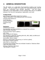
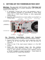
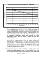
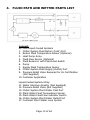
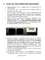
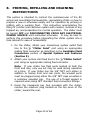
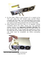
0P1DRCSMNL Revision: X3, 004 Issue Date: 1/06 OPERATING INSTRUCTIONS MANUAL RC Series 19 Inch Rack Mount Recirculating Chiller INTRODUCTION Welcome to the RC Series of 19 inch rack mount recirculating chiller family of products. The RC series chiller is a solid state thermoelectric heating and cooling system designed for maximum precision of thermal control in a space-conserving, convenient package. We would like to take this opportunity to thank you for your purchase. We pledge to provide the highest quality of product with excellent support and service. If we can do anything to make your RC series experience better, please do not hesitate to contact us by phone at 1-877-242-3232 or on the web at www.thermotekusa.com. TABLE OF CONTENTS SECTION PAGE 1. Warnings and Precautions 4 2. General Description 7 3. Setting up the Thermoelectric Unit 8 4. Fluid Path and Wetted Parts List 13 5. Start up and Operating Procedure 15 6. Display Messages, Common Alarms, and Warning Indicators 17 7. Approved Coolants 23 8. Priming, Refilling and Draining Instructions 24 9. Special Options and Features 29 10. General Maintenance 37 11. Specifications 38 12. ThermoTek Communication Protocol and Connection Information 43 13. Additional Equipment/Accessories 54 14. Customer Service Support 61 15. Warranty Information 62 Page 3 of 64 1. WARNINGS AND PRECAUTIONS Immediately upon receiving your new ThermoTek RC series chiller (Recirculating Thermoelectric Heating & Cooling System) inspect your unit. If the unit shows shipping damage, contact the transportation company and file a Freight Damage Claim. Retain all packing material and carton until the unit is operated and found to be in good condition (Please see About the Warranty (Section 16) for more information). For testing purposes at the factory, your chiller was filled with a 10% alcohol, 90% distilled water solution. For transportation requirements the chiller system was drained, yet some residual fluid may remain. In nearly all applications this residual fluid will not hinder system performance, but may be different from the desired coolant to be used in your system. Therefore, it is recommended that you fill and drain the chiller system one time with your desired coolant to fully dilute the residual fluid. Refer to the Priming and Refilling Instructions (Section 8) for instructions on how to fill the chiller and your system with working fluid. Your new chiller system is designed to provide fluid heating and cooling only as specified in this manual. If the system is used in a manner other than as specified, its operation or the safety protection of the system may be impaired. When using your chiller, basic safety precautions should always be followed to reduce the risk of fire, electric shock and personal injury, including the following: 1. Read and follow all instructions and warnings. 2. Unplug this product from any electrical source before cleaning. Do not use liquid cleaners or aerosol cleaners. Use a soft cloth and warm soapy water only. Do not submerge the chiller system. Page 4 of 64 3. Do not place this product on an unstable cart, stand or table. The product may fall, causing serious damage. 4. Slots and openings in the cabinet are provided for ventilation to protect it from overheating. A minimum clearance distance of 6” from the front and rear of this product must be maintained to meet system performance specifications. This product should never be placed near or over a radiator, heat register or a built in installation such as a cabinet unless proper ventilation is provided. 5. Never push objects of any kind into this product through cabinet slots as they may touch dangerous voltage points or short out parts that could result in a risk of fire or electric shock. Never spill liquid of any kind into the product. 6. Do not operate at set points below 5°C without a 80% distilled water and 20% inhibited Glycol solution like Dow Frost Prestone 5/150 or Prestone LOTOX antifreeze. Prestone is trademark of Honeywell International Corporation. 7. Do not operate this product beyond rated capacity. 8. Do not operate this product above or below 10% of the rated input voltage. 9. This product must be plugged into a properly grounded power source. 10. Do not operate this product without fluid in the reservoir. 11. Do not drop the unit or cause impact to the unit. 12. Do not use or maintain this product outdoors as this product was not designed to withstand outdoor weather conditions. 13. Observe all warning labels. Never remove the warning labels. 14. Do not operate this product if it is damaged or leaking fluids. 15. Use only approved fluids. Refer to Approved Coolants (Section 7). Page 5 of 64 16. Do not operate this product with damaged or frayed power cords. 17. Always turn this product OFF and disconnect the power cord from the power source before performing any service, maintenance procedures, or moving the unit. 18. Ensure that this product is installed and prepared for operation according to the instructions in this manual before energizing. 19. All RC series chillers must be supported by internal rails in a rack system. NEVER use mounting slots on the faceplate to support the weight of the unit. See pages 56 - 60 for a suggested rail configuration. Page 6 of 64 2. GENERAL DESCRIPTION The RC chiller is a solid-state thermoelectric heating and cooling system. The unit consists of a pump, fan, electrical circuitry, and at least one solid-state heat transfer assembly. The RC chiller maintains a set temperature of the working fluid that is circulated between the thermal management application and itself. Components: High Output Solid-State Heat/Cool System Twenty Character 2-Line Alphanumeric LCD Module Integral Fluid Reservoir Circuit Breaker Ground Terminal Coolant Pump Fans Features: 19 Inch Form Factor Upgradeable and Downgradable as required by customer User-Friendly Interface Universal Power Input (option) Life Timer Easy to Read LCD Display I/O Interface (optional) Including RS-232, 485, USB, and Ethernet Field Upgradeable Firmware Summation Alarm Output External Temperature Monitoring or Control (option) Fan Speed Control (option) Auto Start on Power-Up Fluid Exposed Metallic Parts are E-Nickel Coated or Stainless Steel Leak Free Disconnects Memory Retention Set Point Top Filling for Coolant Page 7 of 64 3. SETTING UP THE THERMOELECTRIC UNIT Warning: The user must read Precaution #19 in Warnings and Precautions (Section 1), on proper installation and mechanical support of the chiller unit. 1. If applicable, connect the unit to the application using a hose assembly provided by ThermoTek or hoses using Colder PLC or PLCD Insert fittings, or other appropriate mating fittings. 2. Keep the unit horizontal (on a level surface or mounted in a 19 inch rack). Auxiliary Communication Unit Fill/Vent Fitting RS-232 Serial Communication Port Port RJ-45 LAN/USB-B Communication Ports RS-485 Serial Communication Port Unit Serial Label Fluid Outlet Fitting Ground stud Fluid Inlet Fitting AC System Supply Voltage Input See ThermoTek Communication Protocol and Connection Information (Section 12) for additional electrical connector details. 3. Ensure that there is at least a 6-inch clearance and free path for air at the front and rear of the unit prior to operation. 4. Check to see if the input power breaker is in the OFF position. 5. Insert the fluid transport hoses into the machine connections on the Rear Panel of the unit. If Colder PLC, PLCD, or 3/8” hydraulic connections were selected, hearing a “CLICK” indicates a secure connection. Check labels by the connectors for coolant flow direction. Page 8 of 64 6. Install the appropriate end of the power cord into the unit. Plug the male end into the appropriate AC voltage outlet within the specified voltage range. 7. Prime the unit by following the Priming, Refilling and Draining Instructions (Section 8) of this manual; also see Approved Coolants (Section 7). Note: When unit is initially powered up it may be necessary to add more fluid by repeating the Priming and Refilling Instructions (Section 8). 8. If UL 1995 certification was selected (indicated by an ETL logo on the unit’s rating plate), a pressure relief valve must be installed into the piping system and is not included with the RC Series chiller system. This type of protection valve is highly recommended for an RC series chiller with the high pressure pump option (denoted by the “M” in the model number RCX-X-XXMX) even without the UL certification. This valve should be installed at the outlet fluid port of the chiller to ensure maximum safety. 9. It is highly recommended to minimize the potential for dynamic pressure shock damage to the chiller and your system via a water hammer arrestor or good system design practices. Frequent causes of pressure shock damage include but are not limited to the use of solenoid actuated bypass-valves, disconnecting system lines while chiller system is operational or sudden line kinks. Page 9 of 64 RC chiller Customer System Pressure Relief Valve Safe Ejection Location The setting of the relief pressure is dependent on maximum temperature that the system will operate. calculate your relief pressure setting in bars, divide maximum operating temperature by 21.4 and subtract resulting value from 8.3. Refer to the Figure below appropriate pressure settings. [Relief Pressure ] = 8.3 bar - [Max Operating Temp in Celsius ]21.4 Page 10 of 64 the To the the for System Pressure Relief Valve Setting versus Temperature 9 8 7 Pressure, bar 6 5 4 3 2 1 0 0 5 10 15 20 25 30 35 40 45 50 55 60 65 70 75 80 85 Temperature, °C Two recommended sources for this valve are Generant model VRVI Series and Straval model RVI 05 Series. It is also recommended to select the stainless steel valves with threaded outlet port to direct the over pressurized flow to a safe location for ejection from the system. Copper, brass, or untreated aluminum valves will corrode in most applications where the RC chiller is used and are NOT recommended. Note that all pumps used in the RC series chillers are magnetically coupled pumps. In the event the pump is dead-headed, it will decouple thereby relieving the excess system pressure. To re-engage the pump the chiller must be either power-cycled or placed into STANDBY by pressing the RUN/STANDBY button twice. 10. For liquid-cooled RC chillers utilizing a facility plant water system the tubing segment from the plant water to the inlet of the chiller should have both a pressure relief valve and Page 11 of 64 water hammer arrester installed. It is common for plant water systems to have intermittent pressure spike events due to multiple users accessing the plant water loop. Safe Ejection Location Pressure Relief Valve (Optional) Water Hammer Arrestor (Highly Recommended) RC chiller Plant Water System Page 12 of 64 4. FLUID PATH AND WETTED PARTS LIST Legend: Air- and Liquid-Cooled Systems 1. Chiller System Fluid Return (Inlet) Port 2. Return Fluid Temperature Sensor (Optional) 3. Heat Pump Array 4. Fluid Flow Sensor (Optional) 5. Fluid Reservoir with Fluid Level Switch 6. Pump 7. Supply Fluid Temperature Sensor 8. Chiller System Fluid Supply (Outlet) Port 9. Pressure Relief Valve Required for UL Certification (Not Supplied) 10. Customer Application Liquid-Cooled Systems Only: 11. Water Hammer Arrestor (Not Supplied) 12. Pressure Relief Valve (Not Supplied) 13. Chiller System Plant-Water Inlet Port 14. Plant-Water Fluid Temperature Sensor 15. Plant-Water Fluid Flow Indicator Switch 16. Chiller System Plant-Water Outlet Port 17. Customer Plant Water Loop System Page 13 of 64 Wetted Parts List: Fittings Flow Sensor Temperature Sensor Tubing Pump (Low Pressure) Models RCX-X-XXGX Pump (High Pressure) Models RCX-X-XXMX Heat Transfer Assembly Reservoir Sealants Thermoplastic: Nylon Metal: 304 Stainless Steel 316 Stainless Steel Body: Glass Reinforced Polypropylene Rotor Pin: Ceramic Rotor: PPS Composite, Black Lens: Polysulfone O-Ring: Buna-N Body: 306 Stainless Steel Nitrile Based Synthetic Rubber1 Body: Noryl (PPO)2 Blade: Liquid Crystal Polymer3 Shaft: 99.5% Pure Alumina Ceramic Bearing: Glass Filled Teflon O-Ring: EPT (Y-54) Body: 316 Stainless Steel Gear: Riton Static Seals: Buna-N Body: Electroless Nickel Body: Float Level: O-Ring: Plug: Teflon Silicone 1 Electroless Nickel Polypropylene Buna-N 316 Stainless Steel – Nitrile Synthetic Rubber with Proprietary Additive (Parker-Hannifin) – 30% Glass Fiber Filled Polyphenelyne Oxide (GE Materials) 3 – Vectra Glass and Carbon Filled Thermoplastic Resin (Celanese Chemical) 2 Page 14 of 64 5. START UP AND OPERATING PROCEDURE 1. Verify that the unit is plugged into the appropriate AC voltage outlet. 2. Turn ON the unit. The input power breaker switch is located on the rear panel. 3. When the unit is first powered up, a green back light will be on the display screen located on the front of the unit. Messages will then appear on the display screen indicating system model and firmware revisions. 4. After turning the unit ON you may get a message on the display screen that reads “!!ALARMS ACTIVE!! LOW COOLANT LEVEL!” If so, repeat the Priming Procedure for the RC Thermoelectric Unit. Once completed, press the RUN/STANDBY key to clear the alarm. 6. During the power up sequence, there will be a moment where the keypad is disabled and you will hear the pump being powered up and brought to speed. If the FAN SPEED CONTROL option was selected, then there will be a short delay before the fans are initiated at full speed. Otherwise, the fans and pump are initiated simultaneously. This sequence will be repeated each time the unit is powered up or taken from standby to operation. 7. The unit will automatically control to 20°C or the last user selected set temperature. 8. To stop the coolant flow to your application, press the Run/Standby button located on the left side of the display Page 15 of 64 panel. A display message will read “Standby Mode” when the unit has stopped running. If the FAN SPEED CONTROL option was selected, the fans will turn off after 30 seconds. Otherwise, the fans will continue to run. To restart the unit, press the Run/Standby button. 9. Set the chiller to the desired temperature. To change the set temperature, press the Menu button (lower right) until the display reads Set Temperature. To lower the water temperature, press the Down button on the front panel. To raise the fluid temperature, press the Up button on the front panel. The new set temperature value is automatically saved in memory until the next time it is changed. Note: If you hold the button down, the set point will scroll in tenths of degrees and then change to full °C increments. 10. To determine the current water temperature in your application, press the Menu button until the display reads either Coolant Temperature or Supply Temperature. If the FLOW option was selected, you also have access to the chiller’s Return Temperature, Ambient Temperature, and coolant Flow Rate. If the EXTERNAL TEMPERATURE PROBE option was selected and connected, you also have access to the External Probe Temperature. 11. In Standby Mode press the menu key to display the unit operational hours (Life timer). Page 16 of 64 6. DISPLAY MESSAGES, COMMON ALARMS, AND WARNING INDICATORS Display Messages The RC series chiller has two operational modes: RUN and STANDBY. Each operational mode has specific display messages. RUN mode In RUN mode, all of the chiller’s applicable sensors and the desired control temperature are available through MENU selection on the keypad. SUPPLY TEMPERATURE: Indicates the current outlet temperature of the coolant to your application. SET TEMPERATURE: Shows the current desired coolant temperature. This can be adjusted by pressing the UP and DOWN keypad buttons to the desired temperature setting. Pressing and holding the UP or DOWN keypad buttons will scroll the temperature setting. RETURN TEMPERATURE: FLOW option only. Shows the current inlet temperature of the coolant returning to the chiller unit. Alarm/Warning Display: If any non-critical alarm or warning is currently active on the chiller, every menu screen will flash “ALARM ACTIVE” or “WARNING ACTIVE” along the top line of the display. Press the MENU button to scroll through the menus until you reach the Alarm/Warning Display screen where the name of the alarm or warning is shown. A discussion and list of non-critical alarms and warnings can be found in a lower portion of this section. EXT RTD TEMPERATURE: EXTERNAL RTD TEMPERATURE PROBE option only. Shows the current remote RTD probe temperature if connected and enabled. Page 17 of 64 EXT THERM TEMPERATURE: EXTERNAL THERMISTOR TEMPERATURE PROBE option only. Shows the current remote thermistor probe temperature if connected and enabled. PLANT TEMPERATURE: LIQUID COOLED CHILLER option only. Shows the current plant loop inlet temperature. AMBIENT TEMPERATURE: AIR COOLED CHILLER option only. Shows the current ambient air inlet temperature. PROCESS FLOW: FLOW option only. Shows the current coolant flow temperature rate in liters/minute (LPM) ± 0.1 lit/min accuracy. TEMP CONTROL: EXTERNAL TEMPERATURE PROBE option only. When the user has connected and enabled their external RTD or Thermistor temperature probe, this menu allows the user to select which sensor they want the chiller to control the coolant temperature to. Options here may contain the following depending on options selected: INT SUPPLY SENSOR, EXT 100 OHM RTD, INT RETURN SENSOR, and EXT 10K THERMISTOR. See the Auxiliary Input/Output portion of ThermoTek Communication Protocol and Connection Information (Section 12). STANDBY mode Standby Mode indicates that the chiller pump is off and the unit is ready for use. Press the RUN/STANDBY button to begin the pump and fans (if applicable) and start the heating/cooling control of the application. Press the MENU button to scroll through the menu options. LIFE TIMER: Displays total number of hours the system has been run. Page 18 of 64 CONTROL MODE: The RC series thermal control PID algorithm has two modes of operation, DEFAULT and LOW FLOW. The LOW FLOW control mode is available only for applications where the coolant flow rate is lower than 1.0 LPM (0.25 Gal/min). Otherwise, the DEFAULT control mode is recommended for thermal stability and response. The control mode is automatically saved in memory until changed by the user. LEVEL SW DETECTION: For customers who utilize an external coolant reservoir, users can temporarily disable the chiller’s internal fluid level switch by changing this selection from ON to OFF by pressing the UP arrow button. This selection is temporary and will reset back to ON whenever the chiller is power cycled. Alarm/Warning Display: If any non-critical alarm or warning is currently active on the chiller, every menu screen will flash “ALARM ACTIVE” or “WARNING ACTIVE” along the top line of the display. Press the MENU button to scroll through the menus until you reach the Alarm/Warning Display screen where the name of the alarm or warning is shown. A discussion and list of non-critical alarms and warnings can be found in a lower portion of this section. COMM LINK: RS-485, RJ-45 ETHERNET LAN, and USB options only. For users who wish to utilize additional communications capabilities, this menu is used to select the method of communication by pressing the UP arrow button to scroll through the options: RS232, USB, ETHERNET, and RS485. The selection is automatically saved in memory until changed by the user. RS-485 DEVICE ID: RS-485 option only. For RS-485 Multi-drop network users, use this menu to set the device identification number between 2 and 32 by pressing the UP and DOWN arrow keys to scroll through. The ID is automatically saved in memory until changed by the user. Page 19 of 64 FAN SPEED CONTROL: FAN SPEED CONTROL option only. This menu selection allows the user to choose from two different reduced fan speed levels: LOW SPEED and HIGH SPEED. See the Fan Speed portion of Special Options and Features (Section 9) for details on how the automatic fan speed control operates. Alarm and Warnings The RC series chiller features alarms of three types: Critical Alarms, Non-Critical Alarms and Warnings. Critical Alarms, Non-Critical Alarms, and Warnings are a measure of error severity. Latched alarms and Non-Latched alarms dictate the amount of user intervention needed to properly clear an alarm. When an alarm is initiated, an indicator is displayed as to what type of alarm has been activated and what the alarm name is. Latched versus Non-Latched Alarms Latched Alarms, regardless of severity, are alarms that once cleared (sensor data has returned to normal operating range) remain in a locked state and require user or communication intervention for the chiller system to return to a normal operating RUN mode. If an alarm is of the non-latched type, once the alarm status has cleared, the chiller will return to normal operation automatically. Critical Alarms Critical Alarms are alarms that are essential to proper chiller system operation and function. Only critical alarms can be of the Latched type. The chiller system cannot operate while a critical alarm is active. Below is a list of critical alarms that may occur during normal operation and how system operation is automatically changed as a result of an Active Critical Alarm event. If a critical alarm cannot be cleared by user intervention, contact ThermoTek Customer Service for assistance. Page 20 of 64 Critical Alarms Display Message CONFIG ERROR. Press UP & DOWN to default FLOW SENSOR ERROR LCD BUSY LOW COOLANT LEVEL NO PROCESS FLOW PLANT COOLANT FLOW RS232_TI_ERR OR SUPPLY TEM > DEFAULT SUPPLY TEM < DEFAULT SUPPLY SENSOR FAIL-O SUPPLY SENSOR FAIL-S SUPPLY SENSOR FAIL-L SUPPLY SENSOR FAIL-C Heat Transfer Function OFF Coolant Pump Function OFF OFF OFF YES LCD Busy Error Low Coolant Level in the Reservoir No Coolant Flow Detected OFF OFF OFF OFF YES YES OFF OFF YES Low Plant Coolant Flow OFF NO CHANGE YES RS232 Transmit Error OFF OFF YES Supply Temp is greater than max allowed Supply Temp is lower than min allowed Supply Temperature Sensor Open Alarm Supply Temperature Sensor Short Alarm Supply Temperature Sensor Locked Alarm Supply Temperature Sensor Alarm Cleared OFF NO CHANGE NO CHANGE NO CHANGE NO CHANGE NO CHANGE NO CHANGE NO Description Configuration Error. Pressing UP & DOWN (together) will set Default configuration. Contact ThermoTek. Coolant Flow Sensor Error OFF OFF OFF OFF OFF Latched? YES NO YES YES YES YES Non-Critical Alarms and Warnings Non-Critical Alarms and Warnings are alarm indicators that may affect the proper display and communication of sensor information or are active because some aspect of chiller operation has exceeded desired parameters. These events are not critical to the operation and coolant control of the chiller system and will not alter thermal control or pump activity. However, all alarm and warning events should always be addressed and corrected. None of the Non-Critical Alarms or Warnings are of the Latched type. The alarms shown in the following two tables may not be available on all RC series chiller systems due to options selected by the customer at the time of purchase. Page 21 of 64 Non-Critical Alarms Display Message AMBIENT SENSR FAIL-O AMBIENT SENSR FAIL-S AMBIENT SENSR FAIL-C AUX CONECTOR MISSING EXT RTD SENSR FAIL-O EXT RTD SENSR FAIL-S EXT RTD SENSR FAIL-C EXT THRM SENR FAIL-O EXT THRM SENR FAIL-S EXT THRM SENR FAIL-C FRONT LEFT FAN-HiRPM FRONT LEFT FAN - O FRONT RIGHT FAN-HiRP FRONT RIGHT FAN - O HIGH AMB TEMP ALARM HIGH PLANT TEMP ALRM HIGH TEMP ALARM LOW AMB TEMP ALARM LOW PLANT TEMP ALARM LOW TEMP ALARM PLANT FLOW INPUT - O PLANT FLOW - HiFreq PLANT SENS0R FAIL-O PLANT SENS0R FAIL-S PLANT SENS0R FAIL-C PROCESS FLOW ALARM PROCESS FLOW INPUT - O PROCESS FLOW - HiFreq RETURN SENSOR FAIL-O RETURN SENSOR FAIL-S RETURN SENSOR FAIL-C REAR LEFT FAN-HiRPM REAR LEFT FAN - O REAR RIGHT FAN-HiRPM REAR RIGHT FAN - O Description Ambient Temperature Sensor - Open Alarm Ambient Temperature Sensor Short Alarm Ambient Temperature Sensor Alarm Cleared Presence of Auxiliary connector not Detected External RTD Sensor Open Alarm External RTD Sensor Short Alarm External RTD Sensor Alarm Cleared External Thermistor Sensor Open Alarm External Thermistor Sensor Short Alarm External Thermistor Sensor Alarm Cleared Front Left Fan Signal – Noise Front Left Fan - No Signal / Open Front Right Fan Signal – Noise Front Right Fan - No Signal / Open Ambient Temp is above User spec Max Value Plant Temp is above User spec Max Value Supply Temp is above User spec Max Value Ambient Temp is below User spec Min Value Plant Temp is below User spec Min Value Supply Temp is below User spec Min Value Plant Flow - No Signal / Open Plant Flow Signal - Noise Plant Coolant Temp. Sensor Open Alarm Plant Coolant Temp. Sensor Short Alarm Plant Coolant Temp. Sensor Alarm Cleared Coolant Flow is below User spec Min Value Process Flow - No Signal / Open Process Flow Signal – Noise Return Temperature Sensor Open Alarm Return Temperature Sensor Short Alarm Return Temperature Sensor Alarm Cleared Rear Left Fan Signal – Noise Rear Left Fan - No Signal / Open Rear Right Fan Signal – Noise Rear Right - No Signal / Open Warnings Display Message HIGH AMB TEMP WARNIN HIGH PLANT TEMP WARN HIGH TEMP WARNING LOW AMB TEMP WARNING LOW PLANT TEMP WARN LOW TEMP WARNING PROCESS FLOW WARNING SUPPLY IS CNTRL TEMP Description Ambient Temp is above User spec Max Value Plant Temp is above User spec Max Value Supply Temp is above User spec Max Value Ambient Temp is below User spec Min Value Plant Temp is below User spec Min Value Supply Temp is below User spec Min Value Coolant Flow is below User spec Min Value Supply Temp Sensor is the current Control Temp Sensor (due to error on User spec Control Sensor) Page 22 of 64 7. APPROVED COOLANTS 1. Distilled water: For operation from 5°C to 45°C only. Replace monthly to prevent biological growth. 2. Deionized water: To 7 Mohms for operation from 5ºC to 45ºC only. Replace every 90 days or with cartridge replacement to prevent biological growth. 3. 95% distilled water and 5% alcohol mixture prevents bacterial growth. Replace every 90 days. 4. 80% distilled water and 20% corrosion inhibited Glycol. Use for set temperature below 5°C only. Example: Dow Frost Prestone® 5/150 or Prestone® LOTOX Antifreeze approved for aluminum exposure. Replace every 90 days. Prestone® is a registered trademark of the Honeywell International Corporation. Note: These fluids are the only approved coolants to be used and covered under warranty. Page 23 of 64 8. PRIMING, REFILLING AND DRAINING INSTRUCTIONS This section is intended to instruct the customer/user of the RC series rack mountable thermoelectric, recirculating chiller on how to prepare a new or otherwise empty unit for operation by priming or refilling with a working fluid. This instruction accomplishes the filling of a chiller and customer system with coolant, removal of any trapped air, and preparation for normal operation. The chiller must be turned OFF and DISCONNECTED FROM ANY ELECTRICAL POWER SOURCE until instructed otherwise. It may be best to perform this procedure before integrating the chiller system into a rack cabinet for ease of accessibility. 1. On the chiller, attach your closed-loop system outlet fluid line to the “Chiller Inlet” port using an appropriate mating fluid connector as described in the Available Fluid Connectors portion of Special Options and Features (Section 9). 2. Attach your system inlet fluid line to the “Chiller Outlet” port using an appropriate mating fluid connector. Note: If your chiller has fluid ports located at both the front and rear, only one set may be used during operation at a time. If your chiller has the 3/8” NPT port option in addition to having front and rear ports, the unused ports must be plugged using either the 3/8” NPT caps provided or a customer supplied cap. The use of a thread sealant is required when using NPT standard fluid connection fittings. 3. Using the hexagonal key tool provided with the chiller, remove the reservoir plug located on the top cover of the chiller, toward the rear. Page 24 of 64 4. On the chiller, attach a tube at least 2 ft. in length to the “Fill” port using the 3/8” barbed quick connect fitting1 provided with the chiller. It is recommended to use a clear or translucent tube. The “Fill” port is the uppermost female 1/4” quick connect fitting located at the rear of the chiller. 5. While holding the tube from step 4 in an elevated, vertical orientation above the chiller, slowly pour the premixed coolant solution (see Approved Coolants (Section 7)) into the reservoir until coolant reaches the lower portion of the reservoir neck. If any coolant was spilled into or down the back side of the chiller during this step, the chiller and rear panel must be completely dry before proceeding further. 1 Part is a Colder Products® P/N: PLCD2200412 Page 25 of 64 6. While keeping the fluid tube elevated, attach the electrical AC power cord to the chiller and switch the breaker to the ON position. After a short 3-second boot up sequence, the chiller will automatically enter RUN mode and the pump will engage. 7. If the system was dry or the coolant level was low enough, the pump may pull all of the coolant out of the reservoir and disengage when the fluid level switch activates the system alarm. If this occurs, the chiller defaults into STANBY mode with a LOW COOLANT LEVEL alarm and more coolant must be added. If so, repeat step 5 once. WARNING: NEVER ADD COOLANT WHILE THE PUMP IS RUNNING. COOLANT LINES EXPAND WHEN PRESSURIZED AND MAY HOLD MORE COOLANT THAN PERCEIVED. STOPPING THE PUMP OR TURNING THE SYSTEM OFF AFTER AN OVERFILL MAY CAUSE COOLANT TO EJECT FROM THE RESERVOIR AND CAN CAUSE SERIOUS INJURY OR ELECTRICAL DAMAGE. 8. If after repeating step 5 one time your reservoir still empties and the pump automatically disengages, continue to repeat step 5 until the pump does not disengage on its own. When this occurs, turn off the chiller by switching the breaker to the OFF position or place the system into STANDBY mode by pressing the keypad button “RUN/STANDBY” one time. 9. With the coolant pump disengaged and the “FILL” fluid tube elevated above the chiller, you can top-off the coolant in the reservoir. 10. Turn the chiller ON once again and allow it to run without the reservoir plug for at least 5 minutes in order to purge all remaining air from the coolant fluid lines. It is advised to monitor the coolant temperature periodically during this step and adjust accordingly. Note: Failure to purge all air bubbles from the coolant lines will adversely affect coolant temperature stability and the thermal performance of the chiller system. Page 26 of 64 11. Repeat step 9 and replace the plug using the hexagonal key tool. 12. Remove the “FILL” fluid tube from the rear of the chiller system. The chiller, coolant lines and your application are now primed and ready for use. Draining Your RC Series Chiller/Preparing for Long-Term Storage Whether you are planning on storing or not running your RC series chiller system for a period greater than 3-months, it is important to drain the coolant from your system to reduce the risk of damage by corrosion and bacterial growth. Even coolant mixtures that may contain growth and corrosion inhibitors can potentially separate and/or dilute when not agitated or mixed for prolonged periods. Using Compressed Air: 1. Place the RC series chiller system on a flat, level surface. 2. Leaving the reservoir plug in place and sealed, attach one end of a fluid line into the “Chiller Outlet” port and the open end into a waste coolant container (a 1-gallon container is recommended). 3. Set the compressor output line to 10 pounds-per-squareinch [PSI] and attach the compressed air into the “Chiller Inlet” port to begin the fluid ejection process. Note: Protect yourself and any surrounding equipment from any fluid spray that may occur during this process. 4. Tilt the rear end of the unit up a few inches and then rest the chiller back onto the flat, level surface. Allow the compressed air to run through the chiller for approximately 20 seconds for sufficient drying. 5. Disconnect all fluid and air lines from the unit. Properly dispose of any waste coolant that contains fungicide, glycol, or other growth/corrosion inhibitors or chemicals following your local laws and regulations. Potentially toxic fluids should never be disposed of improperly. Page 27 of 64 6. Your RC series chiller system is now drained and ready for storage. Without Compressed Air: 1. Place the RC series chiller system on a flat, level surface. 2. Prepare two tubes, each having one mating connector and one open tube end. 3. Attach the mating connector ends of the tubes to the “Chiller Outlet” and “Chiller Inlet” ports and the open ends into a waste coolant container (a 1-gallon container is recommended). 4. Turn the chiller on and allow the pump to eject the coolant into the container. Note: the pump should stop on its own when the LOW COOLANT LEVEL alarm is triggered. If the alarm does not trigger automatically, power OFF the chiller. 5. With the waste coolant container located below the chiller, remove the reservoir plug using the hexagonal key tool provided. Any remaining coolant should begin to slowly drain out on its own. 6. Allow the chiller to drain for approximately 5 minutes. 7. After this time, tilt the front end of the unit up by the handles a few inches. Rest the chiller back onto the flat, level surface and tilt the rear end of the unit up a few inches. This may dislodge any coolant trapped by airbubbles in the tubing lines. Rest the unit back onto the flat, level surface and allow it to sit for an additional 5 minutes. 8. Replace the reservoir plug and disconnect all fluid lines from the unit. Properly dispose of any waste coolant that contains fungicide, glycol, or other growth/corrosion inhibitors or chemicals following your local laws and regulations. Potentially toxic fluids should never be disposed of improperly. 9. Your RC series chiller system is now ready for storage. Page 28 of 64 9. SPECIAL OPTIONS AND FEATURES The RC series chiller system was designed to be modular and configurable in order to maintain a highly diverse thermal platform. The part number scheme for the RC series chiller consists of twenty-three characters; two are fixed, five are controlled by the factory, and the remaining fifteen are variable to meet the needs of the application. Below is a detailed explanation of the part number character positions and their implication to the performance and platform characteristics of the RC series chiller system. Chiller Type, character 3 A: Air cooled – Our standard configuration, this offers the customer a highly portable operating capability and industry leading cooling capacity in the 3U cooling package. This chiller features a modular liquid-to-air heat exchanger platform, offering our customers the ease and cost-effectiveness of configuring a chiller with a thermal capacity matched to their application needs. L: Liquid cooled – Originally designed for use in laboratories and fabrication facilities that feature a plant-water coolant loop, this chiller system features the same modular heat exchanger platform in a liquid-to-liquid version. This chiller type also offers our customers increased cooling capacity in the same compact package. Chiller Unit Depth, character 4 1: 15” – The shorter 15” chassis offers cooling capacities up to 450 Watts in the air-cooled and 650 Watts in the liquid-cooled versions. 2: 22” – The longer 22” chassis offers cooling capacities up to 750 Watts in the air-cooled and 1150 Watts in the liquid-cooled versions. This longer chassis also accommodates the use of the optional 1 gal/min, 6-bar gear pump. Page 29 of 64 Fluid Connection Location, character 5 The RC series chiller offers two coolant port locations, at the front and/or rear of the chiller. R: Rear Ports – Our standard option; fluid connections are located at the rear of the chiller. This option is commonly used for all medical and industrial applications. F: Front Ports – Commonly selected for laboratory applications, this offers our customers the convenience and ease of a fluid connection at the front of the system. This option is beneficial when the chiller is mounted in a rack fixture and the chiller is interchanged with multiple applications. B: Front and Rear Ports – This option is rare but useful to those in laboratories where chiller versatility is critical, giving the customer the choice of using either the front or rear ports. Available Fluid Connections, character 6 There are four different fluid connection options available on the RC series chiller system to make integration into your application as easy as possible. 0: ¼” Flow Thermoplastic Female Quick Disconnect – Example is the Colder PLC12 Series. Our standard option; ideal for nearly all medical and laboratory applications. These couplings feature chemically resistant thermoplastic material. 1: ¼” Flow Chrome-plated Brass Female Quick Connect – Example is the Colder LC Series. This option is an enhanced and more robust version of our standard thermoplastic fitting option. The chrome plated body and EPDM seals make for higher resilience in thermal, physical stress, and chemical corrosion aspects. 2: 3/8” NPT Ports – Made from 316 grade stainless steel, this option is ideal for industrial application where the chiller is located in a fixed position for dedicated equipment. This option offers the lowest resistance to coolant flow and greatest corrosion resistance using industry proven 316 grade stainless steel. This option is ideal for those who choose to use de-ionized water. Page 30 of 64 3: 3/8” Hydraulic Quick Coupling – Example is the Parker 60 series. Also constructed of 316 grade stainless steel, these couplings offer all of the low flow resistance and corrosion resilience of the NPT option with the added benefit of a quick coupling design. This option is ideal for heavy-use industrial application where strength and portability are vital. Input Voltage, character 7 U: Universal Voltage Input – Being capable of using any AC voltage input between 100-240 volts at 50 or 60 Hz makes the RC series chiller system as versatile as can be, able to run nearly anywhere in the world where AC power is available. Safety Listings, character 8 Consumer safety is of the utmost importance to ThermoTek and its customers. For this reason, the RC series chiller is available to meet UL 1995 for electrical emissions safety. RC series chillers meeting this requirement can be identified by the ETL insignia on the rating plate. Thermoelectric Chip Series, character 9 In an effort to get maximum performance and life out of your RC series chiller, ThermoTek offers three versions of thermoelectric chips to meet the needs of every possible application. D: Standard Chips – This option offers the best performance for the cost. These chips are ideal for applications where the desired coolant temperature is typically steady during chiller use. X: High-Cycle Chips – This option exhibits a slight decrease in thermal performance when compared to our standard chip design but makes up for it in its extremely long life. The most common failure mode for thermoelectric chips is attributed to the extreme stresses caused by thermal cycling. Not a problem for these chips as they were designed for just that, thermal cycling applications. H: High-Performance Chips – This option offers increased thermal performance when compared to our standard chip design, especially in large dT applications. Large dT applications are when the desired coolant temperature is greater than 15ºC below the Page 31 of 64 ambient cooling medium temperature. Examples of this type of application are when the desired coolant temperature is near 0ºC or when the chiller is operating in a hot ambient environment. Heat Transfer Assembly and Power Supply Quantities, characters 10 and 11 In an effort to provide a cost-effective chiller with a thermal capacity matched with the customer’s individual needs, the modular heat exchanger platform was created. This platform allows ThermoTek Application Engineers to work with the customer and configure a RC chiller system with a single (1), double (2), or triple (3) heat exchanger construct. Pump Type, character 13 There are currently three options available to customers using the RC series chiller for their thermal management application. G: Low Pressure Centrifugal Pump – Our standard option; a 10.5 psi, 1-gal/min centrifugal pump. This pump features a 12-volt brushless DC motor for long life and magnetic-coupled drive to virtually eliminate coolant heating from the motor. This pump is ideal for medical and laboratory applications where equipment is typically sensitive to higher operating pressures. M: High Pressure Gear Pump – The high pressure pump option features a 90 psi, 1-gal/min gear style positive displacement pump. Using a high-torque, long-life AC motor and pump head, this option is well suited for higher coolant flow applications in the industrial market. E: External Pump – For those customers that already have a pump in their application or have a pump they just love, the RC series chillers can come with no pump at all. Minimum flow rate and maximum pressure limitations must be discussed with ThermoTek’s Application Engineers. The “Flow Measurement” option must be selected with this pump option. Page 32 of 64 Fan Speed, character 14 Audible noise produced by the chiller system anywhere near people is often a concern. This is why ThermoTek offers our customers two different fan speeds and automatic fan speed control capability. All RC chiller systems come equipped with a removable left-side faceplate containing air filters. E: Low Speed – Our standard option; offers superior thermal performance at a low audible noise level of 49 dBA. S: High Speed – For increased thermal performance and faster thermal response, the high speed fan option is ideal for higher heat load, thermal shock applications and industrial environments. T: Automatic Fan Speed Control – For customers who want the benefit of maximum thermal performance only when the demand is present, customers can choose the benefits of automatic fan speed control. Utilizing the high speed fans and a custom controller board, the fans will start up at full speed and automatically decrease to a user selectable “LOW” and “HIGH” reduced speed levels when three criteria are met. 1. The coolant supply temperature must be within 0.5ºC of the setpoint. 2. The power drive level to the heat exchanger must be below a preset threshold. 3. The chiller must maintain criteria 1 and 2 for a period of 3 minutes to ensure stability. Once all these are met, the fan speed will reduce to the user selectable level and additional power is applied to the heat exchanger to compensate. The fans will return to full speed if either criteria 1 or 2 are violated. When the chiller is placed into Stand-By mode the pump will stop and the cooling fans will return to full speed for 30 seconds to dissipate any remaining energy in the heat exchanger(s). After the 30 second period is complete, the fans in the cooling section will stop completely to render the RC series chiller system nearly silent. Page 33 of 64 Fan Quantity, character 15 Only available for the “Low Speed” fans, this option increases the quantity of fans in the cooling section from four to six. This increases the thermal capacity and response of the chiller system without significantly increasing audible noise. Flow Measurement, character 18 0: No Coolant Flow Measurement 1: Coolant Flow Measurement – This option not only adds a calibrated FLOW METER into the chiller coolant path, but adds two more temperature sensors as well; a RETURN coolant temperature probe and an AMBIENT probe (either cooling air or plant water). Since every RC chiller system comes equipped with a SUPPLY coolant temperature probe, this option can turn your system into as much an instrument as it is a water chiller. With the standard RS232 communication interface that comes already on the RC series chiller, customers can poll and log total system performance data for every probe in the system. This allows customers to monitor chiller system performance and coolant stability over time or at any instant. This option has strong benefits for customers in all industries and nearly all applications. External Temperature Probe, character 19 In addition to the RS-232 communication interface connector included free on every RC series chiller is an Auxiliary interface connector. The Auxiliary interface (connection and capability details discussed in the ThermoTek Communication Protocol and Connection Information (Section 12)) includes a summation alarm output and external probe connectivity. 0: No external probe capability R: 100-ohm RTD capability (2 or 4-wire) – With inputs located on the Auxiliary connector, the RTD input allows customers to interface their own temperature probe to the RC series chiller for the purpose of temperature monitoring or coolant temperature control. Available through the chiller display menu, the user can activate or de-activate the external probe and (in most applications) even Page 34 of 64 select to control from the external probe. When instrument capabilities like probing and data logging at a critical application point or when coolant temperature precision at the application are vital, this option is a must-have. See the Auxiliary Input/Output portion of the ThermoTek Communication Protocol and Connection Information (Section 12) for additional details and assistance with temperature probe selection for your application needs. T: 10-kohm Thermistor capability – This option is identical to the RTD probe capability but allows the customer to use a Thermistor instead of an RTD. See the Auxiliary Input/Output portion of the ThermoTek Communication Protocol and Connection Information (Section 12) for additional details and assistance with temperature probe selection for your application needs. S: Both 100-ohm RTD and 10-kohm Thermistor capability – This option allows users to utilize both the RTD and Thermistor channels on the Auxiliary connector to give more sensor diversity in operating environments and additional process data. Communication Options, character 20 Giving our customers as much information about the RC series chiller system during operation is an important aspect to continued performance and usability. For this reason, ThermoTek has always offered an RS-232 Serial Communication interface with every standard product, including this RC series chiller system. However, the RS-232 interface is not always optimum for customers with multiple systems or those in remote locations. This is why the RC series chillers now feature a RS-485 multi-drop serial interface, an Ethernet LAN interface, and an USB interface. RS-232 Serial Communication Interface – RS-232 communication is a widely used interface, available on nearly all PC’s (COM ports). This option comes free with every chiller system. Communication protocol and connector pin-out details can be found in Section 12. Some of the benefits of users employing the communication interface are process automation, process or experiment data logging, user configurable alarms and warnings, and remote operation capability. Data logging is made simple with the ability to Page 35 of 64 poll data from every internal sensor the RC series chiller has. With the ability to change the operating mode between RUN and STANDBY and the ability to change the coolant set point temperature via the communication interface, users can automate industrial processes and laboratory experiments. RS-485 Multi-drop Serial Communication Interface – Best suited for industrial applications where a daisy-chain serial network is already in use, the RC series offers seamless integration. Users can easily set the network ID on the chiller and implement the command protocol into their existing system for continuous monitoring and control. RJ-45 Ethernet LAN and USB Communication Interfaces – When complete integration and monitoring of a RC series chiller in a remote location is critical for your application or common for your industry, ThermoTek offers a packaged option that gives users the easiest form of “plug and go” interfacing available. Both RJ-45 Ethernet network and USB ports are available giving users the ability to control and monitor the health of their system and RC series chiller from anywhere in the world with an Internet connection. Rail Kit Included, character 21 For many instrument rack structures, finding just the right rail supports can be a hassle. This is why ThermoTek has designed an adjustable rail kit for the seamless integration of your RC series chiller system into your mounting structure. Adjustable from 15” to 29” long, the rail kit fits nearly all standard 4-post instrument rack structures. Contact ThermoTek Application Engineers for compatibility details. Page 36 of 64 10. GENERAL MAINTENANCE 1. Change the fluid in the unit at intervals and using coolants as specified in Approved Coolants (Section 7). Drain and prime/refill the unit using the Priming, Refilling, and Draining Instructions (Section 8). 2. Clean the exterior of the unit with a soft cloth and warm soapy water. 3. Do not use abrasive or solvent-based cleaners. 4. Do not immerse the unit in water or any liquid. 5. Keep water away from vents, the power input power breaker switch and the power cord connection. 6. Clean the filter once a month or on an as needed basis. a. Turn the unit OFF. b. Use a vacuum cleaner and clean the filters from the front of the unit (then proceed to step e. below). If vacuuming is not sufficient, remove the Left Front Filter Panel (remove the four screws) from the unit and perform these additional steps: c. Wash the filter with warm soapy water. Rinse and remove all excess water. Ensure the filter is dry before re-installing. d. Replace the Left Front Filter Panel. e. Return the unit to operation by following the start-up procedure. Note: The fan air filters are the ONLY user serviceable parts on the RC series chiller system. To avoid possible electric shock, do not remove the top cover. The warranty is voided if the tamper seals are removed or broken. Keep objects that obstruct the airflow at least 6” away from both the front inlet and rear exhaust fans. Page 37 of 64 11. SPECIFICATIONS ThermoTek RC Series Part Number Dimensions1 NXXXXXXXXXXXXXXXX-XXXXXX (See part numbering explanations in Section 9 for details) 5.25 inch T x 15 inch (N3X1…) x 19 inch W (133mm T x 381mm D x 483mm W) Or 5.25 inch T x 22 inch (N3X2…) D x 19 inch W (133mm T x 559mm D x 483mm W) Ambient Operating Range (Air and Plant Water) Coolant Operating Temperature Range 10°C to 40°C (50°F to104°F) Indoor Use Only Cooling Capacity1 Up to 750 watts with set point at ambient air temperature (Up to 1150 watts with set point at Plant Water Supply temperature on Liquid Cooled model) Pump1 Up to 1.0 US gpm (3.86liter/min) open flow water Minimum Flow Minimum 0.2 US gpm (0.76 liter/min) Weight1 22 to 55 lbs (10 to 25kg) Shipping Weight1 5°C to 45°C with Coolant Option 1-3 -5°C to 45°C with Coolant Option 4 (See Approved Coolants (Section 7)) Up to 67 lbs (30.4kg) 1 Power Consumption 625 watts to 1200 watts Input Voltage (Nominal) 100-240 VAC 50/60Hz 1 – Dependent on what options are selected. Page 38 of 64 Specifications – continued Pump Configuration1 Models RCX-X-XXGX 12V brushless motor Models RCX-X-XXMX AC motor w/ automatic 115/230 VAC switching capability Fan Configuration1 12VDC Brushless Motor Port Coupling Bodies1 Colder PLC ¼” Coupling (standard) 3/8” Hydraulic Coupling 3/8” NPT Male Colder Chrome-Plated Brass LC ¼” Coupling Stability ±0.1°C @ minimum 0.6 US gpm flow, constant load at a constant ambient (not to exceed system capacity) Max Current1 7.5 Amps to 12 Amps Audible Noise1 45-60 dBA Refrigerant None Heating/Cooling Function Yes Communication1 RS-232 Serial RS-485 Multi-Drop Serial RJ-45 Ethernet LAN USB 1 – Dependent on what options are selected. Page 39 of 64 Base Rack Mount Chiller Performance Envelope 1200 W N3L2R0U0D32XGS0XX-0000XX Liquid 22" Only N3A2R0U0D32XGS4XX-0000XX Air Max 22" 1000 W N3A1R0U0D21XGS4XX-0000XX Air Max 15" N3A2R0U0D11XGE4XX-0000XX Air Baseline 800 W Thermal Capacity 600 W 400 W 200 W -35 ºC -30 ºC -25 ºC -20 ºC -15 ºC -10 ºC 0W 0 ºC -5 ºC Set Minus Ambient Temperature Thermal performance show n w ith air filter and 0.7 bar centrifugal pump. 3.8 lpm gear pump has a 25 watt decreasing shift in the thermal curves. Available Rack Mount System Pump Curves for Distilled Water at 25 ºC 7.0 bar 6.5 bar 3.8 LPM Gear Pump 6.0 bar 0.7 bar Centrifugal Pump 5.5 bar 5.0 bar System Pressure 4.5 bar 4.0 bar Useful Conversions 1 gpm = 3.8 lpm 1 bar = 14.5 psi System Pump MTBF with Distilled Water 4.8 bar => 6,000 hrs 3.1 bar => 12,000 hrs 1.4 bar => 18,000 hrs Note: Longer Life with 15% Glycol 3.5 bar 3.0 bar 2.5 bar 2.0 bar 1.5 bar MTBF => 25,000 hrs 1.0 bar 0.5 bar 0.0 bar 0.5 LPM 1.0 LPM 1.5 LPM 2.0 LPM 2.5 LPM 3.0 LPM 3.5 LPM 4.0 LPM Process Flow The performance of the chiller is based on Recirculating water with a 0.6-gpm flow. Individual applications will affect chiller performance. ThermoTek must approve all applications to maintain warranty and performance specifications are subject to change without notice. Page 40 of 64 Page 41 of 64 Page 42 of 64 12. THERMOTEK COMMUNICATION PROTOCOL AND CONNECTION INFORMATION The unified Communication Command Protocol for the RC series chiller systems can be found on ThermoTek’s website: http://www.thermotekusa.com/download/rackchiller RS-232 Serial (Default) This communication option is available on every RC series chiller system. See the communication protocol document available on our website for additional details. Mating Connector: DB9/Male Color Codes and Pin Locations: Pin Name 2 Transmitted Data 3 Received Data 5 Ground RS-485 Multi-Drop Serial (Optional) The RS-485 communication option enables users to connect up to 31 individual addressed devices to the same communication line in a simple network. The customer must be responsible for the proper topology and termination techniques of the RS-485 network. See the communication protocol document available on our website for additional details. Mating Connector: DB9/Male Color Codes and Pin Locations: Pin Name 2 Data A (+) 7 Data B (-) Page 43 of 64 RJ-45 Ethernet LAN (Optional) Connection An IEEE-802.3, CAT-5 or equivalent LAN cable utilizing a RJ45 terminating connector on a 10/100Base-T network is required for proper connection and communication with the RC series chiller system. Hardware Address You may need to know the hardware address (also known as the MAC address) of the chiller’s internal LAN device for future reference. All chiller device hardware addresses are in the format 00-20-4a-XX-XX-XX, where the XXs are unique numbers assigned to the product. The hardware address can be found by using the DeviceInstaller software that is available on the ThermoTek website via the link at the beginning of this section. Hardware Address: 00-20-4a-____-____-____ IP Address By default, Dynamic Host Configuration Protocol (DHCP) is enabled on the device server. DHCP allows a DHCP server to automatically assign an IP address to the device server. If you use DHCP, the device server is assigned a new IP address each time it boots. You can manually assign the IP address of the RC series chiller’s LAN device. Your systems administrator generally provides the IP address and corresponding subnet mask and gateway. The IP address must be within a valid range, unique to your network and in the same subnet as the PC used to connect to this chiller’s LAN device. IP Address: _____ . _____ . _____ . _____ Subnet Mask: _____ . _____ . _____ . _____ Gateway: _____ . _____ . _____ . _____ Page 44 of 64 Setting an IP Address Using DeviceInstaller Software The chiller’s IP address must be configured before it can work correctly on a network. ThermoTek recommends that you manually assign the IP address over the network using DeviceInstaller software available on the ThermoTek website via the link at the beginning of this section. You must install the DeviceInstaller software before it can be used. The chiller’s IP address is normally set to 0.0.0.0 at the factory. 1. Click Startà Programsà Lantronixà DeviceInstallerà DeviceInstaller. If the chiller device already has an IP address (e.g. DHCP has assigned an IP address), click the Search icon and select the chiller from the list of device servers on the local network. . 2. Click the Assign IP icon 3. Select Assign a specific IP address and click Next. 4. Enter the desired IP address. The Subnet Mask displays automatically based on the IP address entered; if desired, you may change it. On a local network you can leave the Default Gateway field blank (0.0.0.0) or enter your network’s router address. 5. Click the Assign button and wait several seconds until a confirmation message displays. Click Finish. 6. Verify that the IP address change was properly accepted by the device and the network by selecting the device from the main window list and select Ping from the Tools menu. The results display in the Status window. Click the Clear Status button to clear the window so you can ping the device again. Note: If you do not receive a “Reply” message from the device, make sure the unit is properly attached to the network and that the IP address assigned is valid for the particular network segment you are working with. If you are not sure, check with your systems administrator. 7. Click the Close button to close the dialog box and return to the main window. Page 45 of 64 Setting an IP Address Using a Telnet Connection To configure the chiller device over the network, establish a Telnet connection to port 9999. Note: You will need to know the device’s dynamically assigned IP Address before this manual assignment can be completed. Note: You can also use DeviceInstaller to access the Telnet setup by clicking the Telnet icon. If you use the Telnet feature on the DeviceInstaller toolbar, skip steps 1 and 2. 1. From the Windows Start menu, click Run and type the following command, where x.x.x.x is the IP address and 9999 is the chiller device’s fixed network configuration port number: telnet x.x.x.x 9999 Note: Be sure to include a space between the IP address and 9999. 2. Click OK. The following information displays: MAC address 00204A41164D Software version 01.3b1 (030605) XPTE Press ENTER to go into Setup Mode 3. To enter the Setup Mode, press ENTER within 5 seconds. The configuration settings display followed by the setup menu options. Change Setup: 0 1 Server configuration Channel 1 configuration 3 5 E-mail settings Expert settings 6 7 Security Factory defaults 8 9 Exit without save Save and exit Your choice ? Page 46 of 64 4. Select option Server configuration on the menu by entering the number 0 in the “Your choice?” field and pressing ENTER. 5. Change the chiller device IP address to the desired value. To enter a value for a parameter, type the value and press ENTER, or to confirm a current value just press ENTER. Change the Subnet mask and Gateway values to the desired values. See below for additional detail on “Server Configuration”. 6. When you are finished, save the new configuration by selecting option 9. The chiller’s onboard LAN device will reboot automatically with the new device IP settings. Server Configuration (Network Configuration) The chiller device’s basic network parameters display when you select Server configuration (option 0). The IP Address, Set Gateway IP Address, and Netmask fields display the current values. IP Address: (000).(000).(000).(000) Set Gateway IP Address (N) Netmask: Number of Bits for Host Part (0=default) Change telnet config password (N) (0) IP Address The IP address must be set to a unique value on your network. Set Gateway IP Address The gateway address, or router, allows communication to other LAN segments. The gateway address should be the IP address of the router connected to the same LAN segment as the chiller device. The gateway address has not been set by default. To set the gateway address, type Y and enter the address. Netmask: Number of Bits for Host Part A netmask defines the number of bits taken from the IP address that are assigned for the host selection. The unit prompts for the Page 47 of 64 number of host bits to be entered and then calculates the netmask, which displays in standard notation when the saved parameters are saved. Network Class Host Bits Netmask A 24 255.0.0.0 B 16 255.255.0.0 C 8 255.255.255.0 AutoIP The chiller device ships with a default IP address of 0.0.0.0, which automatically enables AutoIP within the unit. AutoIP is an alternative to DHCP that allows hosts to automatically obtain an IP address in smaller networks that may not have a DHCP server. A range of IP address (from 169.254.0.1 to 169.254.255.1) has been explicitly reserved for AutoIP-enabled devices. The range of AutoIP addresses is NOT to be used over the internet! If your unit cannot find a DHCP server and you have not manually assigned an IP address to it, the chiller device automatically selects an address from the AutoIP reserved range. Then, the unit sends out an Address Resolution Protocol (ARP) request to other nodes on the same network to see whether the selected address is being used. If the selected address is not in use, then the unit uses it for the local subnet communication. If another device is using the selected IP address, the unit selects another address from the AutoIP range and reboots. AutoIP is not intended to replace DHCP. The unit will continue to look for a DHCP server on the network. If it finds a DHCP server, the chiller device will switch to the DHCP server-provided address and reboot. AutoIP can be disabled by setting the unit’s IP address to 0.0.1.0. This setting enables DHCP but disables AutoIP. Page 48 of 64 USB (Optional) The use of a standard USB A-B cable is required. See the communication protocol document available on our website for additional details. Auxiliary Input/Output The Auxiliary Input/Ouput signal port is available on every RC series chiller, although the activity of certain pins of the connector is subject to options selected at the time of purchase. Mating Connector: HD-DB15/Male Page 49 of 64 Color Codes and Pin Locations: Pin Name Description 1 ExtConn External Temperature Sensor Present, Loop Tied to Pin 2 2 ExtConn External Temperature Sensor Present, Loop Tied to Pin 1 3 SumAl (+) Summation Alarm Source, 5V Non-isolated @ 5-mA max 4 SumAl (-) Summation Alarm Ground 7 RTD+ External 100-ohm RTD Source 8 RTD+ External 100-ohm RTD Source (2-wire Source) 9 RTD- External 100-ohm RTD Ground (2-wire Ground) 10 RTD- External 100-ohm RTD Ground 11 10kT+ External 10-kohm Thermistor Source 12 10kT- External 10-kohm Thermistor Ground Summation Alarm The Summation Alarm output on the RC series chiller system is useful for customers who wish to automate the use of the chiller with other equipment without utilizing the communication interfaces available. The summation alarm output is an active 5-volt, non-isolated signal at 5-mA max. A summation alarm event occurs whenever a Critical or Non-Critical Alarm is activated on the chiller causing the output to drop to 0 volts. This “positive” logic is used in case of an unintentional disconnect of the Auxiliary connector. Please refer to the Alarms and Warnings portion of Display Messages, Common Alarms, and Warning Indicators (Section 6) for alarm details. Note: Be sure to read the Alarms and Warnings portion of Display Messages, Common Alarms, and Warning Indicators (Section 6) for details on Latched and Non-Latched alarms and how they affect chiller operation! Using the summation alarm output without fully understanding how the operation of the RC series chiller system is changed by alarm can result in damage to the customer’s system and even the chiller itself. Page 50 of 64 Connecting Your External 100-Ohm RTD Temperature Probe (Optional) The RC series chiller is capable of controlling to or monitoring a 100-ohm RTD temperature probe supplied by the customer or purchased separately from ThermoTek. RTD’s are best for most industrial temperature measurements over a wide temperature range, especially when sensor stability is essential for proper control. RTD probes feature high stability, accuracy and measurement repeatability but are more expensive and have slower response times than other temperature sensing devices. 2-wire RTD Configuration For applications utilizing a 100-ohm RTD temperature probe at a distance less than 10-meters from the chiller unit, a 2-wire version of an RTD is recommended. To use your RTD probe with your RC series chiller, connect the source (+) and ground/shield (-) lines to the Auxiliary connector according to the pins designated in the table above. It is necessary to tie a loop from pins 1 to 2 of the mating Auxiliary connector to activate the External Temperature Probe feature on the RC series unit. 4-wire RTD Configuration For applications utilizing a 100-ohm RTD temperature probe at a distance greater than 10-meters from the chiller unit, a 4-wire version of an RTD is recommended. 4-wire RTD probes are used for sensors with long lead lengths in an attempt to reduce signal noise and read error due to variations in resistivity of the leads themselves. Note: The RC series chiller can accept both a 2-wire and 4-wire configuration RTD probe but the 4-wire format is converted to a 2wire format inside the chiller. To use your RTD probe with your RC series chiller, connect the two source (+) and two ground/shield (-) lines to the Auxiliary connector according to the pins designated in the table above. It is necessary to tie a loop from pins 1 to 2 of the mating Auxiliary connector to activate the External Temperature Probe feature on the RC series unit. Page 51 of 64 Connecting Your External 10-kOhm Thermistor Temperature Probe (Optional) The RC series chiller is capable of controlling to or monitoring a 10kohm Thermistor temperature probe supplied by the customer or purchased separately from ThermoTek. Thermistors are a resistive temperature device best suited for applications with limited temperature ranges where fast response, high sensitivity to small temperature changes, and low cost are beneficial. Thermistor probes offer higher resistance values than most other temperature probes, making them less susceptible to signal noise and resistivity variations in leads and connections. To use your Thermistor probe with your RC series chiller, connect the source (+) and ground/shield (-) lines to the Auxiliary connector according to the pins designated in the table above. It is necessary to tie a loop from pins 1 to 2 of the mating Auxiliary connector to activate the External Temperature Probe feature on the RC series unit. Enabling the External Sensing Capability on the Chiller Display 1. To begin using your external temperature probe, start by placing your already running chiller system into Stand-By mode. 2. Connect the mating auxiliary connector with probe attached to the Auxiliary port on the back of your RC series chiller. 3. Press the Menu button on the chiller’s keypad to scroll until the display reads Extern Temp Sensors. 4. Use the Up-arrow button on the keypad to toggle between Enabled and Disabled modes. Disconnecting the External Temperature Sensor In the event that the external thermistor is disconnected from the chiller when in use, a non-critical (nuisance) alarm !!Alarm Active!! will flash on the front panel display stating that the external sensor has been disconnected. The chiller automatically changes control to the internal fluid SUPPLY temperature sensor if the external sensor was set to be the control sensor. This way, Page 52 of 64 even if the external sensor is disconnected or severed, the chiller fluid temperature remains stable even though the chiller may not control to the precise temperature desired. Intentional Disconnect: In the event that the sensor disconnect was intentional while in Run mode, the chiller will still function using the internal sensor with a !!Alarm Active!! flashing on the display. If the user wants to keep the external sensor disconnected for a prolonged time, then the user can place the chiller into Stand-By mode, scroll through the menu items to the EXTERN TEMP SENSOR menu and use the UP arrow to select DISABLED. This completely disables the external sensor detection on the Auxiliary port. When the user wants to go back to using the external temperature sensor as the control sensor, he/she will have to enable it while in Stand-By mode, then put the chiller into Run mode, scroll through the menus to get to TEMP CONTROL and use the up arrow to select EXTERNAL RTD or EXTERNAL THERM. Unintentional Disconnect: In the event that the sensor disconnect was accidental while in Run mode, the flashing nuisance alarm will remain until the sensor is reconnected. If the external sensor was selected as the control sensor, then when the external sensor is re-connected to the chiller another !!Warning Active!! alarm is activated, warning the user that the chiller has defaulted back to the internal sensor and is remaining there. To regain fluid control by the external sensor while in Run mode the user will need to scroll through the display using the Menu key until TEMP CONTROL is reached and use the Up arrow to select EXTERNAL RTD or EXTERNAL THERM. The chiller does not automatically switch back to the external sensor as the control sensor due to the possibility of an intermittent or loose connection that could allow the chiller to control unstably and possibly damage internal components or the customer application. Page 53 of 64 13. ADDITIONAL EQUIPMENT/ACCESSORIES Hose Assemblies for Purchase: Note: Hoses do not have quick disconnect connectors at application end. Recommend 3/8” ID hose Definitions: HPC – Hand Piece Chiller, OE – Open End Hoses and fluid fittings are sold separately. Part Number 0P9A12HPCA 0P9A12HPCB 0P9A18HPCA 0P9A6HPCHA 0P9A12HA25 0P9A12HA38 0P9A6SHA25 0P9A6SHA38 Description Laser Handpiece Chiller Applications 12’ HPC 0E 12’ HPC Bi-lateral 0E 18” HPC NF 6’ HPC 0E Industrial Applications 12’ Standard ¼” 0E 12’ Standard 3/8” 0E 6’ Standard ¼” 0E 6’ Standard 3/8” 0E Hose ID 1/8” 1/8” 1/8” 1/8” 1/4” 3/8” 1/4” 3/8” Fittings (Chiller Side) 2 ea. Quick Disconnects 0P2EA0DLID 0P2EA0DLID Open 0P2EA0DLID 0P2EAMQKDC 0P2EBBMQKD 0P2EAMQKDC 0P2EBBMQKD Single-line Tubing Assembly Example Note: Tubing should be selected such that it can handle the required temperature and pressure your chiller can produce. If you are uncertain about your application needs, please contact ThermoTek Application Assistance at 877-242-3232 Page 54 of 64 Fluid Fittings Compatible with the RC Series Chiller: (Material is polypropylene unless exception noted) Part Number 0P2EAAFQDC 0P2EAMQKDC 0P2EBBFQKD 0P2EBBMQKD 0P2EBBMHYC 0P2EFSSHQD 0P2E100412 Description 1/4” barb x 1/4” flow, female 1/4” barb x 1/4” flow, male 3/8” barb x 1/4” flow, female 3/8” barb x 1/4” flow, male 3/8” NPT x 3/8” flow, hydraulic, stainless steel, male 3/8” NPT x 3/8” flow, hydraulic, stainless steel, female Disconnect, QK Female 1/4M NPT Package and Shipping Material for the RC Series Chiller: Note: ThermoTek recommends that all customers retain their original box and foam for a period of at least one year. All return shipments for in-warranty repair must be shipped in approved box and foam material to prevent shipping damage. Failure to do so may void the warranty. Part number 0P2HRM22BX 0P2HRMFSET Description Box, Shipping, 22” Rack Mount Foam, Packing, Rack Mount Air Filters Compatible with the RC Series Chiller: Part Number 0P2C478ALK Description Filter, Air, Alum, 4 7/8”, Black Power Cords Compatible with the RC Series Chiller: Part number 0P3C12MGCP 0P3C25010A Description Power Cord, US, 13A/110VAC Med Grade Power Cord, Euro, 250V/10A Page 55 of 64 Loop Back Hose: ¼ ID nylon tubing or reinforced high pressure tubing P/N: 0P2E100412 P/N: 0P2EBBMQKD To assemble the loop back hose, you will need the two (2) 3/8” barb x ¼” flow male disconnects, PN: 0P2EBBMQKD, which may have been included in your shipment and a minimum of 1 ft. of 3/8” ID nylon tubing. Insert the threaded ends of P/N 0P2EBBMQKD into each end of the nylon tube. ThermoTek supplies at least one (1) 0P2EBBMQKD with each new system. Please contact Customer Service to purchase additional connectors. The 3/8” ID nylon tube can be purchased at most hardware stores. Contact ThermoTek Sales or Customer Service at 1-877-242-3232 for pricing and availability of all equipment and accessories. Note: Tubing should be selected such that it can handle the required temperature and pressure your chiller can produce. Depending on fluid fitting options selected and tubing available to you, equivalent tubing and mating fittings may be required. If you are uncertain about your application needs, please contact Customer Service at 877-242-3232. Adjustable Length Rail Kits for the RC Series Chiller: Part Number 0P9KRMRLKT Description Kit, Rail, Rack Mount * Drawings of kit contents on following pages. Page 56 of 64 Rail Assembly Drawing: Page 57 of 64 Component Drawing: Left Rail Page 58 of 64 Component Drawing: Inner Rail Page 59 of 64 Component Drawing: Right Rail Page 60 of 64 14. CUSTOMER SERVICE SUPPORT ThermoTek is committed to servicing the customer, both during and after the sale. If you have any questions concerning the operation of your unit please contact our Sales organization at our Carrollton, Texas facility at 1-877-242-3232 between 8:00am and 5:00pm CST, Monday through Friday or you may email us at [email protected]. Page 61 of 64 15. WARRANTY INFORMATION ThermoTek, Inc. warrants for twelve months from date of manufacture any ThermoTek RC series unit according to the following terms. All parts of the unit manufactured or supplied by ThermoTek shall be free from defects in material and workmanship for a period of one year from the date of manufacture. ThermoTek, Inc. shall repair or exchange the product within the warranty period when the unit has been found in the reasonable judgment of ThermoTek to have defective material or workmanship. The unit must be returned to an authorized ThermoTek Service Center. The buyer shall pay for the expense of returning the unit to the authorized ThermoTek Service Center for warranty service. ThermoTek will pay for the expense of returning the unit back to the buyer. Return units must be in the ThermoTek approved box and packing material to insure safe transport. Removal of the warranty seals or other attempts of servicing the inside of the unit shall void this warranty. The buyer shall be responsible and assessed a fee for test and calibration if no defects are found with the ThermoTek product. In the event that the product or any portion thereof is not installed or used in accordance with the manufacturer's Operating Instructions, any and all warranties either expressed or implied shall be and are hereby voided. Only upon the proper installation and use of the items shall this warranty apply. This warranty does not cover any unit that has been subject to misuse, neglect, or accident. This warranty does not cover any unit that has been altered or modified so as to change its intended use. In addition, this warranty does not extend to repairs made by the use of parts, accessories, or fluids which are either incompatible with the unit or adversely affect its operation, performance, or durability. All units returned for warranty claims must have a Returned Materials Authorization (herein referred to as RMA) number on the outside of the container. Please call ThermoTek Customer Service at 1-877-242-3232 for a RMA number. Before returning a unit to the factory, it must be drained of all fluids and packed in the original or approved packaging. In order to quickly process your warranty repair request, your customer service representative will require the following information about your system: q q q q Model Number Serial Number Description of Problem Contact Name and Phone number Unit model and serial number information is on the rating plate located on the left side of the unit. DISCLAIMER THE INFORMATION CONTAINED IN THIS DOCUMENT IS PROVIDED "AS IS". THERMOTEK EXPRESSLY DISCLAIMS ALL INFORMATION INCLUDING, BUT NOT LIMITED TO, EXPRESSED AND IMPLIED WARRANTIES OF MERCHANTABILITY, FITNESS FOR A PARTICULAR USE, OR NON-INFRINGEMENT. IN NO EVENT WILL THERMOTEK BE LIABLE FOR ANY DIRECT, INDIRECT, SPECIAL, INCIDENTAL, OR CONSEQUENTIAL DAMAGES, INCLUDING LOST PROFITS, LOST BUSINESS OR LOST DATA, RESULTING FROM THE USE OF OR RELIANCE UPON THE INFORMATION, WHETHER OR NOT THERMOTEK HAS BEEN ADVISED OF THE POSSIBILITY OF SUCH DAMAGES. ThermoTek assumes no responsibility for the accuracy or completeness of the information presented which is subject to change without notice. Mention of non-ThermoTek products or services is for information purposes only and constitutes neither an endorsement nor a recommendation. Because ThermoTek, Inc. constantly provides our customers with the latest technology we reserve the right to change or improve the design of any unit without assuming any obligation to modify any unit previously manufactured. Page 62 of 64 1454 Halsey Way Carrollton, Texas 75007 Ph: 972-242-3232 Fax: 972-446-1195 Customer Support 877-242-3232 Website: www.thermotekusa.com