1
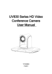
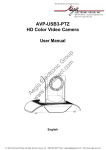
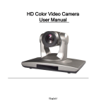
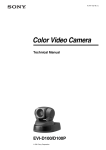
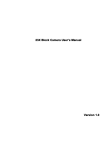
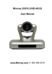
HuddleCamHD 18x
USB3.0
HD Color Video Camera
User Manual
English
Contact Sales (800) 486-5276
www.HuddleCamHD.com
Preface:
Thanks for using our HD color video conference camera.
This manual introduces the function installation and operation of the HD camera. Prior to
installation and usage, please read the manual thoroughly.
Warning
This product can be only used in specified range in order to avoid any damage or danger;
Don’t expose the camera to rain or moisture place
Don’t remove the cover to reduce the risk of electric shock. Refer servicing to qualified
personnel.
Never operate the camera under unqualified temperature , humidity and power supply;
Please use the soft cloth to clean the camera. Use neuter cleanser if bad smeared .Don’t use
the strong or cleanser avoiding scuffing.
Notes
Electromagnetic fields at the specific frequency may affect the image quality.
Quick Set up:
1) Plug camera power into camera and into wall outlet
a) Turn Camera on (If power switch is present) and wait for start-up
procedure to complete
2) Turn on Windows 7 PC
3) Once Windows 7 is fully booted up plug USB 3 cable into USB 3 port
4) The front of the camera has a red / blue LED that will flash in between
red and blue while the camera initializes after plugging the USB in
5) Once the camera has a solid blue LED on the front the camera it is
ready and in full operation mode
1
Contents
NOTES ..........................................................................................................................................................................................3
ACCESSORIES............................................................................................................................................................................3
FAST INSTALLATION ...............................................................................................................................................................3
CAMERA HIGHLIGHTS ...........................................................................................................................................................5
CAMERA SPECIFICATIONS....................................................................................................................................................5
CAMERA INTERFACE EXPLANATION................................................................................................................................6
REMOTE CONTROLLER EXPLANATION...........................................................................................................................7
USAGE OF IR REMOTE CONTROLLER ..............................................................................................................................8
RS-232C INTERFACE (PIN SPECS).......................................................................................................................................10
COM CONTROL....................................................................................................................................................................... 11
MENU SETTING........................................................................................................................................................................16
2
Notes
Electric Safety
Installation and operation must accord with electric safety standards.
Caution to transport
Avoid stress, vibration and soakage in transport, storage and installation.
Polarity of power supply
The power supply of the product is ±12V; the max electrical current is 2A.
Polarity of the power supply as the following drawing
Install Carefully
Never move the camera by seizing the camera head. Don’t rotate camera head by hand; otherwise,
mechanical trouble will occur.
This series item must put on the smooth desk or platform, and it can not be installed slantways;
If the camera is installed on TV or computer, the base can be fixed by three double-sided adhesive trays.
Don’t apply in corrosive liquid, gas or solid environment to avoid the cover which is made up of organic
material. To make sure no obstacle in rotation range
Never power on before installation is not completed
Don’t dispatch discretionarily
We are not responsible for any unauthorized modification or dismantling.
Accessories
When you open the box, check that all the supplied accessories are included:
Camera.....................................1
Power adapter .........................1
Power cable…………………….1
USB 3.0 data cable…………….1
RS232 cable…………………….1
Remote controller………………1
User manual ……………………1
Double-side glue shim ..............4
Fast Installation
1 The system platform is Win7 or Win8;
2 Interface of computer main board is equipped with a USB3.0
Recommended configuration cpu : core i3 3.4GHz; Display card Nvidia GT630;
Internal storage 6GB better to use desktop
3 Computer hardware device manager of universal serial bus (usb) controller are “USB3.0 Root Hub” and
“USB3.0Extensible host controller”
1. Please check the connection before turning on the power.
3
2. Dial switch setting at the bottom
Two DIP switch is set to ON; Namely select normal work mode.
SW2-2
1
2
3
4
ON
OFF
OFF
ON
SW2
-1
OFF
OFF
ON
ON
instruction
Undefined
Updating mode
Debugging mode
Working mode
3.rotary switch setting
The choice of 16 rotary switch video formats
Dial-up
0
1
2
3
4
5
6
7
1080P60
1080P50
1080P30
1080P25
720P60
720P50
720P30
720P25
8
--------
9
--------
A
--------
B
--------
C
--------
D
--------
E
--------
F
Display the video format set via OSD menu
Note: need to restart the camera after switching video format.
4.When the power supply switch is “on”, the indicator light is open (red color)
5. Confirm the computer device manager has the image device "Cyt-FX3" device, and then you can find the
"Cyt-FX3" device in the video client-side.
6. Confirm the computer installed USB3.0 driving. Computer hardware device manager of universal serial bus
(usb) controller are “USB3.0 Root Hub”and“USB3.0Extensible host controller” If not, please
install“Intel(R)_USB_3.0_extensible_Host_Controller_Driver
4
7.When testing the local video, software "e - CAMView” is available.
8.Test PC PTZ control with "AMCAP_PTZ" software to realize the dual function of video and control.Select
“Preview” in the menu “Options” and click “PTZ Control” window through menu “PTZ”. Source code control
protocol will be provided in the attachment.
9.When the camera is power-on and begin initialize, horizontally to the left turn to the limit position, vertically
turn to the bottom; finally both horizontal and vertical turn to the middle position. The motor stops running, and
initialization is completed. (Note: If the power-on mode is opened and saved preset position 0 or 1, then the
pan/tilt will be set to 0 or 1 preset position)
10. Factory Default : entry OSD menu by pressing the menu key of remote controller,
MENU ->
RESET -> ALL RESET , moving the left/right key to select Yes
then confirm by HOME key as
the following form,
RESET
SYS. RESET
CAM. RESET
P T. RESET
ALL. RESET
NO
NO
NO
NO
BACK
Camera Highlights
1.Chinese / English menu,convenient to use.
2. Provide high speed transmission USB3.0 interface, DVI-I interface(including the HDMI and YPbPr signal)
3. IR remote controller signal transparent transmission function: camera can receive both its own remote
controller signal and the one from terminal equipment, by transmitting the signal through VISCA IN to
terminal equipment IR receiver.
Camera Specifications:
5
1.
2.
3.
4.
5.
6.
7.
8.
9.
10.
11.
12.
13.
14.
15.
video format : 1080P60/50/30/25 720P60/50/30/25
Video Output Interface : USB3.0, DVI-I(including the HDMI and YPbPr signal)
Image Sensor : 1/2.8 inch 2 Megapixels high quality HD CMOS Sensor
Lens: f4.7mm-84.6mm, (18×optical zoom), F1.8-2.8, angle of view: 62°- 3.2°.
Rotation: ±170°for pan rotation, and -30°~+90°for tilt rotation, support up-side down installation.
Speed: 0.1°-180°/sec for pan rotation, 0.1°-80°/sec for tilt rotation.
Presets : 10 preset positions (can reach to128 presets by serial command), precision error less than 0.2°.
Support auto/ manual white balance/indoors/ out doors/ controller auto/ auto-track white balance ,
auto/manual exposure (iris , shuttle ) , auto/manual/One Push focus
support WDR function: with performance 100dB,
Control Signal interface : 8 pins mini DIN, RS232/RS485 VISCA/Pelco-D/Pelco-P protocol
Power interface : HEC3800 power jack , Power supply adapter: 12VDC/2A
Max power consumption: 12W
working temperature: -5 to +45
Storage temperature:-20 to +60
Weight: 1.3KG
Camera Interface Explanation
1.Camera lens
4.Remote Controller Receiver light
7.RS232 control interface
Dimension:
6
2.Camera base
5.Tripod screw hole
8. USB3.0 B Male interface
.
3.Power indicator light
6.Installation hole
9.12VDC Input Power Supply Jack
Remote Controller Explanation:
Definition of IR controller
0 Standby key
After pressing the standby key, the camera will step into standby
mode.Press again,the camera will open again.(Note: Standby
mode power consumption is about half of the normal mode)
1.Number key
Setting or locating presets
2.* key
Key combination use
3.Set preset key:
Set preset
Set preset key + 0-9 number key
Clear preset key
Clear preset key + 0-9 number key
or
+ +
clear all the presets
4.BLC control key
BLC ON open black light compensation only work when exposure
mode setting is Auto
BLC OFF close black light compensation Only available in the
exposure mode effective for Auto
5.Focus control key
Focus
focus length far from near
Focus
focus length near from far
Auto focus the camera focus mode is auto
Manual focus the camera focus mode is manual
6.Camera address selection
Select the camera which want to be controlled
7. # key
Key combination use
8.pan/tilt control key
Press key
up
Press key
down
Press
key
left
Press
key right
“HOME” key: Return to the middle position
9.Menu setting
Open or close the OSD menu
10.Zoom Control key
lens near
zoom
zoom
lens far
11.Camera IR remote control address selection
* +
+ F1
Camera Address No.1
* +
+ F2
Camera Address No. 2
* +
+ F3
Camera Address No. 3
* +
+ F4
Camera Address No. 4
7
Usage of IR Remote Controller
Finishing initialization, it can receive and execute the IR commands. Users can control the pan/tilt/zoom,
setting and running preset positions via the IR remote controller.
Key Instruction
1 In this instruction, “press the key” means a click rather than a long-press, and a special note will be given
if a long-press for more than one second is required.
2 When a key-combination is required, do it in sequence. For example, “
* + # + F1 ”means
press“ * ”first and then press“ # ” and press“ F1 ”at last.
1.Pan/Tilt Control
Up:
press
Down: press
Left:
press
Right:
press
Back to middle position press HOME
Press and hold the up/down/left/right key, the pan/tilt will keep running, from slow to fast, until it run to the
endpoint; The pan/tilt running stops as soon as the key is released.
2. Zoom Control
key
ZOOM OUT: press ZOOM
ZOOM IN: press ZOOM
key
Press and hold the key, the camera will keep zooming in or zooming out and stops as soon as the key is
released.
Support Auto and Manual focus
3. Focus Control
Focus (far) Press
focus+ key
Focus (near)
Press
focus- key
8
Auto Focus: Press auto
Manual Focus: Press manual
Press and hold the key, the action of focus continues and stops as soon as the key is released.
4.BLC Setting
BLC ON / OFF :not support
5. Presets setting
1 Preset setting : to set a preset position, the users should press the
SET PRESET key first and then
press the number key 0-9 to set a relative position, 10 preset positions in total are available.
2 Preset clearing : to clear a preset position, the user can press the CLEAR PRESET key first and then
press the number key 0-9 to clear the relative position;
Note : press the # key three times continually to cancel all the presets.
6
Preset Running
Press a number key 0-9 directly to run a relative preset.
Note: Action in vain if a relative preset position does not exist.
7
Camera Selection
Select the camera number to control.
8
Camera Remote Controller Address Setting
*
*
*
*
+
+
+
+
+
+
+
+
F1
F2
F3
F4
Camera Address No.1
Camera Address No. 2
Camera Address No. 3
Camera Address No. 4
9
RS-232C Interface (Pin Specs)
Camera
1.DTR
2.DSR
3.TXD1
4.GND
5.RXD1
6.RS485-A
7.IR OUT
8.RS485-B
Camera
No.
Function
1
DTR
2
DSR
3
TXD 1
4
GND
5
RXD 1
6
RS485-A
7
IR OUT
8
RS485-B
Camera
1.DTR
2.DSR
3.TXD1
4.GND
5.RXD1
6.RS485-A
7.IR OUT
8.RS485-B
9.GND
10
RS485
A
B
1.DTR
2.DSR
3.TXD
4.GND
5.RXD
6.RS485-A
7.IR OUT
8.RS485-B
Windows DB-9
1.CD
2.RXD
3.TXD
4.DTR
5.GND
6.DSR
7.RTS
8.CTS
9.RI
Mini DIN
1.DTR
2.DSR
3.TXD
4.GND
5.RXD
6.GND
7.NC
8.NC
COM Control
In normal working mode, the camera is able to be controlled via RS-232C/RS485 command (VISCA IN) .
The parameter of the RS232C/RS485 COM is as following :
Baud Rate
2400/4800/9600/115200 bit/s
Start bit 1bit ;
Data bit: 8bit ;
Stop bit : 1bit;
Code:
None
Connected to power, the camera runs to the down left, then back to middle, with the farthest zoom rate in the
auto focus and auto iris mode. After initialization,the camera runs to the preset No.0 or 1 if it is saved.Then
the users can control the camera via serial command.
VISCA Protocol
Part1 . Camera Return Command
Ack/Completion Message
Command Packet
z0 41 FF
z0 51 FF
ACK
Completion
z = Camera Address + 8
Note
Returned when the command is accepted.
Returned when the command has been executed.
Error Messages
Command Packet
Note
Syntax Error
z0 60 02 FF
Returned when the command format is different or when a
command with illegal command parameters is accepted
Command Not Executable
z0 61 41 FF
Returned when a command cannot be executed due to current
conditions. For example, when commands controlling the focus
manually are received during auto focus.
Part 2
Camera Control Command
Command
Function
Commad Packet
Note
AddressSet
Broadcast
88 30 01 FF
Address setting
IF_Clear
Broadcast
88 01 00 01 FF
I/F Clear
On
8x 01 04 00 02 FF
Off
8x 01 04 00 03 FF
Stop
8x 01 04 07 00 FF
Tele(Standard)
8x 01 04 07 02 FF
Wide(Standard)
8x 01 04 07 03 FF
Tele(Variable)
8x 01 04 07 2p FF
Wide(Variable)
8x 01 04 07 3p FF
Direct
8x 01 04 47 0p 0q 0r 0s FF
CommandCancel
CAM_Power
CAM_Zoom
CAM_Focus
CAM_ZoomFocus
CAM_WB
8x 21 FF
Stop
8x 01 04 08 00 FF
Far(Standard)
8x 01 04 08 02 FF
Near(Standard)
8x 01 04 08 03 FF
Power ON/OFF
p = 0(low) - 7(high)
pqrs: Zoom Position
Direct
8x 01 04 48 0p 0q 0r 0s FF
pqrs: Focus Position
One Push AF
Auto
8x 01 04 18 01 FF
8x 01 04 47 0p 0q 0r 0s
0t 0u 0v 0w FF
8x 01 04 35 00 FF
pqrs: Zoom Position
tuvw: Focus Position
Normal Auto
Indoor
8x 01 04 35 01 FF
Outdoor
8x 01 04 35 02 FF
OnePush
8x 01 04 35 03 FF
Manual
8x 01 04 35 05 FF
Direct
11
Command
CAM_RGain
CAM_Bgain
CAM_AE
CAM_Shutter
CAM_Iris
CAM_Gain
CAM_Bright
CAM_ExpComp
CAM_Aperture
CAM_Memory
CAM_LR_Reverse
CAM_PictureFlip
Function
Commad Packet
Reset
8x 01 04 03 00 FF
Up
8x 01 04 03 02 FF
Down
8x 01 04 03 03 FF
Direct
8x 01 04 43 00 00 0p 0q FF
Reset
8x 01 04 04 00 FF
Up
8x 01 04 04 02 FF
Down
8x 01 04 04 03 FF
Direct
8x 01 04 44 00 00 0p 0q FF
Note
Manual Control of R Gain
pq: R Gain
Manual Control of B Gain
pq: B Gain
Full Auto
8x 01 04 39 00 FF
Automatic Exposure mode
Manual
8x 01 04 39 03 FF
Manual Control mode
Shutter priority
8x 01 04 39 0A FF
Shutter Priority Automatic Exposure mode
Iris priority
8x 01 04 39 0B FF
Iris Priority Automatic Exposure mode
Bright
8x 01 04 39 0D FF
Bright mode(Manual control)
Reset
8x 01 04 0A 00 FF
Up
8x 01 04 0A 02 FF
Down
8x 01 04 0A 03 FF
Direct
8x 01 04 4A 00 00 0p 0q FF
Reset
8x 01 04 0B 00 FF
Up
8x 01 04 0B 02 FF
Down
8x 01 04 0B 03 FF
Direct
8x 01 04 4B 00 00 0p 0q FF
Reset
8x 01 04 0C 00 FF
Up
8x 01 04 0C 02 FF
Shutter Setting
pq: Shutter Position
Iris Setting
pq: Iris Position
Gain
Setting
Down
8x 01 04 0C 03 FF
Direct
8x 01 04 0C 00 00 0p 0q FF
pq: Gain Positon
Direct
8x 01 04 4D 00 00 0p 0q FF
pq: Bright l Positon
On
8x 01 04 3E 02 FF
Off
8x 01 04 3E 03 FF
Reset
8x 01 04 0E 00 FF
Up
8x 01 04 0E 02 FF
Down
8x 01 04 0E 03 FF
Direct
8x 01 04 4E 00 00 0p 0q FF
Reset
8x 01 04 02 00 FF
Up
8x 01 04 02 02 FF
Exposure Compensation ON/OFF
Exposure Compensation Amount Setting
pq: ExpComp Position
Aperture Control
Down
8x 01 04 02 03 FF
Direct
8x 01 04 42 00 00 0p 0q FF
pq: Aperture Gain
Reset
8x 01 04 3F 00 0p FF
Set
8x 01 04 3F 01 0p FF
Recall
8x 01 04 3F 02 0p FF
p: Memory Number(=0 to 127)
Corresponds to 0 to 9 on the Remote
Commander
On
8x 01 04 61 02 FF
Off
8x 01 04 61 03 FF
On
8x 01 04 66 02 FF
Off
8x 01 04 66 03 FF
Image Flip Horizontal ON/OFF
Image Flip Vertical ON/OFF
VideoSystem Set
8x 01 06 35 00 0p FF
CAM_IDWrite
8x 01 04 22 0p 0q 0r 0s FF
P: Video format
1:1080P60
2:1080P50
4:720P60
5:720P50
6:1080P30
7:1080P25
8:720P30
9:720P25
pqrs: Camera ID (=0000 to FFFF)
8x 01 06 06 03 FF
Turn off the menu
SYS_Menu
12
OFF
Command
IR_Receive
IR_ReceiveReturn
Pan_tiltDrive
Function
Commad Packet
On
8x 01 06 08 02 FF
Off
8x 01 06 08 03 FF
On/Off
8x 01 06 08 10 FF
On
8x 01 7D 01 03 00 00 FF
Off
8x 01 7D 01 13 00 00 FF
Up
8x 01 06 01 VV WW 03 01 FF
Down
8x 01 06 01 VV WW 03 02 FF
Left
8x 01 06 01 VV WW 01 03 FF
Right
8x 01 06 01 VV WW 02 03 FF
Upleft
8x 01 06 01 VV WW 01 01 FF
Upright
8x 01 06 01 VV WW 02 01 FF
DownLeft
8x 01 06 01 VV WW 01 02 FF
DownRight
8x 01 06 01 VV WW 02 02 FF
Stop
8x 01 06 01 VV WW 03 03 FF
8x 01 06 02 VV WW
0Y 0Y 0Y 0Y 0Z 0Z 0Z 0Z FF
8x 01 06 03 VV WW
0Y 0Y 0Y 0Y 0Z 0Z 0Z 0Z FF
8x 01 06 04 FF
AbsolutePosition
RelativePosition
Home
Reset
Set
Pan-tiltLimitSet
Clear
8x 01 06 05 FF
8x 01 06 07 00 0W
0Y 0Y 0Y 0Y 0Z 0Z 0Z 0Z FF
8x 01 06 07 01 0W
07 0F 0F 0F 07 0F 0F 0F FF
Note
IR(remote commander)receive ON/OFF
IR(remote commander)receive message via
the VISCA communication ON/OFF
VV: Pan speed 0x01 (low speed) to 0x18 (high
speed)
WW: Tilt speed 0x01 (low speed) to 0x14 (high
speed)
YYYY: Pan Position(TBD)
ZZZZ: Tilt Position(TBD)
W:1 UpRight 0:DownLeft
YYYY: Pan Limit Position(TBD)
ZZZZ: Tilt Limit Position(TBD)
Part3 Inquiry Command
Command
Command Packet
CAM_PowerInq
8x 09 04 00 FF
CAM_ZoomPosInq
8x 09 04 47 FF
CAM_FocusModeInq
8x 09 04 38 FF
CAM_FocusPosInq
8x 09 04 48 FF
CAM_WBModeInq
8x 09 04 35 FF
CAM_RGainInq
CAM_BGainInq
8x 09 04 43 FF
8x 09 04 44 FF
CAM_AEModeInq
8x 09 04 39 FF
CAM_ShutterPosInq
CAM_IrisPosInq
CAM_GainPosiInq
CAM_ BrightPosiInq
CAM_ExpCompModeInq
8x 09 04 4A FF
8x 09 04 4B FF
8x 09 04 4C FF
8x 09 04 4D FF
8x 09 04 3E FF
CAM_ExpCompPosInq
CAM_ApertureInq
CAM_MemoryInq
SYS_MenuModeInq
8x 09 04 4E FF
8x 09 04 42 FF
8x 09 04 3F FF
8x 09 06 06 FF
CAM_LR_ReverseInq
8x 09 04 61 FF
CAM_PictureFlipInq
8x 09 04 66 FF
CAM_IDInq
CAM_VersionInq
8x 09 04 22 FF
8x 09 00 02 FF
Return Packet
y0 50 02 FF
y0 50 03 FF
y0 50 0p 0q 0r 0s FF
y0 50 02 FF
y0 50 03 FF
y0 50 0p 0q 0r 0s FF
y0 50 00 FF
y0 50 01 FF
y0 50 02 FF
y0 50 03 FF
y0 50 04 FF
y0 50 05 FF
y0 50 00 00 0p 0q FF
y0 50 00 00 0p 0q FF
y0 50 00 FF
y0 50 03 FF
y0 50 0A FF
y0 50 0B FF
y0 50 0D FF
y0 50 00 00 0p 0q FF
y0 50 00 00 0p 0q FF
y0 50 00 00 0p 0q FF
y0 50 00 00 0p 0q FF
y0 50 02 FF
y0 50 03 FF
y0 50 00 00 0p 0q FF
y0 50 00 00 0p 0q FF
y0 50pp FF
y0 50 02 FF
y0 50 03 FF
y0 50 02 FF
y0 50 03 FF
y0 50 02 FF
y0 50 03 FF
y0 50 0p 0q 0r 0s FF
y0 50 ab cd
Note
On
Off(Standby)
pqrs: Zoom Position
Auto Focus
Manual Focus
pqrs: Focus Position
Auto
Indoor mode
Outdoor mode
OnePush mode
ATW
Manual
pq: R Gain
pq: B Gain
Full Auto
Manual
Shutter priority
Iris priority
Bright
pq: Shutter Position
pq: Iris Position
pq: Gain Position
pq: Bright Position
On
Off
pq: ExpComp Position
pq: Aperture Gain
pp: Memory number last operated.
On
Off
On
Off
On
Off
pqrs: Camera ID
13
Command
Command Packet
VideoSystemInq
8x 09 06 23 FF
IR_Receive
8x 09 06 08 FF
Return Packet
mn pq rs tu vw FF
P: 4~9 Video format
4:720P60
5:720P50
6:1080P30
7:1080P25
8:720P30
9:720P25
y0 50 0p FF
y0 50 02 FF
y0 50 03 FF
y0 07 7D 01 04 00 FF
y0 07 7D 01 04 07 FF
y0 07 7D 01 04 38 FF
y0 07 7D 01 04 33 FF
y0 07 7D 01 04 3F FF
y0 07 7D 01 06 01 FF
IR_ReceiveReturn
Pan-tiltMaxSpeedInq
8x 09 06 11 FF
y0 50 ww zz FF
Pan-tiltPosInq
8x 09 06 12 FF
y0 50 0w 0w 0w 0w
0z 0z 0z 0z FF
Note :
x
Note
means the camera address you want to control ,
On
Off
Power ON/OFF
Zoom tele/wide
AF On/Off
CAM_Backlight
CAM_Memory
Pan_tiltDrive
ww: Pan Max Speed
zz: Tilt Max Speed
wwww: Pan Position
zzzz: Tilt Position
y = x+8
Pelco-D Protocol Command List
Function
Byte1
Byte2
Byte3
Byte4
Byte5
Byte6
Byte7
Up
0xFF
Address
0x00
0x08
Pan Speed
Tilt Speed
SUM
Down
0xFF
Address
0x00
0x10
Pan Speed
Tilt Speed
SUM
Left
0xFF
Address
0x00
0x04
Pan Speed
Tilt Speed
SUM
Right
0xFF
Address
0x00
0x02
Pan Speed
Tilt Speed
SUM
Upleft
0xFF
Address
0x00
0x0C
Pan Speed
Tilt Speed
SUM
Upright
0xFF
Address
0x00
0x0A
Pan Speed
Tilt Speed
SUM
DownLeft
0xFF
Address
0x00
0x14
Pan Speed
Tilt Speed
SUM
Upleft
0xFF
Address
0x00
0x0C
Pan Speed
Tilt Speed
SUM
Zoom In
0xFF
Address
0x00
0x20
0x00
0x00
SUM
Zoom Out
0xFF
Address
0x00
0x40
0x00
0x00
SUM
Focus Far
0xFF
Address
0x00
0x80
0x00
0x00
SUM
Focus Near
0xFF
Address
0x01
0x00
0x00
0x00
SUM
Set Preset
0xFF
Address
0x00
0x03
0x00
Preset ID
SUM
Clear Preset
0xFF
Address
0x00
0x05
0x00
Preset ID
SUM
Call Preset
0xFF
Address
0x00
0x07
0x00
Preset ID
SUM
Query Pan Position
0xFF
Address
0x00
0x51
0xFF
Address
0x00
0x59
Query Tilt Position
0xFF
Address
0x00
0x53
Query Tilt Position Response
0xFF
Address
0x00
0x5B
Query Zoom Position
Query Zoom Position
Response
0xFF
Address
0x00
0x55
0xFF
Address
0x00
0x5D
0x00
Value Low
Byte
0x00
Value Low
Byte
0x00
Value Low
Byte
SUM
Query Pan Position Response
0x00
Value High
Byte
0x00
Value High
Byte
0x00
Value High
Byte
SUM
SUM
SUM
SUM
SUM
Pelco-P Protocol Command List
Byte3
Byte4
Byte7
Byte8
Up
Function
0xA0
Address
0x00
0x08
Pan Speed
Tilt Speed
0xAF
XOR
Down
0xA0
Address
0x00
0x10
Pan Speed
Tilt Speed
0xAF
XOR
Left
0xA0
Address
0x00
0x04
Pan Speed
Tilt Speed
0xAF
XOR
Right
0xA0
Address
0x00
0x02
Pan Speed
Tilt Speed
0xAF
XOR
Upleft
0xA0
Address
0x00
0x0C
Pan Speed
Tilt Speed
0xAF
XOR
Upright
0xA0
Address
0x00
0x0A
Pan Speed
Tilt Speed
0xAF
XOR
14
Byte1
Byte2
Byte5
Byte6
Function
Byte1
Byte2
Byte3
Byte4
Byte5
Byte6
Byte7
Byte8
DownLeft
0xA0
Address
0x00
0x14
Pan Speed
Tilt Speed
0xAF
XOR
DownRight
0xA0
Address
0x00
0x12
Pan Speed
Tilt Speed
0xAF
XOR
Zoom In
0xA0
Address
0x00
0x20
0x00
0x00
0xAF
XOR
Zoom Out
0xA0
Address
0x00
0x40
0x00
0x00
0xAF
XOR
Focus Far
0xA0
Address
0x00
0x80
0x00
0x00
0xAF
XOR
Focus Near
0xA0
Address
0x01
0x00
0x00
0x00
0xAF
XOR
Set Preset
0xA0
Address
0x00
0x03
0x00
Preset ID
0xAF
XOR
Clear Preset
0xA0
Address
0x00
0x05
0x00
Preset ID
0xAF
XOR
Call Preset
0xA0
Address
0x00
0x07
0x00
Preset ID
0xAF
XOR
Query Pan Position
Query Pan Position
Response
Query Tilt Position
0xA0
Address
0x00
0x51
XOR
Address
0x00
0x59
0xAF
XOR
0xA0
Address
0x00
0x53
0xAF
XOR
Query Tilt Position Response
0xA0
Address
0x00
0x5B
0xAF
XOR
Query Zoom Position
Query Zoom Position
Response
0xA0
Address
0x00
0x55
0xAF
XOR
0xA0
Address
0x00
0x5D
0x00
Value Low
Byte
0x00
Value Low
Byte
0x00
Value Low
Byte
0xAF
0xA0
0x00
Value High
Byte
0x00
Value High
Byte
0x00
Value High
Byte
0xAF
XOR
15
Menu Setting
1. Main Menu
In normal working mode, press
the selected items.
MENU key to display the menu, using scroll arrow to point at or highlight
MAIN
LANGUAGE
SYSTEM OPTION
CAMERA OPTION
PT OPTION
V. FORMAT
RESET
HELP
EXIT
LANGUAGE: Language setting, Chinese / English
SYSTEM OPTION system setting
CAMERA OPTION camera setting
PT OPTION pan tilt setting
V. FORMAT: video format setting
RESET reset setting
HELP for help
2. SYSTEM OPTION
Move the pointer to the (SYSTEM SET) in the Main Menu, click the HOME and enter the (SYSTEM SET) as
follow,
SYSTEM SET
PROTOCOL
ADDR
B. RATE
RS485
ARM. VER
. VER
CAM. VER
MODEL
VISCA
01
9600
OFF
1.0A
1.0
010404
UH-S
BACK
PROTOCOL: Reset Condition VISCA
Protocol type:VISCA/Pelco-P/Pelco-D
ADDR Reset Condition: 01
VISCA=1~7
Pelco-P/Pelco-D = 1~63
B. RATE Reset Condition:9600
2400/4800/9600/115200
RS485 Reset Condition:off
It is ON when using RS485 communication
VER./
VER/CAM VER: version information,it will upgrate synchronously with the
software
Machine Model: Machine internal identified code UH-S
3. CAMERA OPTION
Move the pointer to the (CAMERA SET) in the Main Menu, click the HOME and enter the (CAMERA SET) as
follow,
16
CAMERA SET
EXPOSURE
COLOR
LEN
BACK
EXPOSURE exposure setting
COLOR: color setting
LEN: lens setting
3.1 EXPOSURE SETTING
Move the pointer to the (EXPOSURE) in the Main Menu, click the HOME and enter the (EXPOSURE SET) as
follow,
EXPOSURE SET
EXP. MODE
SHUTTER
IRIS
GAIN
BRIGHT
EV. MODE
LEVEL
WDR
LEVEL
Auto
---5
off
-off
--
BACK
EXP. MODE Reset Condition: Auto
Available mode: Auto Manual Shutter Iris
SHUTTER Reset Condition: Default
Available selections: 1/60 1/90 1/100 1/125 1/180 1/250 1/350 1/500 1/725 1/1000
1/1500 1/2000 1/3000 1/4000 1/6000 1/10000 only available in Manual Shutter mode
IRIS Reset Condition: Default
Available:0~13 only available in Manual Iris mode
BRIGHT Reset Condition: 5
Available: 0~9
GAIN: Reset Condition: Default
Available: 0~15 only available in Manual mode
EV MODE
Reset Condition: off
Available: On/Off (only available in non manual model)
LEVEL: Reset Condition: Default
Available Setting: -3~3
WDR : Reset Condition: off
Available: On/Off
LEVEL Reset Condition: Default
Available Setting: 0~5
3.2 COLOR SETTING
Move the pointer to the (COLOR SET) in the Main Menu, click the
follow,
HOME
and enter the (COLOR SET) as
17
COLOR
WB.MODE
R.GAIN
B.GAIN
GAMMA
SATURATION
APERTURE
FLICK
NR LEVEL
CONTRAST
BACK
ATW
--0
3
5
Off
2
3
WB MODE Reset Condition: ATW
White balance mode setting: Auto Indoor Outdoor OnePush
R.GAIN Reset Condition:Default
Red gain setting 0~50 only available in Manual mode
B.GAIN Reset Condition:Default
Blue gain setting 0~50 only available in Manual mode
GAMMA: Reset Condition:0
GAMMA setting: 0~3
SATURATION: Reset Condition:3
SATURATION setting: 0~9
APERTURE Reset Condition:5
APERTURE setting: 0~9
FLICK Reset Condition:off
FLICK setteing50HZ/60HZ/OFF
NR LEVEL: Reset Condition:2
NR LEVEL setting: 0~9
CONTRAST: Reset Condition:3
CONTRAST setting:0~9
ATW Manual
3.3 LENS SETTING
Move the pointer to the (LEN SET) in the Main Menu, click the HOME
and enter the (LEN SET) as follow,
LEN
FOCUS
AUTO
BACK
FOCUS
Auto Manual
OnePush
4. PAN TILT SETTING
Move the pointer to the (PT SET) in the Main Menu, click the HOME
and enter the (PT SET) as follow,
PT SET
POWER. ACT
SPEEDBYZ
MOUNT. MODE
IR M.SPEED
IR Z.SPEED
MIN.SPEED
SCAN. SPEED
Off
On
Up
16
07
0
10
BACK
POWER ACT
Reset Condition: OFF
0/1( the camera will move to no.0/1 preset position after 12 seconds without control since
power on), Off
SPEEDBYZ Reset Condition: On
only work for IR remote control:
On when the camera zoom becomes larger, rotation speed comes down , Off
18
MOUNT.MODE
Reset Condition: Up
UP, DOWN
IR M.SPEED Reset Condition: 16
IR remote control move speed: 5~24
IR Z.SPEED Reset Condition: 07
IR remote control zoom speed: 1~7
MIN.SPEED: Reset Condition: 0
Minimum start speed for serial command: 0~9
SCAN. SPEED: Reset Condition: 10
move speed: 4~15
5. RESET
Move the pointer to the (SET) in the Main Menu, click the HOME
and enter the (SET) as follow,
RESET
SYSTEM. RESET
CAM.RESET
PT. RESET
ALL. RESET
NO
NO
NO
NO
BACK
SYS. RESET system reset:Protocol: VISCA; Address: 1; baud rate:9600; S485:Off
CAM. RESET camera parameter reset
PT. RESET power action: Off; speed by zone: On; mount mode:Up;
IR move speed:16; IR zoom speed: 7;MIN.SPEED 0;SCAN. SPEED 10
ALL RESET
reset above 3 items
6. HELP
Show instruction of the OSD menu operation
HELP
SELET MENU
CHANGESETTING
ENTER
RETURN
BACK
7. EXIT
In main menu, press the key MENU
again will show the exit window as follows:
EXIT
SAVE
Yes/No
OK
BACK
SAVE
to save settings Yes No.
Notice press HOME key to confirm;
press MENU key to return to the main menu
19
Troubleshooting
Camera Maintains
If camera is not used for long time, please turn off power adapter switch and AC plug.
Use soft cloth or tissue to clean the camera cover.
Use soft cloth to clean the lens; Use neuter cleanser if bad smeared. No use strong or corrosive cleanser or
corrosive cleanser avoiding scuffing.
Unqualified Application
No shooting extreme light object, such as sunlight, lamplight etc.
No operating in unstable light environment, otherwise image will twinkle
No operating in radio wave with great power environment, such as TV station or Wireless Launcher etc.
Image effective will not be good when the light is not accordant with camera’s lux.
Troubleshooting
Image
No image
1, Check whether the power cord, voltage is OK, power indicator light is ON.
2, Turn off the power supply to check whether the camera can auto configure.
3, Check the dial switch in bottom and make sure the two dial position are all on OFF.
4, Check video and TV wire is connected correctly.
Abnormal display of image
Check whether the video connecting wires is well and other connecting sockets and camera
flat wires are well.
The camera can only works at one focus, other position can not be focused.
Change the position to see if this phenomenon still exists. If yes, it may be caused by
Camera control drive focus control system trouble.
Image dithering when at Maximum Zoom
1, Check whether camera is fixed correctly.
2, If there is vibrative mechanical object.
Remote Controller
1, Change the battery
2, Check the camera operation mode is right.
Terminal
1, Check the camera operation mode is right.
2, Check control wire is connected correctly.
Contact Sales (800) 486-5276
www.HuddleCamHD.com
20