1
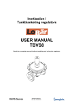
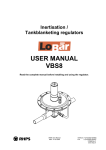
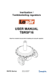
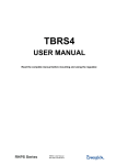
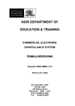
RHPS Series
BD(H) 20, 25 (-DP)
User Manual
Read the complete manual before installing and using the regulator.
WARNING
Before removing a regulator from the system for service, you must
▪ depressurize system
▪ purge the system to remove any residual system media left in the regulator.
Contents
Introduction ............................................................................................................................................ 3
Installation .............................................................................................................................................. 5
Operation ................................................................................................................................................ 8
Maintenance ............................................................................................................................................ 9
Testing .................................................................................................................................................. 10
Troubleshooting ................................................................................................................................... 11
2
Introduction
Representative drawing of the standard BD20, 25-DP
1
2
3
4
5
6
7
8
9
10
body assembly
dome
bodyplug
valve case
valve screw
pistonplate
piston
seat
11
12
13
14
16
17
21
22
25
26
guide ring
o-ring
setspring
o-ring
valve insert
o-ring
o-ring
o-ring
retaining ring
27
28
29
30
31
springguide
domescrew
ring
socket head cap screw
setscrew
3
Dome loading with differential pressure
A differential pressure dome loaded regulator has a set spring inside the dome.
The set spring is used to maintain a desired pressure difference between the dome pressure and the
outlet pressure.
Usually the dome pressure is a reference pressure taken elsewhere out of the system.
2
13
14
15
20
21
24
25
26
27
28
30
31
dome
diaphragm plate
diaphragm
bottom springguide
o-ring
o-ring
socket head cap screw
ring
retaining ring
set spring
springguide
dome screw
setscrew
4
Installation
WARNING
When installing a Swagelok® self-venting regulator, position the vent connection or
line away from operating personnel. Operating personnel must protect themselves
from exposure to system fluids.
CAUTION
Do not use the regulator as a shutoff device.
CAUTION
When using the BDH20 or BDHF25 with an inlet pressure higher than 200 bar (2 902
psig), a safety valve must be installed in the outlet line, because the outlet pressure
may not exceed 200 bar (2 902 psig).
Connections to System
The preferred mounting position of the regulator is horizontal with the dome facing upwards.
If grounding is required, connect a ground wire under a dome bolt.
5
Filling the dome
The dome can be filled in different ways.
1.
2.
This can be done by taking the gas or liquid pressure from the system and feeding this through
a needle valve or fixed orifice into the dome.
A spring loaded back pressure regulator controls the dome pressure. The outlet pressure from
the pilot regulator could be vented to the atmosphere or into the outlet line.
This is shown in sketch A.
The pressure in the dome can also be controlled with an external pressure source. The gas
pressure can be taken from a cylinder or shop air mains.
A spring loaded pressure regulator controls the dome pressure. The regulator works best with a
continuous bleed on the dome.
This is shown in sketch B.
CAUTION
It is not recommended to place a gauge on the dome to check the set pressure.
Because of forces in the regulator, the dome pressure will always be lower than the
inlet pressure. Place a gauge in the inlet line to check the set pressure.
sketch A
sketch B
External feedback
CAUTION
When using the regulator with external feedback, option –EF, make sure that the outlet
pressure can be fed back to the external feedback connection before applying
pressure to the regulator. Failing to do so may lead to damage and non-functioning of
the regulator as the inlet pressure will be put straight through to the outlet.
The purpose of the external feedback on a pressure regulator is to get a more accurate regulation of
the outlet pressure. This can be achieved by sensing the outlet pressure downstream of the regulator
and feeding it back to the regulator. For this purpose Swagelok has provided a special connection,
marked on the regulator itself as "external feedback".
6
Connecting the external feedback
The external feedback must be installed as follows:
▪ The external feedback is to be connected in a turbulence-free zone in the downstream piping,
at a maximum distance of 5x the outside diameter of the down stream piping.
▪ The external feedback must be connected on top of the downstream piping.
CAUTION
Never connect the external feedback line downstream of a shut-off valve.
Principle sketch of external feedback:
7
Operation
Note: All directions are when viewed from above.
▪ Inlet and set pressure settings are obtained by adjusting pressure in the dome.
▪ Increase the pressure in the dome to increase the inlet pressure.
▪ Decrease the pressure in the dome to decrease the inlet pressure.
▪ Icing of the regulator at high flow rates or high pressure drops may occur if the gaseous media or
atmosphere contains moisture.
▪ An auxiliary upstream filter is recommended for use in all but the cleanest of media.
▪ If the shut-off valve at the outlet side is closed after changing the set pressure, the outlet pressure
will rise a little because of the closing force required for bubble-tight closing of the regulator.
▪ This phenomenon is usually referred to as the “lock-up” and does not indicate a problem with
the regulator.
▪ After flow, the inlet pressure will fall a little under the set pressure.
This is because of the closing force required for bubble-tight closing of the regulator.
▪ This phenomenon is usually referred to as the “reseat pressure” and does not indicate a
problem with the regulator.
▪ An increase in the flow will result in a rise of the set pressure.
A decrease in the flow will result in a fall of the set pressure.
This is because of the force required for opening the valve of the regulator.
▪ This phenomenon is usually referred to as the “accumulation pressure” and does not
indicate a problem with the regulator.
▪ An increase of the outlet pressure will result in a fall of the set pressure.
A decrease of the outlet pressure will result in a rise of the set pressure.
▪ This phenomenon is usually referred to as the “dependency” and does not indicate a
problem with the regulator.
8
Maintenance
Required tools for maintenance
▪
▪
▪
▪
▪
▪
▪
▪
▪
a vice to fasten the regulator
pincers to take out the o-rings
a torque wrench
a torque wrench hexagon head key 10 mm
a torque wrench “open-end insert tool”, 38 mm (-DP only) & 46 mm
an open-end wrench, 15 mm (-DP only)
media and temperature compatible lubricant for reassembling threaded parts
media and temperature compatible lubricant for o-rings
Snoop® liquid leak detector
Disassembly
▪
▪
Loosen the hexagon socket head screws and remove the dome, dome plate, piston(plate) and
valve assembly.
Loosen the body plug and remove the seat.
Inspection of disassembled parts
▪
Check all parts for abnormal wear. Replace parts in case of doubt.
Points of attention before assembly
▪
▪
▪
▪
All parts must be clean and undamaged before starting assembly.
Swagelok recommends replacing all o-rings and the diaphragm before assembly.
All threaded parts must be lightly lubricated before assembly to avoid galling of threads.
All o-rings need to be lightly lubricated to improve the lifetime of the o-ring and the performance of
the regulator.
Assembly
Follow the points for disassembly in reverse order to assemble the regulator.
Recommended torques
CAUTION
Only tighten the bolts or parts if the regulator is completely depressurized.
▪
▪
▪
Hexagon socket head screws M12
Bodyplug
Dome screw (-DP only)
50 N·m (442 in.·lb)
50 N·m (442 in.·lb)
30 N·m (265 in.·lb)
9
Testing
Check the regulator for leakage across the seat, with low- and high inlet pressure.
Check the regulator for leakage across the diaphragm, with low- and high outlet pressure.
A well performing BD(H)20/BD(H)F25 is 100 % bubble tight.
If there is a leakage across the seat or the diaphragm, the damaged parts must be replaced.
10
Troubleshooting
Problem:
The outlet pressure creeps up, without increasing the dome pressure.
Cause:
A damaged valve and/or seat.
Solution:
Replace the valve and/or the seat.
Problem:
Leakage around the bodyplug.
Cause:
A damaged o-ring or insufficient torque on the body plug.
Solution:
Replace the o-ring or tighten the bodyplug according to the torque specifications.
Problem:
Leakage between the body and the dome.
Cause:
A damaged diaphragm or insufficient torque on the bolts.
Solution:
Replace the diaphragm or tighten the bolts according to the torque specifications.
Problem:
The required set pressure can not be reached.
Cause:
The inlet pressure is not high enough.
Solution:
Make sure that the inlet pressure is sufficient.
Problem:
The inlet pressure rises too much when going from a dynamic to a static situation.
Cause:
There is too much flow in the dynamic situation.
Solution:
A larger regulator is required.
Check the specific application data with the flow curves in our product literature, if available.
Problem:
The outlet pressure does not drop if the pressure in the dome is lowered.
Cause:
The valve is sticking.
Solution:
Replace the valve assembly.
Problem:
The outlet pressure has changed without adjusting the dome pressure.
Cause:
Changes to the inlet pressure will result in changes to the outlet pressure.
Solution:
Maintain a constant inlet pressure to the regulator. See section “operation” about dependency.
Problem:
The regulator will not relieve at the set point.
Cause:
The valve assembly is sticking or the dome pressure is accidentally adjusted.
Solution:
Replace the valve assembly or re-adjust the dome pressure.
11
Warranty Information
Swagelok products are backed by The Swagelok Limited Lifetime Warranty.
For a copy, visit swagelok.com or contact your authorized Swagelok representative.
For additional information, see www.swagelok.com.
Caution: Do not mix or interchange parts
with those of other manufacturers.
Swagelok, Snoop – Swagelok Company
© 2010 Swagelok Company
December 2010, R0
MS-CRD-0151